E
WARNINGS, CAUTIONS AND NOTES
Attention is drawn to the various Warnings, Cautions and Notes which distinguish important
information in this manual in the following ways.
The Safety Alert Symbol means ATTENTION! BECOME ALERT! YOUR SAFETY IS
INVOLVED!
WARNING
Failure to follow WARNING instructions could result in severe injury or death to the machine
operator, a bystander, or a person inspecting or repairing the outboard motor.
CAUTION:
A CAUTION indicates special precautions that must be taken to avoid damage to the out-
board motor.
NOTE:
A NOTE provides key information to make procedures easier or clearer.
SPECIFICATIONS
These are given in bold type at each procedure. It is not necessary to leave the section deal-
ing with the procedure in order to look up the specifications.
It is important to note the differences in specifications of models. When a procedure relates to
more than one model, the main differences in specifications will be shown in a following table.
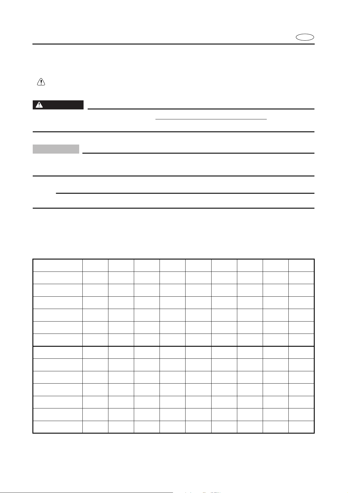
Model name 40VMH 40VMHD 40VMHO 40VMO 40VWH 40VE 40VEO 40VEHTO 40VET
Starting system Manual Manual Manual Manual Manual
& Electric Electric Electric Electric Electric
Control system Tiller Tiller Tiller Remote Tiller Remote Remote Tiller Remote
Trim/Tilt system Manual tilt Hydro tilt Manual tilt Manual tilt Hydro tilt Manual tilt Manual tilt PTT PTT
Lubrication system Pre-Mixed
Pre-Mixed Oil injection Oil injection Pre-Mixed
Pre-Mixed
Oil injection Oil injection
Pre-Mixed
Warning indicator
lamp 1111113——
Enrichment system Choke Choke Choke Choke
Prime Start Prime Start Prime Start Prime Start Prime Start
Model name 40VETO 50HMHO 50HMHD 50HMO 50HMDO 50HWHD 50HEDO 50HET 50HETO
Starting system Electric Manual Manual Manual Manual Manual &
Electric Electric Electric Electric
Control system Remote Tiller Tiller Remote Remote Tiller Remote Remote Remote
Trim/Tilt system PTT Manual tilt Hydro tilt Manual tilt Hydro tilt Hydro tilt Hydro tilt PTT PTT
Lubrication system
Oil injection Oil injection
Pre-Mixed
Oil injection Oil injection
Pre-Mixed
Oil injection Oil injection Oil injection
Warning indicator
lamp 3111113——
Enrichment system
Prime Start
Choke Choke Choke Choke
Prime Start Prime Start Prime Start Prime Start