Yamaha 40 User manual

40
50
OWNER’S MANUAL
63B-28199-1E
U.S.A.Edition
LIT-18626-06-58
63B-9-1E Hyoshi 4/25/05 9:39 AM Page 1

EMU25060
ZMU01690
Read this owner’s manual carefully before operating your outboard motor.
63B-9-1E Hyoshi 4/25/05 9:39 AM Page 2

Important manual information
EMU31280
To the owner
Thank you for choosing a Yamaha outboard
motor. This Owner’s Manual contains infor-
mation needed for proper operation, mainte-
nance and care. A thorough understanding
of these simple instructions will help you ob-
tain maximum enjoyment from your new
Yamaha. If you have any question about the
operation or maintenance of your outboard
motor, please consult a Yamaha dealer.
In this Owner’s Manual particularly important
information is distinguished in the following
ways.
The Safety Alert Symbol means
ATTENTION! BECOME ALERT! YOUR
SAFETY IS INVOLVED!
WARNING
EWM00780
Failure to follow WARNING instructions
could result in severe injury or death to
the machine operator, a bystander, or a
person inspecting or repairing the out-
board motor.
CAUTION:
ECM00700
A CAUTION indicates special precautions
that must be taken to avoid damage to the
outboard motor.
NOTE:
A NOTE provides key information to make
procedures easier or clearer.
Yamaha continually seeks advancements in
product design and quality. Therefore, while
this manual contains the most current prod-
uct information available at the time of print-
ing, there may be minor discrepancies
between your machine and this manual. If
there is any question concerning this manu-
al, please consult your Yamaha dealer.
NOTE:
The 40TR, 50TR and the standard accesso-
ries are used as a base for the explanations
and illustrations in this manual. Therefore
some items may not apply to every model.
EMU25110
40, 50
OWNER’S MANUAL
©2005 by Yamaha Motor Corporation, USA
1st edition, April 2005
All rights reserved.
Any reprinting or unauthorized use
without the written permission of
Yamaha Motor Corporation, USA
is expressly prohibited.
Printed in Japan
P/N LIT-18626-06-58
✩✦✯✬✤✲✲✣ ✤

Table of contents
General information .......................... 1
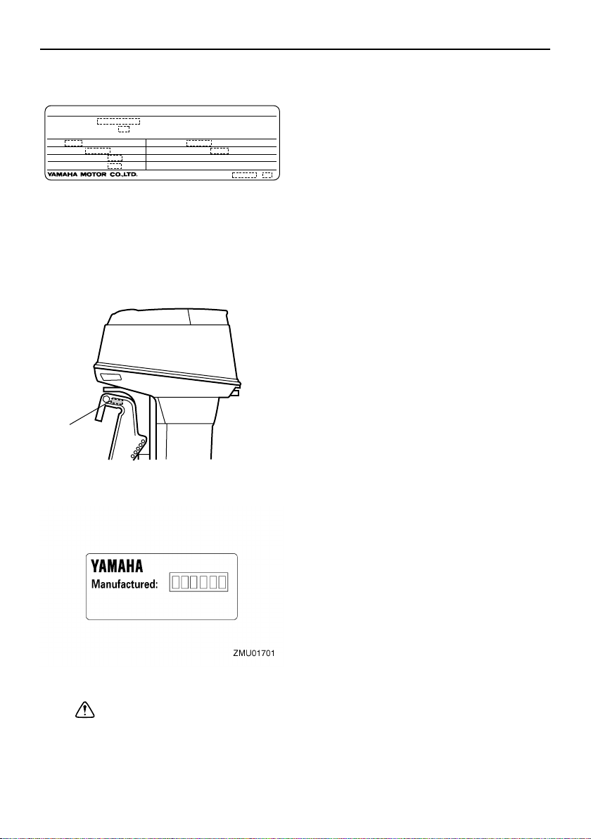
Identification numbers record........... 1
Outboard motor serial number .......... 1
Key number....................................... 1
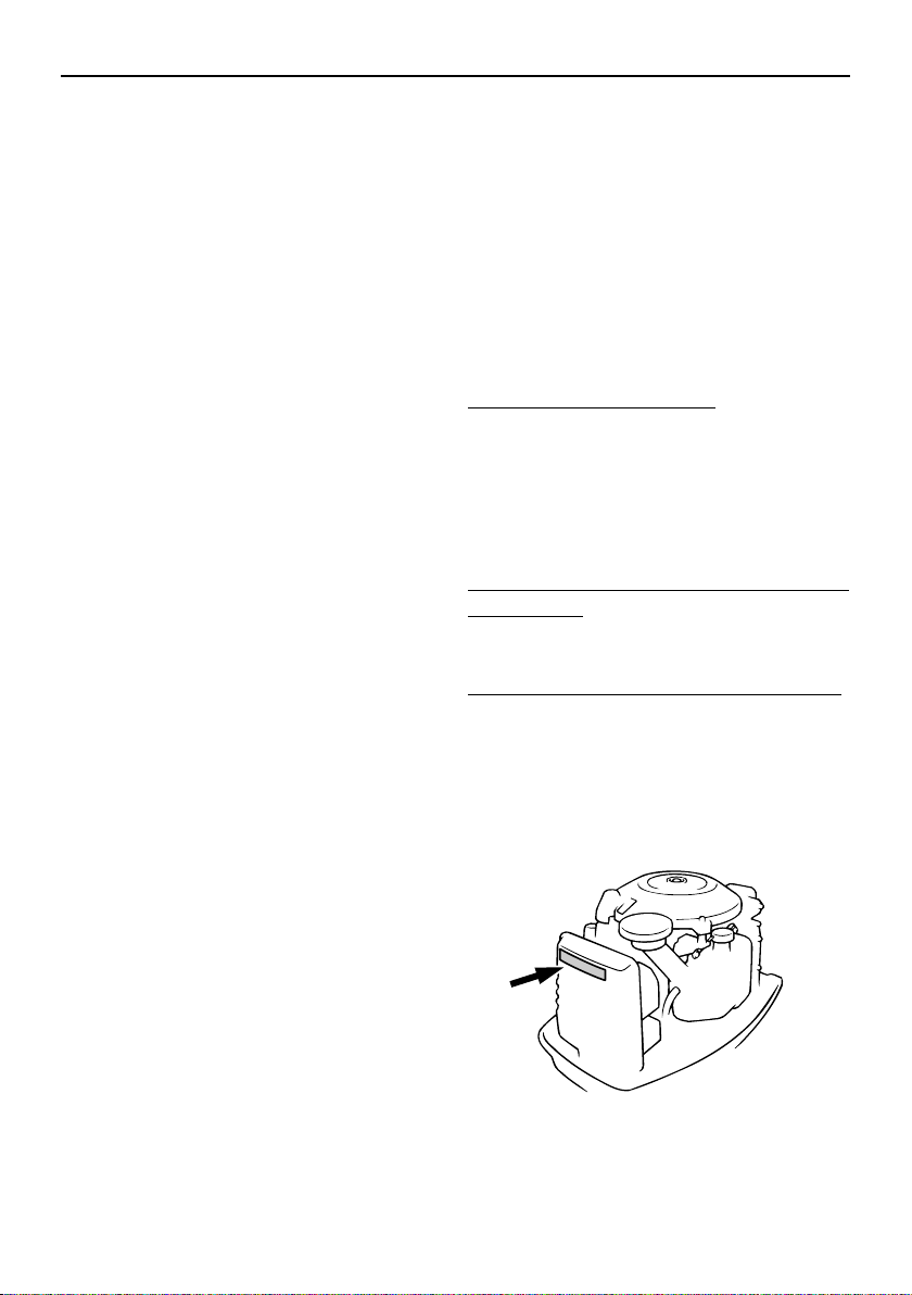
Emission control information ............ 1
North American models..................... 1
Safety information ............................ 2
Important labels................................ 3
Warning labels .................................. 3
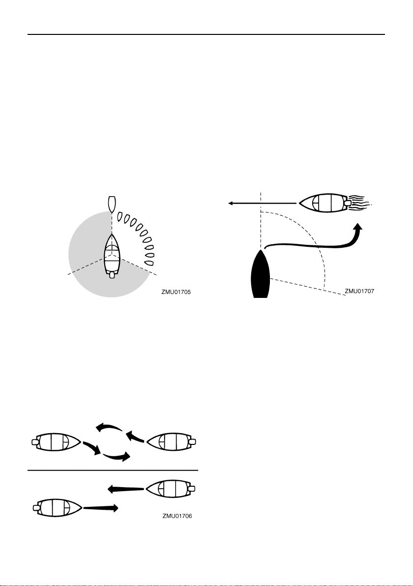
Basic boating rules
(Rules of the road) ......................... 4
Steering and sailing rules and
sound signals.................................. 4
Rules when encountering vessels .... 4
Other special situations..................... 5
Fueling instructions .......................... 7
Gasoline............................................ 8
Engine oil .......................................... 8
Battery requirement.......................... 8
Battery specifications ........................ 8
Propeller selection............................ 8
Start-in-gear protection .................... 9
Basic components .......................... 10
Main components........................... 10
Fuel tank ......................................... 10
Fuel joint ......................................... 11
Fuel gauge ...................................... 11
Fuel tank cap .................................. 11
Air vent screw ................................. 11
Remote control................................ 11
Remote control lever....................... 11
Neutral interlock trigger................... 12
Neutral throttle lever........................ 12
Tiller handle .................................... 12
Gear shift lever................................ 12
Throttle grip..................................... 13
Throttle indicator ............................. 13
Throttle friction adjuster................... 13
Engine stop lanyard switch ............. 14
Engine stop button .......................... 14
Main switch ..................................... 15
Power trim and tilt switch on
remote control or tiller handle ....... 15
Power trim and tilt switch on
bottom engine cowling .................. 16
Trim tab with anode.........................16
Trim rod (tilt pin) .............................. 17
Tilt support lever for power trim
and tilt or hydro tilt model..............17
Top cowling lock lever(s)
(turn type)...................................... 17
Tachometer ..................................... 18
Digital tachometer ........................... 18
Oil level indicators
(three indicators 2) ........................18
Oil level indicator (digital type) ........ 18
Overheat warning indicator
(digital type) .................................. 19
Trim meter ....................................... 19
Trim meter (digital type) .................. 19
Hour meter (digital type)..................19
Warning system ............................. 20
Overheat warning ............................ 20
Oil level warning and oil filter
clogging warning ........................... 21
Operation ......................................... 23
Installation...................................... 23
Mounting the outboard motor .......... 23
Clamping the outboard motor..........24
Breaking in engine ......................... 25
Gasoline and engine oil mixing
chart (50:1).................................... 25
Procedure for oil injection models ... 25
Preoperation checks ...................... 26
Fuel ................................................. 26
Oil .................................................... 26
Controls ........................................... 26
Engine ............................................. 26
Operation after a long period of
storage .......................................... 26
Filling fuel and engine oil ............... 27
Filling fuel for portable tank ............. 27
Ring Free Fuel Additive...................27
Filling oil for electric start models .... 28
Oil level indicator operation............. 29
Operating engine ........................... 29
Feeding fuel (portable tank) ............29
Starting engine ................................ 30
Warming up engine........................ 33
Electric start and prime start
✩✦✯✬✤✲✲✣ ✤

Table of contents
models .......................................... 33
Shifting ........................................... 33
Forward (tiller handle and remote
control models) ............................. 33
Reverse (automatic reverse lock
and power trim and tilt models)..... 34
Stopping engine ............................. 34
Procedure ....................................... 35
Trimming outboard motor............... 35
Adjusting trim angle ........................ 36
Adjusting boat trim .......................... 37
Tilting up and down ........................ 37
Procedure for tilting up.................... 38
Procedure for tilting down ............... 39
Cruising in shallow water ...............40
Power trim and tilt models /
power tilt models........................... 40
Cruising in other conditions............ 41
Maintenance..................................... 42
Specifications ................................. 42
Transporting and storing outboard
motor ............................................ 43
Clamp screw mounting models....... 43
Storing outboard motor ................... 43
Procedure ....................................... 44
Lubrication (oil injection models)..... 45
Cleaning and anticorrosion
measures ...................................... 45
Battery care..................................... 45
Cleaning the outboard motor .......... 46
Checking painted surface of
motor............................................. 46
Periodic maintenance..................... 46
Replacement parts.......................... 46
Maintenance chart .......................... 47
Greasing ......................................... 49
Cleaning and adjusting spark
plug ............................................... 49
Checking fuel system...................... 50
Inspecting fuel filter ......................... 51
Cleaning fuel filter ........................... 51
Inspecting idling speed ................... 52
Checking water in engine oil tank ... 52
Checking wiring and connectors ..... 52
Exhaust leakage ............................. 53
Water leakage ................................. 53
Checking power trim and tilt /
power tilt system ........................... 53
Checking propeller .......................... 53
Removing the propeller ................... 54
Installing the Propeller.....................55
Changing gear oil ............................ 55
Cleaning fuel tank ...........................56
Inspecting and replacing
anode(s)........................................ 57
Checking battery
(for electric start models) ..............57
Connecting the battery .................... 58
Disconnecting the battery................59
Checking top cowling ......................59
Coating the boat bottom.................. 59
Trouble Recovery............................ 60
Troubleshooting ............................. 60
Temporary action in emergency .... 63
Impact damage ............................... 63
Replacing fuse ................................ 63
Power trim and tilt / power tilt will
not operate.................................... 64
Starter will not operate .................... 64
Emergency starting engine .............65
Engine fails to operate ................... 66
Cold engine fails to start..................66
Treatment of submerged motor ..... 67
Procedure........................................ 67
Consumer information ................... 69
Important warranty information for
U.S.A. and Canada...................... 69
YAMAHA MOTOR
CORPORATION, U.S.A.
OUTBOARD MOTOR TWO
YEAR LIMITED WARRANTY ...... 71
IMPORTANT WARRANTY
INFORMATION IF YOU USE
YOUR YAMAHA OUTSIDE
THE USA OR CANADA............... 74
✩✦✯✬✤✲✲✣ ✥

1
General information
EMU25170
Identification numbers record
EMU25182
Outboard motor serial number
The outboard motor serial number is
stamped on the label attached to the port
side of the clamp bracket or the upper part of
the swivel bracket.
Record your outboard motor serial number in
the spaces provided to assist you in ordering
spare parts from your Yamaha dealer or for
reference in case your outboard motor is sto-
len.
EMU25190
Key number
If a main key switch is equipped with the mo-
tor, the key identification number is stamped
on your key as shown in the illustration.
Record this number in the space provided for
reference in case you need a new key.
EMU25221
Emission control information
EMU25230
North American models
This engine conforms to U.S. Environmental
Protection Agency (EPA) regulations for ma-
rine SI engines. See the label affixed to your
engine for details.
EMU30390
Approval label of emission control certif-
icate
This label is attached to the bottom cowling.
Existing Technology; N/A
1. Outboard motor serial number location
1
ZMU02931
1. Key number
1. Approval label location
1
ZMU05002
✩✦✯✬✤✲✲✣ ✤

General information
2
EMU25262
Manufactured date label
This label is attached to the clamp bracket or
the swivel bracket.
EMU25362
Safety information
●
Before mounting or operating the outboard
motor, read this entire manual. Reading it
should give you an understanding of the
motor and its operation.
●
Before operating the boat, read any own-
er’s or operator’s manuals supplied with it
and all labels. Be sure you understand
each item before operating.
●
Do not overpower the boat with this out-
board motor. Overpowering the boat could
result in loss of control. The rated power of
the outboard should be equal to or less
than the rated horsepower capacity of the
boat. If the rated horsepower capacity of
the boat is unknown, consult the dealer or
boat manufacturer.
●
Do not modify the outboard. Modifications
could make the motor unfit or unsafe to
use.
●
Incorrect propeller selection and incorrect
use may not only cause engine damage,
but also adversely affect fuel consumption.
Consult your dealer for correct use.
●
Never operate after drinking alcohol or tak-
ing drugs. About 50% of all boating fatali-
ties involve intoxication.
●
Have an approved personal flotation de-
vice (PFD) on board for every occupant. It
is a good idea to wear a PFD whenever
boating. At a minimum, children and non-
swimmers should always wear PFDs, and
everyone should wear PFDs when there
are potentially hazardous boating condi-
tions.
●
Gasoline is highly flammable, and its va-
pors are flammable and explosive. Handle
and store gasoline carefully. Make sure
there are no gas fumes or leaking fuel be-
fore starting the engine.
●
This product emits exhaust gases which
contain carbon monoxide, a colorless,
odorless gas which may cause brain dam-
age or death when inhaled. Symptoms in-
1. Manufactured date label location
EMISSION CONTROL INFORMATION
ENGINE FAMILY :
THIS ENGINE CONFORMS TO 2001 U.S. EPA REGULATIONS FOR MARINE SI ENGINES.
REFER TO THE OWNERS MANUAL FOR MAINTENANCE SPECIFICATIONS AND ADJUSTMENTS.
FELs :
SPARK PLUG :
DISPLACEMENT :
ADVERTISED POWER :
IDLE SPEED :
SPARK PLUG GAP (mm) :
FUEL : GASOLINE
VALVE LASH (mm) : IN : N/A EX : N/A
cm
kW
g/kW-hr rpm IN NEUTRAL
3
ZMU05230
1
ZMU04129
✩✦✯✬✤✲✲✣ ✥

General information
3
clude nausea, dizziness, and drowsiness.
Keep cockpit and cabin areas well ventilat-
ed. Avoid blocking exhaust outlets.
●
Check throttle, shift, and steering for prop-
er operation before starting the engine.
●
Attach the engine stop switch lanyard cord
to a secure place on your clothing, or your
arm or leg while operating. If you acciden-
tally leave the helm, the cord will pull from
the switch, stopping the engine.
●
Know the marine laws and regulations
where you will be boating—and obey
them. For basic boating rules, see “Rules
of the road”on page 4.
●
Stay informed about the weather. Check
weather forecasts before boating. Avoid
boating in hazardous weather.
●
Tell someone where you are going: leave
a Float Plan with a responsible person. Be
sure to cancel the Float Plan when you re-
turn.
●
Use common sense and good judgment
when boating. Know your abilities, and be
sure you understand how your boat han-
dles under the different boating conditions
you may encounter. Operate within your
limits, and the limits of your boat. Always
operate at safe speeds, and keep a careful
watch for obstacles and other traffic.
●
Always watch carefully for swimmers dur-
ing the engine operation.
●
Stay away from swimming areas.
●
When a swimmer is in the water near you
shift into neutral and shut off the engine.
●
Do not illegally discard empty containers
used to replace or replenish oil. For the
correct processing of empty containers,
consult the dealer where you purchased
the oil.
●
When replacing oils used to lubricate the
product (engine or gear oil), be sure to
wipe away any spilt oil. Never pour oil with-
out using a funnel or similar device. If nec-
essary, verify the necessary replacement
procedure with the dealer.
●
Never illegally discard (dump) the product.
Yamaha recommends consulting the deal-
er on discarding the product.
Be informed about boating safety. Additional
publications and information can be obtained
from many organizations, including the fol-
lowing:
United States Coast Guard
Consumer Affairs Staff (G-BC)
Office of Boating, Public, and Consumer Af-
fairs
U.S. Coast Guard Headquarters
Washington, D.C. 20593-0001
Boating Safety Hotline: 1-800-368-5647
National Marine Manufacturers Associa-
tion (NMMA)
401 N. Michigan Ave.
Chicago, Il 60611
Marine Retailers Association of America
155 N. Michigan Ave.
Chicago, Il 60601
EMU25382
Important labels
EMU25395
Warning labels
ZMU03342
✩✦✯✬✤✲✲✣ ✦

General information
4
EMU25401
Label
WARNING
EWM01260
●
Be sure shift control is in neutral before
starting engine. (except 2HP)
●
Do not touch or remove electrical parts
when starting or during operation.
●
Keep hands, hair, and clothes away
from flywheel and other rotating parts
while engine is running.
EMU25500
Basic boating rules (Rules of
the road)
Just as there are rules which apply when you
are driving on streets and high ways, there
are waterway rules which apply when you
are driving your boat. These rules are used
internationally, and are also enforced by the
United States Coast Guard and local agen-
cies. You should be aware of these rules,
and follow them whenever you encounter
another vessel on the water.
Several sets of rules prevail according to
geographic location, but are all basically the
same as the International Rules of the Road.
The rules presented here in your Owner’s
Manual are condensed, and have been pro-
vided for your convenience only. Consult
your local U.S. Coast Guard Auxiliary or De-
partment of Motor Vehicles for a complete
set of rules governing the waters in which
you will be using your boat.
EMU25510
Steering and sailing rules and sound
signals
Whenever two vessels on the water meet
one another, one vessel has the right-of-
way; it is called the “stand-on”vessel. The
vessel which does not have the right-of-way
is called the “give-way”or “burdened”vessel.
These rules determine which vessel has the
right-of-way, and what each vessel should
do.
Stand-on vessel
The vessel with the right-of-way has the duty
to continue its course and speed, except to
avoid an immediate collision. When you
maintain your direction and speed, the other
vessel will be able to determine how best to
avoid you.
Give-way vessel
The vessel which does not have the right-of-
way has the duty to take positive and timely
action to stay out of the way of the Stand-On
vessel. Normally, you should not cross in
front of the vessel with the right-of-way. You
should slow down or change directions brief-
ly and pass behind the other vessel. You
should always move in such a way that the
operator of the other vessel can see what
you are doing.
“The general prudential rule”
This rule is called Rule 2 in the International
Rules and says,
“In obeying and construing these rules due
regard shall be had to all dangers of naviga-
tion and collision, and to any special circum-
stances, which may render a departure from
the above rules necessary in order to avoid
immediate danger.”
In other words, follow the standard rules ex-
cept when a collision will occur unless both
vessels try to avoid each other. If that is the
case, both vessels become “Give-Way”ves-
sels.
EMU25520
Rules when encountering vessels
There are three main situations which you
may encounter with other vessels which
could lead to a collision unless the Steering
Rules are followed:
Meeting:
(you are approaching another ves-
✩✦✯✬✤✲✲✣ ✧

General information
5
sel head-on)
Crossing:
(you are traveling across the oth-
er vessel’s path)
Overtaking:
(you are passing or being
passed by another vessel)
In the following illustration, your boat is in the
center. You should give the right-of-way to
any vessels shown in white area (you are the
Give-Way vessel). Any vessels in the shad-
ed area must yield to you (they are the Give-
Way vessels). Both you and the meeting
vessel must alter course to avoid each other.
Meeting
If you are meeting another power vessel
head on, and are close enough to run the risk
of collision, neither of you has the right-of-
way! Both of you should alter course to avoid
an accident. You should keep the other ves-
sel on your port (left) side. This rule doesn’t
apply if both of you will clear one another if
you continue on your set course and speed.
Crossing
When two power driven vessels are crossing
each other’s path close enough to run the
risk of collision, the vessel which has the oth-
er on the starboard (right) side must keep out
of the way of the other. If the other vessel is
on your right, you must keep out of its way;
you are the Give-Way vessel. If the other
vessel is on your port (left) side, remember
that you should maintain course and direc-
tion, provided the other vessel gives you the
right-of-way as it should.
Overtaking
If you are passing another vessel, you are
the “Give-Way”vessel. This means that the
other vessel is expected to maintain its
course and speed. You must stay out of its
way until you are clear of it. Likewise, if an-
other vessel is passing you, you should
maintain your speed and direction so that the
other vessel can steer itself around you.
EMU25530
Other special situations
There are three other rules you should be
aware of when driving your boat around oth-
er vessels.
Narrow channels and bends
When navigating in narrow channels, you
should keep to the right when it is safe and
practical to do so. If the operator of a power-
driven vessel is preparing to go around a
✩✦✯✬✤✲✲✣

General information
6
bend that may obstruct the view of other wa-
ter vessels, the operator should sound a pro-
longed blast on the whistle (4 to 6 seconds).
If another vessel is around the bend, it too
should sound the whistle. Even if no reply is
heard, however, the vessel should still pro-
ceed around the bend with caution. If you
navigate such waters with your boat, you will
need to carry a portable air horn, available
from local marine supply stores.
Fishing vessel right-of-way
All vessels which are fishing with nets, lines
or trawls are considered to be “fishing ves-
sels”under the International Rules. Vessels
with trolling lines are not considered fishing
vessels. Fishing vessels have the right-of-
way regardless of position. Fishing vessels
cannot, however, impede the passage of
other vessels in narrow channels.
Sailing vessel right-of-way
Sailing vessels should normally be given the
right-of-way. The exceptions to this are:
1. When the sailing vessel is overtaking
the power-driven vessel, the power-driv-
en vessel has the right-of-way.
2. Sailing vessels should keep clear of any
fishing vessel.
3. In a narrow channel, a sailing vessel
should not hamper the safe passage of
a power-driven vessel which can navi-
gate only in such a channel.
Reading buoys and other markers
The waters of the United states are marked
for safe navigation by the lateral system of
buoyage. Simply put, buoys and markers
have an arrangement of shapes, colors,
numbers and lights to show which side of the
buoy a boater should pass on when navigat-
ing in a particular direction. The markings on
these buoys are oriented from the perspec-
tive of being entered from seaward (the boat-
er is going towards the port). This means that
red buoys are passed on the starboard
(right) side when proceeding from open wa-
ter into port, and black buoys are to port (left)
side. When navigating out of port, your posi-
tion with respect to the buoys should be re-
versed; red buoys should be to port and
black buoys to starboard.
Many bodies of water used by boaters are
entirely within the boundaries of a particular
state. The Uniform State Waterway Marking
System has been devised for these waters.
This system uses buoys and signs with dis-
tinctive shapes and colors to show regulato-
ry or advisory information. These markers
are white with black letters and orange
boarders. They signify speed zones, restrict-
ed areas, danger areas, and general infor-
mation.
Remember, markings may vary by geo-
graphic location. Always consult local boat-
ing authorities before driving your boat in
unfamiliar waters.
✩✦✯✬✤✲✲✣ ✩

General information
7
EMU25540
Fueling instructions
WARNING
EWM00010
GASOLINE AND ITS VAPORS ARE HIGH-
LY FLAMMABLE AND EXPLOSIVE!
●
Do not smoke when refueling, and keep
away from sparks, flames, or other
sources of ignition.
●
Stop engine before refueling.
●
Refuel in a well-ventilated area. Refuel
portable fuel tanks off the boat.
●
Take care not to spill gasoline. If gaso-
line spills, wipe it up immediately with
ZMU01708
✩✦✯✬✤✲✲✣ ✪

General information
8
dry rags.
●
Do not overfill the fuel tank.
●
Tighten the filler cap securely after re-
fueling.
●
If you should swallow some gasoline,
inhale a lot of gasoline vapor, or get
gasoline in your eyes, get immediate
medical attention.
●
If any gasoline spills onto your skin, im-
mediately wash with soap and water.
Change clothing if gasoline spills on it.
●
Touch the fuel nozzle to the filler open-
ing or funnel to help prevent electro-
static sparks.
CAUTION:
ECM00010
Use only new clean gasoline which has
been stored in clean containers and is not
contaminated with water or foreign mat-
ter.
EMU25570
Gasoline
If knocking or pinging occurs, use a different
brand of gasoline or premium unleaded fuel.
Gasohol
There are two types of gasohol: gasohol con-
taining ethanol and that containing metha-
nol. Gasohol containing ethanol can be used
if ethanol content does not exceed 10% and
the fuel meets minimum octane ratings.
Yamaha does not recommended gasohol
containing methanol because it can cause
fuel system damage or engine performance
problems.
EMU25650
Engine oil
If the recommended engine oil is not avail-
able, another 2-stroke engine oil with an
NMMA-certified TC-W3 rating may be used.
EMU25690
Battery requirement
CAUTION:
ECM01060
Do not use a battery that does not meet
the specified capacity. If a battery which
does not meet specifications is used, the
electric system could perform poorly or
be overloaded, causing electric system
damage.
For electric start models, choose a battery
which meets the following specifications.
EMU25711
Battery specifications
EMU25742
Propeller selection
The performance of your outboard motor will
be critically affected by your choice of propel-
ler, as an incorrect choice could adversely
affect performance and could also seriously
damage the motor. Engine speed depends
on the propeller size and boat load. If engine
Recommended gasoline:
Regular unleaded gasoline with a min-
imum octane rating of 86 (Pump Oc-
tane Number) = (R+M)/2
Recommended engine oil:
YAMALUBE 2-stroke outboard motor
oil
Minimum cold cranking amps (CCA/
SAE):
245.0 A
Minimum marine cranking amps (MCA/
ABYC):
323.0 A
Minimum reserve capacity (RC/SAE):
52 minutes
✩✦✯✬✤✲✲✣ ✫

General information
9
speed is too high or too low for good engine
performance, this will have an adverse effect
on the engine.
Yamaha outboard motors are fitted with pro-
pellers chosen to perform well over a range
of applications, but there may be uses where
a propeller with a different pitch would be
more appropriate. For a greater operating
load, a smaller-pitch propeller is more suit-
able as it enables the correct engine speed
to be maintained. Conversely, a larger-pitch
propeller is more suitable for a smaller oper-
ating load.
Yamaha dealers stock a range of propellers,
and can advise you and install a propeller on
your outboard that is best suited to your ap-
plication.
NOTE:
Select a propeller which will allow the engine
to reach the middle or upper half of the oper-
ating range at full throttle with the maximum
boat load. If operating conditions such as
light boat loads then allow the engine r/min to
rise above the maximum recommended
range, reduce the throttle setting to maintain
the engine in the proper operating range.
For instructions on propeller removal and in-
stallation, see page 53.
EMU25770
Start-in-gear protection
Yamaha outboard motors or Yamaha-ap-
proved remote control units are equipped
with start-in-gear protection device(s). This
feature permits the engine to be started only
when it is in neutral. Always select neutral
before starting the engine.
1. Propeller diameter in inches
2. Propeller pitch in inches
3. Type of propeller (propeller mark)
ZMU04606
-
x
123
✩✦✯✬✤✲✲✣ ✬

10
Basic components
EMU25796
Main components
NOTE:
* May not be exactly as shown; also may not be included as standard equipment on all mod-
els.
40, 50
EMU25802
Fuel tank
If your model was equipped with a portable
fuel tank, its function is as follows.
WARNING
EWM00020
The fuel tank supplied with this engine is
its dedicated fuel reservoir and must not
be used as a fuel storage container. Com-
mercial users should conform to relevant
licensing or approval authority regula-
11
14 15
12 13
1
2
4
3
5
6
2
7
8
9
10
ZMU05014
1. Battery cable
2. Anode(s)
3. Propeller*
4. Cooling water inlet
5. Trim tab (anode)
6. Anti-cavitation plate
7. Trim rod
8. Clamp bracket
9. Tilt support lever
10. Top cowling
11. Remote control box (side mount type)*
12. Digital tachometer*
13. Tachometer*
14. Trim meter*
15. Fuel tank*
✩✦✯✬✤✲✲✣ ✤✣

Basic components
11
tions.
EMU25830
Fuel joint
This joint is used to connect the fuel line.
EMU25841
Fuel gauge
This gauge is located on either the fuel tank
cap or on the fuel joint base. It shows the ap-
proximate amount of fuel remaining in the
tank.
EMU25850
Fuel tank cap
This cap seals the fuel tank. When removed,
the tank can be filled with fuel. To remove the
cap, turn it counterclockwise.
EMU25860
Air vent screw
This screw is on the fuel tank cap. To loosen
the screw, turn it counterclockwise.
EMU26180
Remote control
The remote control lever actuates both the
shifter and the throttle. The electrical switch-
es are mounted on the remote control box.
EMU26190
Remote control lever
Moving the lever forward from the neutral po-
sition engages forward gear. Pulling the le-
ver back from neutral engages reverse. The
engine will continue to run at idle until the le-
ver is moved about 35°(a detent can be felt).
Moving the lever farther opens the throttle,
and the engine will begin to accelerate.
1. Fuel joint
2. Fuel gauge
3. Fuel tank cap
4. Air vent screw
ZMU03157
13
42
1. Power trim and tilt switch
2. Remote control lever
3. Neutral interlock trigger
4. Neutral throttle lever
5. Main switch / choke switch
6. Engine stop lanyard switch
7. Throttle friction adjuster
1. Neutral “”
2. Forward “”
3. Reverse “”
4. Shift
5. Fully closed
✩✦✯✬✤✲✲✣ ✤✤

Basic components
12
EMU26201
Neutral interlock trigger
To shift out of neutral, first pull the neutral in-
terlock trigger up.
EMU26211
Neutral throttle lever
To open the throttle without shifting into ei-
ther forward or reverse, put the remote con-
trol lever in the neutral position and lift the
neutral throttle lever.
NOTE:
The neutral throttle lever will operate only
when the remote control lever is in neutral.
The remote control lever will operate only
when the neutral throttle lever is in the closed
position.
EMU25911
Tiller handle
To change direction, move the tiller handle to
the left or right as necessary.
EMU25922
Gear shift lever
Pulling the gear shift lever towards you puts
the engine in forward gear so that the boat
moves ahead. Pushing the lever away from
you puts the engine in reverse gear so that
the boat moves astern.
6. Throttle
7. Fully open
1. Neutral interlock trigger
1. Fully open
2. Fully closed
✩✦✯✬✤✲✲✣ ✤✥

Basic components
13
EMU25941
Throttle grip
The throttle grip is on the tiller handle. Turn
the grip counterclockwise to increase speed
and clockwise to decrease speed.
EMU25961
Throttle indicator
The fuel consumption curve on the throttle
indicator shows the relative amount of fuel
consumed for each throttle position. Choose
the setting that offers the best performance
and fuel economy for the desired operation.
EMU25970
Throttle friction adjuster
A friction device provides adjustable resis-
tance to movement of the throttle grip or the
remote control lever, and can be set accord-
ing to operator preference.
To increase resistance, turn the adjuster
clockwise. To decrease resistance, turn the
adjuster counterclockwise.
WARNING
EWM00030
Do not overtighten the friction adjuster. If
there is too much resistance, it could be
difficult to move throttle lever or grip,
which could result in an accident.
1. Forward “”
2. Neutral “”
3. Reverse “”
1. Throttle indicator
ZMU03095
✩✦✯✬✤✲✲✣ ✤✦

Basic components
14
When constant speed is desired, tighten the
adjuster to maintain the desired throttle set-
ting.
EMU25990
Engine stop lanyard switch
The lock plate must be attached to the en-
gine stop switch for the engine to run. The
lanyard should be attached to a secure place
on the operator’s clothing, or arm or leg.
Should the operator fall overboard or leave
the helm, the lanyard will pull out the lock
plate, stopping ignition to the engine. This
will prevent the boat from running away un-
der power.
WARNING
EWM00120
●
Attach the engine stop switch lanyard
to a secure place on your clothing, or
your arm or leg while operating.
●
Do not attach the lanyard to clothing
that could tear loose. Do not route the
lanyard where it could become entan-
gled, preventing it from functioning.
●
Avoid accidentally pulling the lanyard
during normal operation. Loss of en-
gine power means the loss of most
steering control. Also, without engine
power, the boat could slow rapidly. This
could cause people and objects in the
boat to be thrown forward.
NOTE:
The engine cannot be started with the lock
plate removed.
EMU26001
Engine stop button
To open the ignition circuit and stop the en-
gine, push this button.
1. Lanyard
2. Lock plate
1. Lanyard
2. Lock plate
✩✦✯✬✤✲✲✣ ✤✧

Basic components
15
EMU26090
Main switch
The main switch controls the ignition system;
its operation is described below.
●
“”
(off)
With the main switch in the “”(off) posi-
tion, the electrical circuits are off, and the key
can be removed.
●
“”
(on)
With the main switch in the “”(on) posi-
tion, the electrical circuits are on, and the key
cannot be removed.
●
“”
(start)
With the main switch in the “”(start) po-
sition, the starter motor turns to start the en-
gine. When the key is released, it returns
automatically to the “”(on) position.
EMU26141
Power trim and tilt switch on remote
control or tiller handle
The power trim and tilt system adjusts the
outboard motor angle in relation to the tran-
som. Pressing the switch “”(up) trims the
outboard motor up, then tilts it up. Pressing
the switch “”(down) tilts the outboard mo-
tor down and trims it down. When the switch
is released, the outboard motor will stop in its
current position.
NOTE:
For instructions on using the power trim and
tilt switch, see pages 35 and 37.
✩✦✯✬✤✲✲✣ ✤
Other manuals for 40
1
This manual suits for next models
1
Table of contents
Other Yamaha Outboard Motor manuals