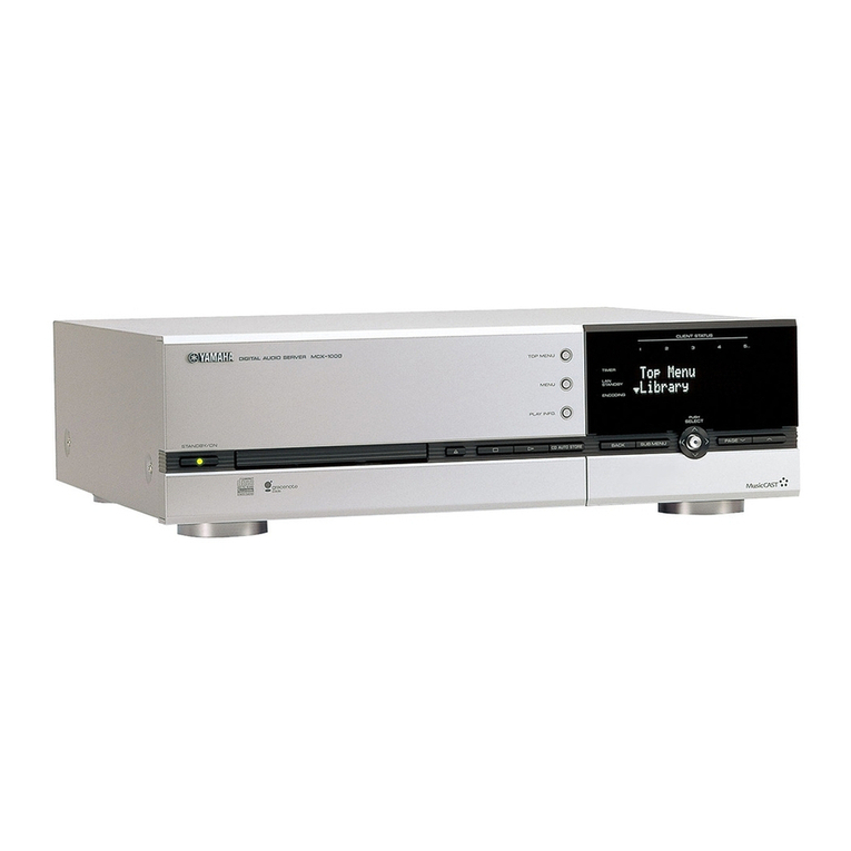
Yamaha MCX 1000 - MusicCAST - Digital Audio Server User manual

MCX-1000
TheMusicCASTsystemconsistsoftheMCX-1000,the
MCX-A10andtheMCX-SP10.
ThisservicemanualisfortheMCX-1000.
FortheMCX-A10andtheMCX-SP10servicemanual,
pleaserefertothefollowingpublicationnumber:
MCX-A10/MCX-SP10 100852
Whenacceptingarepairorderfromtheuser,besureto
informhim/herthatthedatainHDDcannotbeguaranteed.
Fortherepairwork,itisrecommendedtoreceiveMCX-
1000andMCX-A10asaset.
ミュージックキャストシステムはMCX-1000、MCX-A10
およびMCX-SP10で構成されています。
このサービスマニュアルはMCX-1000用です。
MCX-A10およびMCX-SP10のサービスマニュアルは下記
を参照してください。
MCX-A10/MCX-SP10 100852
修理依頼を受ける際、HDDのデータは保証できないことを
お客様に伝えてください。
修理品はMCX-1000とMCX-A10をセットでお預かりする
ことを推奨します。
IMPORTANT NOTICE
This manual has been provided for the use of authorized YAMAHA Retailers and their service personnel.
It has been assumed that basic service procedures inherent to the industry, and more specifically YAMAHA Products, are already known and understood by the users,
and have therefore not been restated.
WARNING: Failure to follow appropriate service and safety procedures when servicing this product may result in personal injury, destruction of expensive
components, and failure of the product to perform as specified. For these reasons, we advise all YAMAHA product owners that any service required
should be performed by an authorized YAMAHA Retailer or the appointed service representative.
IMPORTANT: The presentation or sale of this manual to any individual or firm does not constitute authorization, certification or recognition of any applicable
technical capabilities, or establish a principle-agent relationship of any form.
The data provided is believed to be accurate and applicable to the unit(s) indicated on the cover. The research, engineering, and service departments of YAMAHA are
continually striving to improve YAMAHA products. Modifications are, therefore, inevitable and specifications are subject to change without notice or obligation to
retrofit. Should any discrepancy appear to exist, please contact the distributor's Service Division.
WARNING: Static discharges can destroy expensive components. Discharge any static electricity your body may have accumulated by grounding yourself to the
ground buss in the unit (heavy gauge black wires connect to this buss).
IMPORTANT: Turn the unit OFF during disassembly and part replacement. Recheck all work before you apply power to the unit.
100851
P.O.Box 1, Hamamatsu, Japan
SERVICE MANUAL
DIGITAL AUDIO SERVER
MCX-1000

MCX-1000
2
MCX-1000
WALL
OUTLET EQUIPMENT
UNDER TEST
AC LEAKAGE
TESTER OR
EQUIVALENT
INSULATING
TABLE
■TO SERVICE PERSONNEL
1. Critical Components Information
Components having special characteristics are marked s
and must be replaced with parts having specifications equal
to those originally installed.
2. Leakage Current Measurement (For 120V Models Only)
When service has been completed, it is imperative to verify
that all exposed conductive surfaces are properly insulated
from supply circuits.
●Meter impedance should be equivalent to 1500 ohm shunted
by 0.15µF.
●Leakage current must not exceed 0.5mA.
●Be sure to test for leakage with the AC plug in both polarities.
WARNING: CHEMICAL CONTENT NOTICE!
The solder used in the production of this product contains LEAD. In addition, other electrical/electronic and /or plastic
(where applicable) components may also contain traces of chemicals found by the California Health and Welfare Agency
(and possibly other entities) to cause cancer and/or birth defects or other reproductive harm.
DO NOT PLACE SOLDER, ELECTRICAL/ELECTRONIC OR PLASTIC COMPONENTS IN YOUR MOUTH FOR ANY REA-
SON WHATSOEVER!
Avoid prolonged, unprotected contact between solder and your skin! When soldering, do not inhale solder fumes or expose
eyes to solder/flux vapor!
If you come in contact with solder or components located inside the enclosure of this product, wash your hands before
handling food.
“CAUTION”
“F400: FOR CONTINUED PROTECTION AGAINST RISK OF FIRE, REPLACE ONLY WITH SAME TYPE 10A, 250V FUSE.”
CAUTION
F400: REPLACE WITH SAME TYPE 10A, 250V FUSE.
ATTENTION
F400: UTILISER UN FUSIBLE DE RECHANGE DE MEME TYPE DE 10A, 250V.
THE COMPACT DISC RECORDER SHOULD NOT BE ADJUSTED OR REPAIRED BY ANYONE EXCEPT PROPERLY QUALIFIED
SERVICE PERSONNEL.
■CONTENTS
TO SERVICE PERSONNEL ...................................... 2~4
PREVENTION OF ELECTRO STATIC DISCHARGE... 5
FRONT PANEL .............................................................. 6
REAR PANELS .......................................................... 6~7
REMOTE CONTROL PANEL ........................................ 7
SPECIFICATIONS...................................................... 8~9
INTERNAL VIEW ........................................................... 9
DISASSEMBLY PROCEDURES / 分解手順.......... 10~15
SERVICE PRECAUTIONS/
サービス時の注意事項 .................................................. 16
UPDATING FIRMWARE/
ファームウェアのアップデート ............................. 16~18
RECOVERY AFTER REPLACING HDD/
HDD交換後のリカバリー........................................ 18~19
RECOVERY AFTER REPLACING MAIN P.C.B./
MAINP.C.B.交換後のリカバリー .......................... 20~21
SERVICE MENU/サービスメニュー .................... 21~22
ENTERING SYSTEM ID/
システムIDの書き込み ............................................ 23~24
TROUBLESHOOTING/
トラブルシューティング ........................................ 25~26
TEST MODE/テストモード ................................. 27~28
DISPLAY DATA ........................................................... 29
IC DATA ................................................................. 30~55
BLOCK DIAGRAM................................................. 56~57
PRINTED CIRCUIT BOARD .................................. 58~63
PIN CONNECTION DIAGRAM .................................... 64
SCHEMATIC DIAGRAM ........................................ 65~73
PARTS LIST........................................................... 75~89
REMOTE CONTROL.................................................... 90
DIRECTION FOR USE
SETUP GUIDE ................................................... 90~93
QUICK MANUAL ............................................. 94~112

MCX-1000
3
MCX-1000
Laser Radiation Point
WARNING: Laser Safety
This product contains a laser beam component. This component may emit invisible, as well as visible radiation, which may
cause eye damage. To protect your eyes and skin from laser radiation, the following precautions must be used during
servicing of the unit.
1) When testing and/or repairing any component within the product, keep your eyes and skin more than 30 cm away from
the laser pick-up unit at all times. Do not stare at the laser beam at any time.
2) Do not attempt to readjust, disassemble or repair the laser pick-up, unless noted elsewhere in this manual.
3) CAUTION: Use of controls, adjustments or performance of procedures other than those specified herein may result in
hazardous radiation exposure.
Laser Emitting conditions:
1. This device is a Class IIIb laser device.
Class IIIb means
With the protective case removed, exposure to the light output from the laser, either directly or reflected by a mirror, can
cause harm to the eyes, but there is no danger to the eyes from exposure to dispersed reflected laser light. (Generally 0.5
W or less)
2. Always wear eyeglasses designed for protection against laser light.
3. Always wear gloves.
4. Have no reflective objects anywhere near this device.
5. Figure A shows from where in this device the laser is emitted.
6. When switching on the power to the device for the first time, always measure the laser power with a laser power meter
and check that the power is no greater than the number of Watts in the specifications.
7. Never look directly at the laser light while the laser is emitting light.
8. Do not allow the laser light to shine directly on your skin while the laser is emitting light.
PROTECTION OF EYES FROM LASER BEAM DURING SERVICING
This set employs a laser. Therefore, be sure to carefully
follow the instructions below when servicing.
1. Laser Diode Properties
• Material : GaAlAs
• Wavelength : 779-789 nm
• Emission Duration : Pulse
• Laser Output : DC erase mode max. 20mW (Continuous) ✻
Write mode max. 62mW ✻
(Max. Cycle 111 ns, Min. Cycle 30 ns at Max. Speed)
✻This output is the value measured at the lens of the Laser Pickup
Unit.
2. When checking the laser diode emission, keep your eyes more than
30 cm away from the objective lens.
CAUTION
Use of controls or adjustments or performance of procedures other than those specified herein may result in hazardous
radiation exposure.
FigureA

MCX-1000
4
MCX-1000
(U, C models)
(B, G models)

MCX-1000
5
MCX-1000
■PREVENTION OF ELECTRO STATIC DISCHARGE
Some semiconductor (solid state) devices can be damaged easily by static electricity. Such components commonly are called
Electrostatically Sensitive (ES) Devices. Examples of typical ES devices are integrated circuits and some field-effect transistors and
semiconductor “chip”components. The following techniques should be used to help reduce the incidence of component damage caused by
electro static discharge (ESD).
1. Immediately before handling any semiconductor component or semiconductor-equipped assembly, drain off any ESD on your body by
touching a known earth ground. Alternatively, obtain and wear a commercially available discharging ESD wrist strap, which should be
removed for potential shock reasons prior to applying power to the unit under test.
2. After removing an electrical assembly equipped with ES devices, place the assembly on a conductive surface such as aluminum foil, to
prevent electrostatic charge buildup or exposure of the assembly.
3. Use only a grounded-tip soldering iron to solder or unsolder ES devices.
4. Use only an anti-static solder removal device. Some solder removal devices not classified as “anti-static (ESD protected)”can generate
electrical charge sufficient to damage ES devices.
5. Do not use freon-propelled chemicals. These can generate electrical charges sufficient to damage ES devices.
6. Do not remove a replacement ES device from its protective package until immediately before you are ready to install it. (Most
replacement ES devices are packaged with leads electrically shorted together by conductive foam, aluminum foil or comparable
conductive material).
7. Immediately before removing the protective material from the leads of a replacement ES device, touch the protective material to the
chassis or circuit assembly into which the device will be installed.
CAUTION: Be sure no power is applied to the chassis or circuit, and observe all other safety precautions.
8. Minimize bodily motions when handling unpackaged replacement ES devices. (Otherwise harmless motion such as the brushing
together of your clothes fabric or the lifting of your foot from a carpeted floor can generate static electricity (ESD) sufficient to damage an
ES device).
Grounding for electro static breakdown prevention
1. Human body grounding:
Use an anti static wrist strap to discharge the static electricity
from your body.
2. Work table grounding:
Put a grounded conductive material (sheet) or iron sheet on
the area where the optical pickup is placed.
Caution:
The static electricity of your clothes will not be grounded
through the wrist strap. So take care not to let your clothes
touch the optical pickup.
1MΩ
Conductive material
(sheet) or iron sheet
Anti-static wrist strap

MCX-1000
6
MCX-1000
■FRONT PANEL
■REAR PANELS
MCX-1000 (U, C models)
MCX-1000 (A model)

MCX-1000
7
MCX-1000
■REMOTE CONTROL PANEL
MCX-1000 (B, G models)
MCX-1000 (J model)

MCX-1000
8
MCX-1000
■SPECIFICATIONS / 参考仕様
AUDIO PERFORMANCE / オーディオ性能
Frequency response .......................... 5 to 20,000 Hz, ±0.5 dB
S/N ratio / SN比 (EIAJ)
Playback ...................................................................... 105 dB
Recording ...................................................................... 92 dB
Total harmonic distortion / 歪率+雑音 (1 kHz)
Playback .....................................................................0.004 %
Recording ...................................................................0.006 %
Dynamic range / ダイナミックレンジ
Playback ........................................................................ 99 dB
Recording ...................................................................... 92 dB
INPUT/OUTPUT / 入出力仕様
LINE OUTPUT / ライン出力
Output level ................................................................. 2 Vrms
Output resistance .................................................... 990 ohms
LINE INPUT / ライン入力
Input sensitivity..................................................... 500 mVrms
Input impedance .................... 23 k-ohms (REC LEVEL Max.)
DIGITAL OUTPUT / デジタル出力
Coaxial output level ..................................0.5 Vp-p (75 ohms)
Optical output level.................................................... -20 dBm
Sampling frequency...................................................44.1 kHz
DIGITAL INPUT / デジタル入力
Coaxial input level ....................................0.5 Vp-p (75 ohms)
Optical input level ...................................................... -20 dBm
Input gain (with Digital Volume) .................................. ±12 dB
Input gain (without Digital Volume) ............................... ±0 dB
Sampling frequency tolerance
.................................... 32 kHz, 44.1 kHz, 48 kHz and 96 kHz
HEADPHONE OUTPUT / ヘッドホン出力 (PHONES LEVEL MAX)
Output level (-20 dB, 150 ohms load) .................. 330 mVrms
GENERAL / 一般仕様
Application disks / 対応ディスク
CD, CD-ROM (MP3 only), AUDIO CD-R, AUDIO CD-RW
MP3 formats / 対応MP3フォーマット
Disc that is produced in the ISO9660 Level 1 and 2 multi-
session Juliet/Romeo format but unusable for packet write
method.
Maximum number of folder layers is 8 and that of the files is
300.
The file extension is MP3 or mp3.
MPEG1 Layer 3 100% compression bit rate is applicable. With
VBR, the time data and bit rate data may not be displayed
correctly.
Based on ID3 Tag ver. 1.1
ISO9660Level1および2マルチセッションJoliet/Romeo
フォーマットで作成されたディスク。ただしパケットライトに
は非対応。
最大フォルダ階層は8。最大ファイル数は300
ファイルの拡張子はMP3またはmp3
MPEG1Layer3全圧縮ビットレート対応。VBRは時刻情報、
ビットレート情報が正しく表示されないことがあります。
ID3タグver1.1準拠
HDD storage / HDD容量....................................................80GB
LAN Interface / LANインターフェイス .......
Ethernet 10/100 Base-T
Wireless Interface / 無線インターフェイス ........ IEEE 802.11b
Power supply / 電源電圧
U, C models ...................................................AC 120 V 60 Hz
A model..........................................................AC 240 V 50 Hz
B, G models...................................................AC 230 V 50 Hz
J model .....................................................AC 100 V 50/60 Hz
Power consumption / 消費電力
U, C, A, B, G models ...................................................... 53 W
J model ........................................................................... 47 W
Standby power consumption / 待機電力
U, C models................................................................... 3.3 W
A, B, G models .............................................................. 2.9 W
J model .......................................................................... 4.1 W
Operating temperature / 動作温度 ................. + 5 °C to + 35 °C
Max. dimensions / 最大寸法 (W x H x D)
......... 435 x 135.5 x 434.5 mm (17-1/8" x 4-9/16" x 16-5/16")
................................(include legs, knobs and antenna cover)
Weight / 質量 ...........................................11.5 kg (17 lbs. 3 oz.)
Panel color / パネル色
Silver Color ...................................................... B, G, J models
Black Color ..................................................... U, C, A models
Accessories / 付属品
Remote Control x 1, Battery x 2, Optical Fiber Cable x 1, Audio
Pin Cable x 1, Video Cable x 1
* Specifications are subject to change without notice due to product
improvements.
※ 参考仕様および外観は予告なく変更されることがあります。
U .......... U.S.A. model C ...... Canadian model
A .......... Australian model B ...... British model
G .......... European model J ....... Japanese model
“Music recognition technology and related data are provided by
Gracenote and the Gracenote CDDB®Music Recognition ServiceSM .
Gracenote is the industry standard in music recognition technology
and related content delivery. For more information visit
www.gracenote.com.”
“CD and music-related data from Gracenote CDDB ®Music
Recognition ServiceSM © 2000, 2001, 2002 Gracenote. Gracenote
CDDB Client Software © 2000, 2001, 2002 Gracenote. U.S. Patents
Numbers #5,987,525; #6,061,680; #6,154,773, and other patents
issued or pending.
CDDB is a registered trademark of Gracenote. The Gracenote logo
and logotype, the Gracenote CDDB logo and logotype, and the
“Powered by Gracenote CDDB”logo are trademarks of Gracenote.
Music Recognition Service and MRS are service marks of Gracenote.”

MCX-1000
9
MCX-1000
12 3 45
6
78 90A
435 (17-1/8")
3 (1/8")
397 (15-5/8")120 (4-3/4")
135.5 (5-3/8")
15.5 (5/8")
434.5 (17-1/8")
34.5 (1-3/8")
Unit:mm(inch)
単位:mm(インチ)
■INTERNAL VIEW
1FAN
2OPERATION (5) P.C.B.
3OPERATION (6) P.C.B.
4WIRELESS LAN CARD
5HDD UNIT
6MAIN P.C.B.
7OPERATION (2) P.C.B.
8CDR MECHANICAL UNIT
9OPERATION (1) P.C.B.
0OPERATION (4) P.C.B.
AOPERATION (3) P.C.B.
• DIMENSIONS

MCX-1000
10
MCX-1000
1
1
2
Top Cover
トップカバー
2. CDRメカユニットの取り外し
a. ③のネジ5本を外し、各ストッパーを外します。(Fig.3)
b. CDRメカユニットを持ち上げながら後方へ取り出しま
す。(Fig.3)
c. CDRメカユニットから電源ケーブル、IDEケーブルを外
します。(Fig.2)
2. Removal of CDR Mechanical Unit
a. Remove 5 screws (3) and then remove each Stopper.
(Fig. 3)
b. Remove the CDR Mechanical Unit rearward while lifting
it up. (Fig. 3)
c. Disconnect the Power Cable and IDE Cable from the
CDR Mechanical Unit. (Fig. 2)
Fig. 1
(Remove parts in the order as numbered.)
CDR Mechanical Unit replacement
•The CDR mechanical unit must be replaced as a unit.
None of its components can be supplied separately.
•When replacing the CDR mechanical unit, write down
the following items.
•Serial No. of the product and the symptom in detail
•Mechanical serial No./mechanical shipping serial
No. of the CDR mechanical unit
•When sending back the defective CDR mechanical unit
for repair, send the whole unit.
•When sending back the defective CDR mechanical unit
for repair, attach the disc that was used when the error
occurred, if requested. However, Yamaha shall not be
liable even if the data in the disc has become
unreadable while the unit is being serviced/repaired.
•When replacing the CDR mechanical unit, be sure to
order a laser precaution label and a radiation sheet as
spare parts and attach them to the new CDR
mechanical unit. (Refer to the figure 4 and 5 in P11.)
■DISASSEMBLY PROCEDURES / 分解手順
1. Removal of Top Cover
a. Turn off the power, wait for 10 seconds or longer and
disconnect the Power Plug from the AC power outlet.
b. Remove 4 screws (1) and 5 screws (2). (Fig. 1)
c. Remove the Top Cover rearward while lifting it up. (Fig.
1)
(番号順に部品を取り外してください。)
CDRメカユニットの交換
・ CDRメカユニットは、ユニット交換となります。小部
品の部品供給はできません。
・ CDRメカユニットを交換するときは、下記の事項を控
えてください。
・本機の製造番号と詳しい症状
・CDRメカユニットのメカ製番/メカ出荷製番
・ 故障したCDRメカユニットは、修理の為にユニットご
と返送してください。
・ 修理依頼に際しては、必要に応じて、エラーが起きたと
きのディスクを添付するようにお願いします。
ただし、当社はサービス/修理中にディスクのデータが
読み取れなくなってもその責務を負いません。
・ CDRメカユニット交換の際には、レーザー注意文のラ
ベルおよび放熱シートも部品発注して、新しいCDRメ
カユニットに貼り付けてください。(11ページのFig.4
および5参照)
1. トップカバーの取り外し
a. 電源を切り、10秒以上待ってからAC電源コンセントか
ら電源プラグを抜きます。
b. ①のネジ4本、②のネジ5本を外します。(Fig.1)
c. トップカバーを持ち上げながら後方へ外します。(Fig.
1)

MCX-1000
11
MCX-1000
4
4
5
5
Laser Precaution Label (V8147000)
レーザー注意文のラベル(V8147000)
Lid
リッド
Cushion/CDR
クッション/CDR
Cushion/CDR
クッション/CDR
Mechanical Serial No.
メカ製番
Power Cable
電源ケーブル
IDE Cable
IDEケーブル
CDR Mechanical Unit
CDRメカユニット
Manual Eject Lever
マニュアルイジェクトレバー
Radiation Sheet (V9482200)
放熱シート(V9482200)
Radiation Sheet (V9877000)
放熱シート(V9877000)
IC4
IC2
3
3
3
3
CDR Mechanical Unit
CDR
メカユニット
Stopper D
ストッパーD
Stopper A
ストッパーA
Stopper C
ストッパーC
Stopper B
ストッパーB
Fig. 2
Fig. 3
3. CDRメカユニットの分解
a. ④のネジ4本、⑤のネジ4本を外し、下フレームを外し
ます。(Fig.4)
b. トレーを開ける場合は、底面のマニュアルイジェクトレ
バーを右へ動かして開きます。(Fig.5)
c. リッドを上方へ外します。(Fig.4)
3. Disassembly of CDR Mechanical Unit
a. Remove 4 screws (4) and (5) respectively and then
remove the Lower Frame. (Fig. 4)
b. To open the Tray, move the Manual Eject Lever located
on the bottom face. (Fig. 5)
c. Remove the Lid upward. (Fig. 4)
Fig. 4
Fig. 5
DIGITAL
AUDIO
OUT
DC INPUT
IDEInterface Connector
IDEインターフェイスコネクター
Jumper pin in the master state
ジャンパーピンマスター状態
Fig. 6

MCX-1000
12
MCX-1000
Power Cable
電源ケーブル
IDE Cable
IDEケーブル
6
HDD replacement
a. Loosen 2 screws (6) on the HDD Slot Door and open
the HDD Slot Door. (Fig. 7)
HDDの交換
a. リアパネルの⑥のネジ2本をゆるめ、HDDスロットドア
を開きます。(Fig.7)
b. Disconnect the IDE Cable and Power Cable from the
HDD. (Fig. 8) b. HDDからIDEケーブルと電源ケーブルを外します。
(Fig.8)
4. CDRメカユニットの交換
a. 新しいCDRメカユニットのジャンパーピンを、マス
ターの位置に差し込みなおします。(Fig.6)
b. 新しいCDRメカユニットの上フレームに、レーザー注
意文のラベルを貼り付けます。(Fig.4)
c. 新しいCDRメカユニットの底面にあるIC2およびIC4
に、放熱シートを貼り付けます。(Fig.5)
d. 新しいCDRメカユニットにリッドをはめ込みます。
(Fig.4)
e. ④のネジ4本、⑤のネジ4本で、下フレームを取り付け
ます。(Fig.4)
5. CDRメカユニットの取り付け
a. CDRメカユニットに電源ケーブル、IDEケーブルを接続
します。(Fig.2)
b. CDRメカユニットを後方より差し込んで取り付けま
す。(Fig.3)
このとき、下フレームに付いている4個のクッション/
CDRがシャーシの穴に正しく入っていることを確認し
ます。(Fig.4)
c. ③のネジ5本で、各ストッパーを取り付けます。(Fig.3)
4. Assembly of CDR Mechanical Unit
a. Insert the jumper pin of the new CDR Mechanical Unit
at the master position. (Fig. 6)
b. Attach the Laser Precaution Label on the upper frame
of the new CDR Mechanical Unit. (Fig. 4)
c. Attach the Radiation Sheets to the IC2 and IC4 located
on the bottom face of the new CDR Mechanical Unit.
(Fig. 5)
d. Fit the Lid to the new CDR Mechanical Unit. (Fig. 4)
e. Install the Lower Frame and fix it with 4 screws (4) and
(5) respectively. (Fig. 4)
5. Installation of CDR Mechanical Unit
a. Connect the Power Cable and IDE Cable to the CDR
Mechanical Unit. (Fig. 2)
b. Install the CDR Mechanical Unit by inserting it from the
rear. (Fig. 3)
At this time, check to make sure that 4 pieces of
Cushion / CDR attached to the Lower Frame are fitted
in the holes in the chassis properly. (Fig. 4)
c. Using 5 screws (3), install each Stopper. (Fig. 3)
Fig. 7
Fig. 8

MCX-1000
13
MCX-1000
Plastic shunt
ショートピン
(Screw are on the opposite side)
(反対側にもネジがあります。)
7
c. HDDトレイを引き出します。(Fig.9)
※ IDEケーブルや電源ケーブルをHDDトレイに引っか
けないようにご注意ください。
※ HDDトレイを無理に引っ張ったり、過度の力を加え
ないでください。
※ 静電気によりHDDが破損する場合がありますので、
HDDのターミナルピンやP.C.B.に触れないようにご
注意ください。
d. ⑦のネジ4本をゆるめ、HDDを取り外します。(Fig.9)
c. Pull out the HDD Tray. (Fig. 9)
* Be careful not to hook the IDE Cable and the Power
Cable over the HDD Tray.
* Do not apply the excessive force on the HDD Tray.
* Static electricity can damage the HDD. Be careful
not to touch the terminal pins and the P.C.B..
d. Loosen 4 screws (7) and then remove the HDD. (Fig.
9)
Fig. 9
e. Set the plastic shunt of the new HDD to master. (Fig.
10)
* It is necessary to set the HDD to MASTER or SLAVE
when connecting the HDD to the component you
plan to use. This unit is designed to operate HDD
when it is set to MASTER. Usually, setting procedure
is written on the HDD itself.
e. 新しいHDDのショートピンを、マスターの状態にしま
す。(Fig.10)
※ IDE/ATAタイプのHDDはお使いになる機器と接続す
るときに、マスターまたはスレーブに設定する必要
があります。本機で使用する場合は、マスターに設
定すると作動するように設計されています。設定方
法については、通常HDD本体に記載されています。
Example: When setting the STA380020ACE model
例:Seagate社製STA380020ACEの場合
The HDD is set to MASTER by setting the plastic shunt at the first position from left of the
jumper switch.
The HDD is set to SLAVE by setting no plastic shunt at any position of the jumper switch.
ジャンパースイッチの左端の位置にショートピンを差し込むと、マスターに設定されます。
ショートピンをどの位置にも差し込まないと、スレーブに設定されます。
Fig. 10

MCX-1000
14
MCX-1000
0
9
A
A
MAIN P.C.B.
CB603
Front Panel Unit
フロントパネルユニット
8
Power Cable
電源ケーブル
IDE Cable
IDEケーブル
P.C.B. operation check
a. Remove the Top Cover. (Fig. 1)
b. Disconnect the connector (CB603). (Fig. 13)
c. Remove 1 screw (9) and disconnect the grounding
wire. (Fig. 13)
d. Remove 5 screws (0) and 5 screws (A). (Fig. 13)
e. Remove the Front Panel Unit forward. (Fig. 13)
P.C.B.動作チェック
a. トップカバーを取り外します。(Fig.1)
b. CB603を外します。(Fig.13)
c. ⑨のネジ1本を外し、アース線を外します。(Fig.13)
d. ⑩のネジ5本、⑪のネジ5本を外します。(Fig.13)
e. フロントパネルユニットを前方に外します。(Fig.13)
f. 新しいHDDをトレイに置き、⑦のネジ4本で固定しま
す。(Fig.9)
※ HDDは衝撃に弱い機器ですので、振動や衝撃を加え
ないようにご注意ください。
g. HDDトレイを奥に押し込み、IDEケーブルと電源ケーブ
ルを差し込みます。(Fig.11)
※ コネクターの向きが正しいか確認のうえ、しっかり
と差し込んでください。
※ 静電気によりHDDが破損する場合がありますので、
HDDのターミナルピンやP.C.B.に触れないようにご
注意ください。
※ HDDを無理に押し込んだり、過度の力を加えないで
ください。
h. HDDスロットドアを閉じて、⑧のネジ2本をしめます。
(Fig.12)
f. Install a new HDD on the Tray using 4 screws (7) .
(Fig. 9)
* HDD is a very sensitive device. Be careful not to give
any shock to it.
g. Push the HDD Tray and connect the IDE Cable and the
Power Cable. (Fig. 11)
* Make sure that the connectors are in the correct
direction, and connect the cables securely.
* Static electricity can damage the HDD. Be careful
not to touch the terminal pins and the circuit board.
* Do not apply excessive force on the HDD Tray.
h. Close the HDD Slot Door and tighten the 2 screws (8)
on the HDD Slot Door. (Fig. 12)
Fig. 12
Fig. 11
Fig. 13

MCX-1000
15
MCX-1000
BCDJ
Antenna
Cover
アンテナ
カバー
RearPanel/リアパネル
2.7 mm
T10
Lug
突起
With hole
穴あり
Without hole
穴なし
ネジ⑫を外す場合、図のような先端形状
のドライバーを使用します。ネジ⑫は、中
心に突起があるので、中心に穴のあるタ
イプを使用してください。
When removing the screw B, use
the special screwdriver with tip
shaped in figure.As the screw B
has a lug at its center, use the one
with a hole.
E
E
K
MAIN P.C.B.
OPERATION (6) P.C.B.
CB222
CB601
CB604
CB301
CB223
CB602
Knob
ノブ
Support
サポート
G
HFF
I
f. Remove screw (B) and then remove the Antenna
Cover. (Fig. 14)
g. Remove the Wireless LAN Card.
h. Remove 3 screws (C) and 2 hexagonal nuts (D). (Fig. 14)
i. Disconnect the connectors (CB222, CB223, CB301,
CB601, CB602 and CB604). (Fig. 15)
j. Remove 5 screws (E) and then remove the MAIN
P.C.B. (Fig. 15)
k. Remove 2 screws (F). (Fig. 16)
l. Remove 2 screws (G) and then remove the Support.
(Fig. 16)
m.Remove Stopper (H). (Fig. 16)
n. Remove 2 knobs. (Fig. 15)
o. Remove 2 nuts (I) and then remove the OPERATION
(4) P.C.B. (Fig. 16)
p. Remove 4 screws (J). (Fig. 14)
q. Remove 2 screws (K) and then remove the
OPERATION (6) P.C.B. (Fig. 15)
r. Install the Front Panel Unit.
s. Spread cloth for insulation purpose and place the
removed P.C.B. on it.
t. Install the Wireless LAN Card.
u. Reconnect all connectors that have been disconnected.
v. Perform this check with the MAIN P.C.B. raised. (Fig. 17)
f. ⑫のネジを外し、アンテナカバーを外します。(Fig.14)
g. 無線LANカードを外します。
h. ⑬のネジ3本と⑭の六角ネジ2本を外します。(Fig.14)
i. CB222、CB223、CB301、CB601、CB602、CB604を
外します。(Fig.15)
j. ⑮のネジ5本を外し、MAINP.C.B.を外します。(Fig.
15)
k. ⑯のネジ2本を外します。(Fig.16)
l. ⑰のネジ2本を外し、サポートを外します。(Fig.16)
m.⑱のストッパーを外します。(Fig.16)
n. ノブ2個を外します。(Fig.15)
o. ⑲のナット2個を外し、OPERATION(4)P.C.B.を外し
ます。(Fig.16)
p. ⑳のネジ4本を外します。(Fig.14)
q. Kのネジ2本を外し、OPERATION(6)P.C.B.を外しま
す。(Fig.15)
r. フロントパネルを取り付けます。
s. 絶縁用に布を敷き、取り外したP.C.B.を乗せます。
t. 無線LANカードを取り付けます。
u. 取り外したコネクターをすべて接続します。
v. チェックはMAINP.C.B.を立てた状態で行います。(Fig.
17)
Fig. 14
Fig. 15
Fig. 16 Fig. 17

MCX-1000
16
MCX-1000
1. ファームウェアのアップデートを行う場合
「ファームウェアのアップデート」(16〜18ページ)を参
照してください。
2. CDRメカユニットを交換した場合
CDRファームウェアのアップデートを行います。
詳しくは「ファームウェアのアップデート」(16〜18ペー
ジ)を参照してください。
3. SubCPU(IC602)を交換した場合
SubCPUファームウェアのアップデートを行います。
詳しくは「ファームウェアのアップデート」(16〜18ペー
ジ)を参照してください。
4. HDDを交換した場合
「HDD交換後のリカバリー」(18〜19ページ)を参照して
ください。
5. メインP.C.B.を交換した場合
「メインP.C.B.交換後のリカバリー」(20〜21ページ)を
参照してください。
■SERVICE PRECAUTIONS/サービス時の注意事項
1. When updating the firmware, refer to UPDATING
FIRMWARE (p. 16 –18).
2. After replacing the CDR mechanical unit, the CDR
firmware must be updated.
For the details, refer to UPDATING FIRMWARE (p. 16
–18).
3. After replacing the Sub CPU (IC602), the sub CPU
firmware must be updated.
For the details, refer to UPDATING FIRMWARE (p. 16
–18).
4. After replacing HDD, refer to RECOVERY AFTER
REPLACING HDD (p. 18 –19).
5. After replacing the Main P.C.B., refer to RECOVERY
AFTER REPLACING MAIN P.C.B. (p. 20 –21).
■UPDATING FIRMWARE/ファームウェアのアップデート
下記の場合のアップデート手順について説明します。
1)部品交換を伴わずにアップデートのみを行う場合
2)CDRメカユニットまたはSubCPUを交換後にアップ
デートを行う場合
リカバリーCD
ファームウェアのアップデートにはリカバリーCDを使用
します。
リカバリーCDには下記のファイルが記録されています。
(内容は変更されることがあります。)
リリースノート(README.txt)にはファームウェアのバー
ジョンおよびCRCの値が記載されています。
UPRULES MCX-1000update動作規定ファイル
MAIN.bin MCX-1000MainCPUfirmware
SSCPU.xxx MCX-1000SubCPUfirmware
SFONExxx.BIN
MCX-1000CRW-F1Afirmware
AVA000.bin MCX-1000対応AVReceiverlist/
function
FONTxxx MCX-1000GUIfont
SKN1xxxx MCX-1000GUI画像データ
ECDDB.xxx MCX-1000CDDB関係データ
CONFIG.GN
BOOT0xx.bin MCX-1000検査用firmware
CFIRM000.bin MCX-A10用firmware
CFIRM001
KENSA000.bin MCX-A10検査用firmware
README.txt リリースノート
なお、リカバリーCDの供給に関する詳細は、サービス
ニュースでお知らせします。
Described below is the updating procedure used when:
1) Updating the firmware only without replacing any part,
and
2) Updating the firmware after replacing the CDR
mechanical unit or Sub CPU.
Recovery CD
Updating the firmware requires use of the recovery CD.
The Recovery CD contains the following files. (The
contents may vary.)
The release note (README.txt) includes the version of
the firmware and the CRC value.
UP_RULES MCX-1000 update operation
specification file
MAIN.bin MCX-1000 Main CPU firmware
S_SCPU.xxx MCX-1000 Sub CPU firmware
S_FONE_xxx.BIN
MCX-1000 CRW-F1A firmware
AVA000.bin MCX-1000 applicable AV Receiver
list/function
FONTxxx MCX-1000 GUI font
SKN1_xxxx MCX-1000 image data
ECDDB.xxx MCX-1000 CDDB relation data
CONFIG.GN
BOOT0xx.bin MCX-1000 testing firmware
CFIRM000.bin MCX-A10 firmware
CFIRM001
KENSA000.bin MCX-A10 testing firmware
README.txt Release note
More information on supply of the recovery CD will be
provided in the Service News.

MCX-1000
17
MCX-1000
用意するもの
リカバリーCD
TVモニター
ビデオケーブル
接続
本機のVIDEOOUTとTVモニターのVIDEO入力端子をビデ
オケーブルで接続します。
操作手順
TVモニター画面を見ながら本体キーを使って操作します。
1)電源を入れます。
2)TOPMENUが表示されます。
3)コントローラーキーを使いメニューを下記のように選
択します。
SystemSetup→SystemUtility→SystemUpdate
4)fキーを押しトレーを開き、リカバリーCDをトレー
に載せ、トレーを閉じます。
データ読み込み後、各ファームウェアのバージョンが表
示されます。
5)コントローラーキーを押します。
データ読み込み後、バージョンアップメニューが表示さ
れ、同時に15秒のカウントダウンがスタートします。
CDRメカユニットを交換した場合、CD AUTO
STOREキーを押します。
SubCPUを交換した場合、SUBMENUキーを押しま
す。
CDRメカユニットとSubCPUの両方を交換した場合、
BACKキーを押します。
上記以外の場合、aキーを押します。
<CD AUTO STORE>..........CD DRV SELECT : Updating of the CDR mechanism (F1A) is included.
CDRメカ(F1A)のアップデートを含みます。
<SUB MENU> ....................SUB CPU SELECT : Updating of the Sub CPU is included.
SubCPUのアップデートを含みます。
<BACK>.............................. BOTH SELECT : Updating of the CDR mechanism (F1A) and Sub CPU is included.
CDRメカ(F1A)およびSubCPUのアップデートを含みます。
<STOP> .............................. NORMAL
Items required:
Recovery CD
TV monitor
Video cable
Connection
Using the video cable, connect VIDEO OUT terminal of
this unit to VIDEO input terminal of the TV monitor.
Operation Procedure
Perform following steps while watching the TV monitor
screen and using the keys of the main unit.
1) Turn on the power.
2) The TOP MENU appears on the screen.
3) Using the "Controller" key, select the menu items as
follows.
System Setup -> System Utility -> System Update
4) Press the "v" key to open the tray, set the recovery CD
on it and then close it.
After reading the data, the version of each firmware is
displayed as shown below.
5) Press the "Controller" key.
After reading the data, the version updating menu is
displayed and the 15-second count-down function
starts at the same time.
After replacing the CDR mechanical unit, press the "CD
AUTO STORE" key.
After replacing the Sub CPU, press the "SUB MENU"
key.
After replacing both CDR mechanical unit and Sub
CPU, press the "BACK" key.
In the case other than the above, press the "a" key.
◇Version
MainCPU : 0.86.10aJul6200315:29:16
SubCPU : 041
CDDrive : 1.1A
CFirm : CFIRM0.86.15
UpdateCDisready
Start
Example) 例)

MCX-1000
18
MCX-1000
If no key is pressed, "NORMAL" is automatically
selected after counting down 15 seconds and the
updating function is started.
After completion of the updating process, “EJECT &
RESTART”or “SHUT OFF AC POWER”is displayed.
6) Execute restarting as described below.
a. When [EJECT & RESTART] is displayed, turn off
and on the "STANDBY/ON" key.
b. When [SHUT OFF AC POWER] is displayed, keep
pressing the "STANDBY/ON" key for 10 to 15
seconds and wait until resetting is completed. Upon
completion of resetting, a clicking sound of the relay
is heard and the CLIENT STATUS LED lights up
from the left segment and right segment. Then,
release the "STANDBY/ON" key within about 5
seconds.
7) After restarting, press the "v" key to open the tray,
remove the recovery CD and close the tray.
なお、これらのキーが押されなければ、15秒のカウン
トダウン終了後、自動的にNORMALが選択されて
アップデートが開始されます。
アップデート終了後、EJECT&RESTARTまたはSHUT
OFFACPOWERと表示されます。
6)再起動します。
a.「EJECT & RESTART」と表示された場合、
STANDBY/ONキーをオフ、オンします。
b.「SHUT OFF AC POWER」と表示された場合、
STANDBY/ONキーを10〜15秒押し続け、リセッ
トされるまで待ちます。リセットがかかると「カ
チッ」というリレーの音がしてCLIENTSTATUSの
LEDが左右に順次点灯しますので5秒程度以内に指
を離します。
7)再起動後、fキーを押しトレーを開き、リカバリー
CDを取り出し、トレーを閉じます。
■RECOVERY AFTER REPLACING HDD/HDD交換後のリカバリー
用意するもの
リカバリーCD
TVモニター
ビデオケーブル
接続
本機のVIDEOOUTとTVモニターのVIDEO入力端子をビデ
オケーブルで接続します。
操作手順
TVモニター画面を見ながら本体キーを使って操作します。
ケース1: 新品またはパソコンで使用したHDDを取り付
けた場合
1)電源を入れます。
2)「SETRECOVERYCD」と表示されます。
3)fキーを押しトレーを開き、リカバリーCDをトレー
に載せ、トレーを閉じます。
自動的にFormatがスタートします。
なお、途中でのメニュー選択ではNORMALを選択しま
す。
4)Format終了後、再起動します。
5)再起動後、vキーを押してリカバリーCDを取り出し
ます。
ケース2: 他のMCX-1000で使用したHDDを取り付けた
場合
1)電源を入れます。
2)下記のように表示されます。
Items required:
Recovery CD
TV monitor
Video cable
Connection
Using the video cable, connect the VIDEO OUT terminal of
this unit to the VIDEO input terminal of the TV monitor.
Operation Procedure
Perform following steps while watching the TV monitor
screen and using the keys of the main unit.
Case 1: When the installed HDD is a brand new one or
the one used for the PC
1) Turn on the power.
2) [SET RECOVERY CD] appears on the screen.
3) Press the "v" key to open the tray, set the recovery CD
on it and then close it.
The formatting function starts automatically. For menu
selection while formatting, select NORMAL.
4) After formatting, execute restarting.
5) After restarting, press the "v" key and remove the
recovery CD.
Case 2: When the installed HDD is the one used for
other MCX-1000
1) Turn on the power.
2) The message as shown below is displayed.
*HDDError*
TurnOFFACPower

MCX-1000
19
MCX-1000
3)TOPMENUキーを押しながら離さずに1秒待った
後、BACKキーを押します。
4)「SETRECOVERYCD」と表示されます。
5)fキーを押しトレーを開き、リカバリーCDをトレー
に載せ、トレーを閉じます。
自動的にFormatがスタートします。
なお、メニューはNORMALを選択します。
6)Format終了後、再起動します。
7)再起動後、fキーを押してリカバリーCDを取り出し
ます。
ケース3: 過去にそのMCX-1000で使用したHDDを取り
付けた場合
1)電源を入れます。
2)「TOPMENU」が表示されます。
3)TOP MENUキーを押しながら1秒待った後、
BACKキーを押します。
これにより隠しメニュー表示モードが起動します。
ただし、この段階では表示に変化はありません。
4)コントローラーキーを使いメニュー画面を以下のよう
に進めます。
SystemSetup→SystemUtility→ServiceMenu
→HardDriveFormat
HardDriveFormatscreen/HardDriveFormat画面表示
AreyousureyouwanttodeleteallHDDdata?
Yes Cancel
5)コントローラーキーを使いカーソルをYesに合わせ
てコントローラーキーを押します。
6)「SETRECOVERYCD」と表示されます。
7)fキーを押しトレーを開き、リカバリーCDをトレー
に載せ、トレーを閉じます。
自動的にFormatがスタートします。
なお、メニューはNORMALを選択します。
8)Format終了後、再起動します。
9)再起動後、fキーを押してリカバリーCDを取り出し
ます。
3) While pressing and holding the "TOP MENU" key, wait
for 1 second and press the "BACK" key.
4) [SET RECOVERY CD] appears on the screen.
5) Press the "v" key to open the tray, set the recovery CD
on it and then close it.
The formatting function starts automatically. For menu
selection, select NORMAL.
6) After formatting, execute restarting.
7) After restarting, press the "f" key and remove the
recovery CD.
Case 3: When the installed HDD is the one previously
used for the same MCX-1000
1) Turn on the power.
2) The [TOP MENU] appears on the screen.
3) While pressing the "TOP MENU" key, wait for 1 second
and press the "BACK" key. This makes the hidden
menu display mode start but there is no change in
display in this stage.
4) Using the "Controller" key, select the menu items as
follows.
System Setup -> System Utility -> Service Menu
-> Hard Drive Format
5) Using the "Controller" key, bring the cursor to "Yes" and
press the "Controller" key.
6) [SET RECOVERY CD] appears on the screen.
7) Press the "v" key to open the tray, set the recovery CD
on it and then close it.
The formatting function starts automatically. For menu
selection, select "NORMAL".
8) After formatting, execute restarting.
9) After restarting, press the "f" key and remove the
recovery CD.

MCX-1000
20
MCX-1000
■
RECOVERY AFTER REPLACING MAIN P.C.B./MAINP.C.B.交換後のリカバリー
メインP.C.B.を交換した場合、下記の手順でリカバリーを
行います。
なお、FLASH(IC108)を交換した場合も同様です。
用意するもの
リカバリーCD
TVモニター
ビデオケーブル
接続
本機のVIDEOOUTとTVモニターのVIDEO入力端子をビデ
オケーブルで接続します。
操作手順
TVモニター画面を見ながら本体キーを使って操作します。
Step1
ファームウェアをアップデートします。
a. 電源を入れます。
b. エラーメッセージが表示されます。
OSDVERSIONMISMATCH
PROGRAMVERSION:030505
BITMAPVERSION:030611
INSERTOSDUPDATECD
c.fキーを押しトレーを開き、リカバリーCDをト
レーに載せ、トレーを閉じます。
自動的にアップデートがスタートします。
d.「READERROR」が発生する場合がありますが、この
段階では何もする必要はありません。
e. アップデート終了後、fキーを押してリカバリー
CDを取り出します。
f. 電源を切ります。
Step2
システムIDを書き込みます。
詳しくは、「システムIDの書き込み」(23〜24ページ)を
参照してください。
書き込み完了後、電源を切り、治具基板および接続ケー
ブルを外します。
Step3
再び、ファームウェアをインストールします。
詳しくは「ファームウェアのアップデート」(16〜18ペー
ジ)を参照してください。
Step4
システムをリセットします。
a.TOPMENUキーを押します。
「TOPMENU」が表示されます。
Example) 例)
When the Main P.C.B. has been replaced, perform the
recovery procedure as described below.
Use the same procedure also after replacing FLASH
(IC108).
Items required:
Recovery CD
TV monitor
Video cable
Connection
Using the video cable, connect the VIDEO OUT terminal of
this unit to the VIDEO input terminal of the TV monitor.
Operation Procedure
Perform following steps while watching the TV monitor
screen and using the keys of the main unit.
Step 1
Update the firmware according to the following
procedure
a. Turn on the power.
b. The error message as shown below is displayed.
c. Press the "v" key to open the tray, set the recovery
CD on it and then close it.
The formatting function starts automatically.
d. [READ ERROR] may appear but it is not necessary
to do anything in this stage.
e. After updating, press the "f" key and remove the
recovery CD.
f. Turn off the power.
Step 2
Enter the system ID.
For the details, refer to ENTERING SYSTEM ID (p. 23 –
24).
After entering the system ID, turn off the power, remove
the jig P.C.B. and disconnect the connection cable.
Step 3
Install the firmware again.
For the details, refer to UPDATING FIRMWARE (p. 16
–18).
Step 4
Reset the system according to the following procedure.
a. Press the "TOP MENU" key. The [TOP MENU] is
displayed.
Other manuals for MCX 1000 - MusicCAST - Digital Audio Server
4
Table of contents
Other Yamaha Server manuals

Yamaha
Yamaha MCX-2000 - MusicCAST Digital Audio Server Installation and operating instructions

Yamaha
Yamaha MCX 1000 - MusicCAST - Digital Audio Server Installation guide

Yamaha
Yamaha MCX 1000 - MusicCAST - Digital Audio Server User manual

Yamaha
Yamaha MCX-2000 - MusicCAST Digital Audio Server User manual

Yamaha
Yamaha MCX-2000 - MusicCAST Digital Audio Server User manual