CC2800 Cloud Compute Node – Rev. 1.3
www.kontron.com // 10
Table 5: Rear panel components.................................................................................................................................................................18
Table 6: Power supply LEDs..........................................................................................................................................................................19
Table 7: Storage drive LEDs...........................................................................................................................................................................19
Table 8: IPMI......................................................................................................................................................................................................20
Table 9: RJ45 .....................................................................................................................................................................................................20
Table 10: Board LEDs .......................................................................................................................................................................................21
Table 11: LED color states ..............................................................................................................................................................................21
Table 12: System board components........................................................................................................................................................22
Table 13: HDD carrier LED definitions .......................................................................................................................................................23
Table 14: System components ....................................................................................................................................................................24
Table 15: Supported DIMM speeds .............................................................................................................................................................51
Table 16: Config 1 (without HBA mezzanine card) ................................................................................................................................62
Table 17: Config 2 (with HBA mezzanine card) ......................................................................................................................................63
Table 18: Top-level BIOS setup menus.....................................................................................................................................................69
Table 19: SMBIOS event log..........................................................................................................................................................................69
Table 20: System event log (POST) ...........................................................................................................................................................70
Table 21: Flash commands........................................................................................................................................................................... 72
Table 22: BIOS jumpers.................................................................................................................................................................................. 73
Table 23: BIOS jumper identification.........................................................................................................................................................74
Table 24: Firmware update tools............................................................................................................................................................. 105
List of Figures
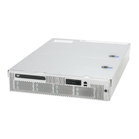
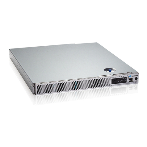
Figure 1: General device view........................................................................................................................................................................16
Figure 2: Front panel components..............................................................................................................................................................17
Figure 3: Front panel LEDs and buttons....................................................................................................................................................17
Figure 4: Rear panel components...............................................................................................................................................................18
Figure 5: IPMI.....................................................................................................................................................................................................20
Figure 6: RJ45....................................................................................................................................................................................................20
Figure 7: Board LEDs.......................................................................................................................................................................................20
Figure 8: System board components........................................................................................................................................................ 22
Figure 9: HDD carrier LED definitions........................................................................................................................................................23
Figure 10: System components...................................................................................................................................................................24
Figure 11: Hot-swappable HDD assembly removal..............................................................................................................................28
Figure 12: Hot-swappable hard disk drive assembly installation...................................................................................................28
Figure 13: Filler panel removal....................................................................................................................................................................29
Figure 14: Hard disk drive installation ......................................................................................................................................................29
Figure 15: Hard disk drive removal.............................................................................................................................................................30
Figure 16: Filler panel removal.....................................................................................................................................................................31
Figure 17: HDD bracket installation.............................................................................................................................................................31
Figure 18: Hard disk drive installation ......................................................................................................................................................32
Figure 19: Hard disk drive removal.............................................................................................................................................................32
Figure 20: Redundant power supply unit removal............................................................................................................................... 33
Figure 21: Redundant power supply unit installation.......................................................................................................................... 33
Figure 22: Access panel removal ...............................................................................................................................................................34
Figure 23: Access panel installation .........................................................................................................................................................34
Figure 24: Air baffle removal....................................................................................................................................................................... 35
Figure 25: Air baffle installation.................................................................................................................................................................36
Figure 26: HDD backplane assembly removal ....................................................................................................................................... 37
Figure 27: HDD backplane removal ........................................................................................................................................................... 37
Figure 28: HDD backplane bracket installation.....................................................................................................................................38
Figure 29: HDD backplane assembly installation.................................................................................................................................38
Figure 30: System fan assembly removal...............................................................................................................................................39
Figure 31: System fan assembly installation .........................................................................................................................................40
Figure 32: Fan cage removal.........................................................................................................................................................................41
Figure 33: Fan cage installation...................................................................................................................................................................41
