Tyros/TRS-MS01
3
Sound Source: AWM
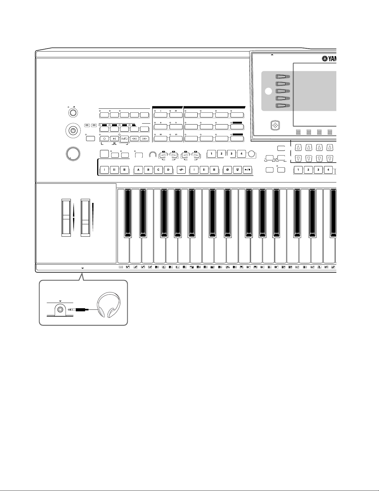
Keyboard:
Keys 61 Keys (C1 ~ C6)
Touch Response Initial Touch/Aftertouch
Polyphony: 128 Notes max
Voices:
Preset Voices 1185 403 voices (Normal: 393 + Mega: 10) + 10 Organ Flutes
voices
+ 480 XG voices + 256 GM2 voices
+ 31 drum kits (XG and Panel: 22 + GM2: 9) + 5 SFX kits
User Voices Maximum number is unlimited; de- Created data can be saved to the USER/FD/HD drive.
(created with Sound pends solely on the capacity of the
Creator function) USER/FD/HD drives. *
Custom Voices Normal Voice: 128 max Maximum number varies according to the type of voice created and
the way in which it was created or edited. For example, if only Live!
GrandPiano voices are saved as Custom voices, up to 94 voices can
be saved.
Drum Voice: 10 max Maximum number varies according to the type of voice created and
the way in which it was created or edited. For example, if only Live!
StandardKit voices are saved as Custom voices, up to 10 voices can
be saved.
Organ Flutes 10 Preset Created data can be saved to USER/FD/HD drive.
Orchestration:
Upper 3 parts RIGHT1, RIGHT2, RIGHT3
Lower 1 parts Includes LEFT HOLD function.
Split Point (Left) F#2 Can be set and memorized.
Split Point (Style) F#2 Can be set and memorized.
Effects:
Reverb 34 Preset + 3 User 1 block; parameters including depth can be edited.
Chorus 26 Preset + 3 User 1 block; parameters including depth can be edited.
DSP Effect 183 Preset + 3 User 1 block for style and song; parameters including depth can be edited.
DSP Effects 183 Preset + 10 User 4 blocks for RIGHT1, 2, 3, and LEFT; parameters in cluding depth
can be edited.
DSP Effect 183 Preset + 10 User 1 block for microphone; parameters including depth can be edited.
DSP Variation (Available) 4 blocks for RIGHT1, 2, 3, and LEFT
Poly/Mono (Available) When set to MONO, the Portamento Time can be set.
Vocal Harmony 60 Preset + 10 User 3 notes polyphony; parameters including balance can be edited.
Microphone Effect Noise Gate x 1, Compressor x 1,
3 Band EQ x 1
Harmony/Echo 17 Preset
Master EQ 5 Preset + 2 User 5 Band
Part EQ 29 parts 2 Band, 29 parts (RIGHT1, RIGHT2, RIGHT3, LEFT, STYLE x 8,
SONG x 16, M.PAD)
Master Compressor 5 Preset + 5 User 3 Band. Type, Threshold, and Gain (3 Band) can be set.
Touch Response 5 Preset
Tempo 5 ~ 500
Transpose -12 ~ 0 ~ 12 Can be set independently for Keyboard, Song, and Master.
Tune 414.8 ~ 440 ~ 466.8Hz Set in 0.2Hz units. A3 is set to 440Hz as default.
Upper Octave -1, 0, +1
Part Octave -2, -1, 0, +1, +2
Pitch Bend Wheel (Available)
Modulation Wheel (Available)
Style:
Preset Styles 300 Assigned to 10 category buttons
User Styles Maximum number is unlimited; de- Created data can be saved to the USER/FD/HD drive.
pends solely on the capacity of the
USER/FD/HD drives. *
Style selection Can be switched between PRESET When USER/DISK is turned ON, the path can be set to
and USER/DISK each of 10 category buttons.
Data Format Style File Format Up to 120 Kbytes per style
Controls INTRO x 3
FILL IN x 4
BREAK x 1
MAIN x 4
ENDING x 3 Includes ritardando (rit.) function
FADE IN/OUT
TAP TEMPO
Fingered Mode Single Finger, Multi Finger, Fingered, On Bass, Full Keyboard, AI
Fingered, AI Full Keyboard
(created with Voice Editor
software)
SPECIFICATIONS (Tyros)