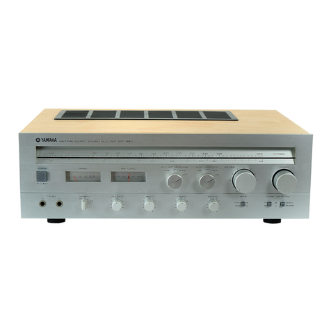
Yamaha R-50 User manual

--
STEREO RECEIVER
R-50
I FRONT PANEL
r--i---T-----=.;=-r--;---lF;;r: l l'!|!rE!GllE.
l* ll "ll * ll I lt:t:iiiiili:iii.iillr.r.rrl
III
I CONTENTS
TOSERVICEPERSONNEL ......1
SPECIFICATIONS. ._....1
REAR PANEL . .. . ......, 2
INTERNALVIEW. ......3
DISASSEMBLYPROCEDURES. ,.. 3
ADJUSTMENTS 4-6
PRINTED CIRCUIT BOARD 7,8
SCHEMATICDIAGRAM ....9
BLOCKDIAGRAM ......9
PARTSLTST. ..10-19
SINCEI8'7 @YAMAHA
NIPPON GAKKI CO., LTD. HAMAMATSU, JAPAN
Printed in Japan 83.3. 2.5k 474 lll@
PDFill PDF Editor with Free Writer and ToolsPDFill PDF Editor with Free Writer and Tools

aR-5()
I TO SERVICE PERSONNEL
(Pr:epared in accordance with UL Standard
12701
Before service of this appliance by you, please
carefully read this service manual.
Please make Leakage-current or Resistance
measurements by suitable meter to determine 1
that exposed parts are acceptably insulated
from the supply circuit before returning the
appliance to the customer.
A PROBE WITH SHIELDED LEAD.
B SEPARATED AND USED AS CLIP WHEN
MEASURING CURRENTS FROM ONE
PART OF APPLIANCE TO ANOTHER.
Confirm that the leakage current is not more
than 0.5mA AC.
I SPECIFICATIONS
Phono O.42mV
Aux,Tape 20mV
Maximum lnput Signal
l kHz 0.01% THD Phono 85mV
Output Level/lmpedance
Rec Out 120mV/1ko
0.015% THD o59v1220a
Phono (lV) 0.015%
LEAKAGE CURRENT MEASUREMENT ClRCUITS
GROUND
Appliance intended for connection to a 1 20 volt power supply.
30dB Ouietinq 75rl 0.8lrv (9.3dBf)
Usable Sonsitivity (DlN)
Mono (S/N 26dB) o.8pv (9.3dBfl (G)(B)(A)
85dB
Mono SOdB (G}(B)(A)
Stereo 76dB (G)(B)(A)
Mono tkHz o.1%
nal to
Mono
Stereo lkHz 0.15%
Harmonic Distortion l4OkHz Devl
Stereo lkHz 0.15% (G)
lkHz 4OdB
30Hz to 15kHz -1.5""
Frequenry Response
20Hz to 100kHz Aux, Tape -3dB
RIAA Equalization Deviation
Phono lo.sdB
Total Harmonic Distortion 513 to 1620kHz (G)(A)(B)
510 to 1620kHz or
Aux, Tape to SP Out 1W8o 0.008%
t ntermodulation Distortion
US & Canadian Models
General Model
European Model
120V AC,60Hz
110 - 120V ACl220 -
240V AC,50/60H2
22OV AC, SOHZ
Bass boost/cut
Treble boost/cut tlOdB (at 50Hz)
tlodB (at 2okHzl
British & Australian Models 240V AC,50Hz
Power Consumption 180W (U)(C)
100w (R)
(Ul ..... U.S.A. model
(C) ..... Canadian model
(A) ..... Australian model
(G) ..... European model
(Bl ..... British model
(Bl ..... General model
Specifications subject to change without notice.
Attenuation -20d8 (at lkHz)
FM 10O%mod lkHz
FM 40kHz mod 500mV/5ko
380mv/5ko (G)
1
Mono 1.6pV (15.3d8f)
stereo 22sV (38.1dBfl
o.8pv (9.3dBfl (G)(B)(A)
852 1.8d8
0.02%THD 17.5W8r}
2.5mYl47k{t 80dB (G)(B)(A)
to (SmV lnput Shorted) 88dB/80dB (G)
Aux, Tape 5.1kO Shorted lkHz 60dB
Tone Control CharactotistiG
Switched 200W max.
Unswitched 200W max.
7-118x4x1
PDFill PDF Editor with Free Writer and ToolsPDFill PDF Editor with Free Writer and Tools

r INTERNAT VIEW
@Removing Top Cover. . . .
@Removing Front Panel . . .
@Removing Bottom Cover
r DISASSEMBLY PR.OCEDURES (Remove parts in order of disassembty as numbered.)
* Replacement of the parts of almost circuit boards in this unit is possible by removing the top and bottom cover.
R-5(,
Q eowen TRANsFoRMER
U.S.A. & Canadian models: cA66400
European model: GA66410
Australian & British models: GA66420
General model: GA66430
O ELEcrRoLYTrc cAP.: 68oopF 46V
@otooe BRTDGE: s4vB2o or RB4O2or 4D4841
@eu roor ANTENNA
@rnorur END PAcK
@ tr tC: ttPC577H E,Fl
@eowen swrrcH
@nowen tc: STK-4873
@unrru ctRcutr BoARD (1)
@uex lc: LA338o
@urcno coNPUTER rc: LC65o2c-604
@rururruc coNTRoLLER tc: LC721o
Cup Screw 4x8 FNM3-3g
Binding Head Tapping
Screw 3xB FCRM3-B[
Binding Head Tapping @ Removing Heat Sink . . . . Binding Head Tapping
Screw 3x8 FCBM3-BQ Screw 3x8 FCM3-BI
g
@
" r-o"r. p
WPipe Fixture
3
Block Heat Sink
Fig. 1Fig.2
PDFill PDF Editor with Free Writer and ToolsPDFill PDF Editor with Free Writer and Tools

I ADJUSTMENTS
<CONFIRMATTON OF AUDIO SECTION>
Before adjustment
Note 1: After the power switch is pushed on, wait for 5 minutes before measuring, to be sure of the most stable operation.
Step Confirmation Test point Rating or standard Adjustment method Rimark
1Power supply voltage
+B-E
_B-E
+20-E
+12-E
+9-E
-9-E
+5.6 - E
FB-E
AB-E
+36V t 5V
-36V tsv
+20v t2v
+12.5V t lV
+9.5V +O.sV
-8.9V t0.5V
+5.6V t0.5V
At FM reception mode'
+12V t 1V
At AM reception mode
less than +1V
At FM reception mode
less than +1 V
At AM reception mode
+12V + lV
Make sure that AC line voltage
comes within
Models AC line voltase
u-c 120V t 10%
G?/i20v L,10%
A,B 240V + 10% No load
2DC offset Speaker terminal
or pin 5 ol 1C112
(L ch) and Pin 12
(R ch) OV t50mV
\l
\-/
<TUNER ADJUSTMENT>
oBefore adjustment
Note 1) After the Power switch is pushed on,wait for 5
minutes before measuring, to be sure of the
most stable operation.
Note 2) Adjust the OSC coil and IFT with a nonferrous
screw driver.
Note 3) Do not forget to keep the bottom cover on.
1. FM TUNER SECTION
oUse 200H2 to lskHz bandpass filter to measure the
REC OUT.
.On step 1 and 2 connect the auxiliary center meter
(J|0OO36 or similar) in series with the resistor 1OkO
between TPI (S OUT) and TP2 (NVcc).
Auxiliary center meter
o Measu ring inslruments abbreviation
FM SG
SSG
AM SG
OSC
DIST. M
FC
ACVM
FM signal generator
Stereo signal generator
AM signal generator
Oscilloscope
Distortion meter
Frequency counter
AC volt meter
oSet the switches to the following positions.
INPUT .... TUNER
BandSelect .. FM
TUNING/MODE ... AUTO
VOLUME . . Min
4
Step Adiustment item Connection
terminal tnstrument required Adiustment
locations Adiustment method Rating or
standard Bemarks
1Detuned noise
confirmation T101
(ST DIST} Adjust noise level to
maximum at detuned
point.
2Discriminator
balance adjust-
ment
TPl -TP2
(S out)(NVcc) Auxiliary center
meter T102
(DISCRI
CENTER}
Adjust so that the
pointer of the auxil-
iary center meter points
to 0 at detuned point.
3station center set
confirmation 300s} FM
ANT
TP1 -TP2
(S out) (NVcc)
FM SG
[gguH, t tttt, I
lzoosrr (75.2dBr) |
IMONO lkHz I
[roox uoo ]
Auxiliary center
meter
TUNING SW
+UP or DOWI Confirm that the auxil-
iary center meter
deflects to 0 at tuned
the signal of FM SG
4Monaural distor-
tion adiustment 300r} FM
ANT
REC OUT
(TP7, TP8}
FM SG
[98MHz t 1t<Hz I
lzoaep l75.2dBtl I
I monaural 1 OOHz orl
L+oon' 1oo% MoD_.j
DIST. M. OSC
BPF
vc101
(MONO DIST) Reduce distortion to
minimum Less than
-64d8 Confirm that
all signal O
indicators
lisht
PDFill PDF Editor with Free Writer and ToolsPDFill PDF Editor with Free Writer and Tools

Adiustment
locations
VB102
(vco)
Stereo indica'
tor
Adiustment method Rating or
standard Bemarks
Step Adiustment item Connection
terminal tnstrument required O Connect resistor
2.2Mo between TPs
(i9M) and 1p6 (+12)
and force the set in
stereo mode.
@ Adiust so that VCo
frequency is at lgkHz
19kHz I
lOHz Confirm that
stereo indi-
cator lights
up.
After adlust-
ing, remove
the FC and
2.2MA
resistor.
5VCO adiustment 300s, FM
ANT
TPs -TP6
11gtvl) (+12)
TP3 - TP4
(19kHz) (G)
FM SG
fgSMHzttt<Hz I
I zoasp (7s.2dBf) I
I Unmodulated -l
hesistor 2.2Mo
FC
T101
(ST DIST) Less than
-48dB
G model
only Less
than -35dB
Not adiust
T101 , when it
is within
specifications.
6Stereo distortion
confirmation 300s, FM
ANT
REC OUT
(TP7, TP8)
FM SG, SSG
'98MHz t lkHz I
70dBp (75.2d8f) I
STEREO L, R I
1kHz, 100% MOD.I
Dtsr- M, OSC
BPF Confirm that the leak-
age level of the
opposite channel is
minimum
Less than
26dB
7Separation confir-
mation 300s) FM
ANT
REC OUT
(TP7. TP8)
FM SG, SSG
lsst\rHi f ttl'{z I
I zoaer, (7s.2dBf) |
I STEBEO L or R I
I rtnz, toox rrltoo-l
bsc, acvNlt, ePr
3000 FM
ANT
REC OUT
(TP7, TP8)
FM SG. SSG
lg8MHz t 1t<Hz I
I zoaep (75.2d8f) I
Lprlor 9% MoD -l
osc
ni.annnant RPF
VRl01
(PILOT
CANCEL}
Observe waveform on
the OSC and adjust so
that carrier leakage
le\rel reduced to
minlmum
More than
34dB
IPilot cancel
adlustment
Confirm that the
auxiliary center meter
points to 0 at tuned the
signal of FM SG
lf it is not
points to 0,
start allover
from step 2.
IDiscriminator
balance confirma'
tion .
Tfi -TP2
(S out)(NVcc)
300s, FM
ANT
Auxiliary cente meter
FM SG
l-98MHz i lkHz I
l-roac, t-15-2dBfll VR103
(FM FINE) By shorting TEST
terminals, the counter
shifts by one digit, then
adiust so that the
lowest effective digit
comes to I or 0.
r-This figure
I -8O.O
g8.0MHz-1*79 E
When shifting
After adiust-
ing, open the
TEST termi-
nals.
10 lf offset adiust'
ment 300a FM
ANT
TEST termi-
nals
(K4, T6)
FM SG
[98MHztlkHz I
[zoaeu (75.2d8f) -]
Short
TUNING SW
+UP or
DOWN
Confirm that auto
search recePtion is
possible with the tun'
ing button.
Confirm
that muting
is performed
at auto recep-
tion.
11 Auto search
reception confir-
mation
3000 FM
ANT FM SG
[9BMHz t t tHz
lzoaar l25.2dBtl
I ruoNo t tgz
Irooga moo
J
J
2. AM TUNER SECTION
oConnect the AM dummy antenna for adiustment' oWhen once the test terminals are shorted in adjusting
FfU, tt',. frequency of 630kHz, 1440kHz' -and 1080
tH, it memo;ied at each AM preset position 1' 2 and 3'
J
Adlustmenl
locations
PRESET
P1
P2
P3
Adiustment maftod Rating.or
$andard Remarks
Step Adjustment item Connection
terminal lnstrument required
Confirm the maximum
sensitivitY less than
55dB,r
1SensitivitY confir'
mation AM ANT
BEC OUT
(TP7, TP8) DST. M
ACVM
AM dummY antenna
AM SG
l-1O8OkHz t 0.1 kHzl
fsoaar ]PRESET
P3
Signal O
Confirm that all signal
O indicators light. Confirm that
all signal O
indicators
goes out at
detuned
point.
2Sign'al O indica'
tor confirmation AM ANT
TUNING SW
+UP or
DOWN
Confirm that auto
search recePtion is
possible with the
tunning button.
3Auto search
rqception confir'
mation
AM ANT AM dummY antenna
AM SG
[1 oSokHz i 0.1 kHz I
[ooaar ]
PDFill PDF Editor with Free Writer and ToolsPDFill PDF Editor with Free Writer and Tools

3. DIGITAL CONTROL SECTION
.TEST POINT
6
Step Adiu3tmont itom Connection
terminal !nstrument required Adjustment
locations Adiustmont method Rating ot
standard Remarks
IPreset memory
confirmation 3000 FM
ANT
AM ANT
FM SG
[98MHz i lkHz I
lzoaep 7s.2dBtl I
luoruo trxz I
Lroox rvroo I
AM dummy antenna
AM SG
[ro8orxz io.lkHzl
lsodep I
L+ooxz,30% MoD l
FM/AM SW
TUNIT{G SW
MEMOBY SW
PHESET SW
O Memoring the PRE-
SET Pl at FM SG
frequency.
@ Memoring the PRE-
SET P2 at AM SG
frequency.
@ Confirm that the fre-
quency memorized is
recalled.
O Press the FM button and
tuned the 98MHz with
AUTO seach
J
Press the Memory
button.
.f
The Memory indicator
lights about 3 seconds
J
Press the PRESET Pl
during the Memory
indicator lights.
.l.
The PRESET LED of
Pl lights.
@ Press the AM button and
tuned the 1080kHz with
AUTO seach.
+
Press the Memory button
.1.
The Memory indicator
lights and the PBESET
LED of Pl flash6s.
T
PrCSS thE PRESET P2
.1.
The Memory indicator
goes out and the PRE-
SET LED of P2 lights.
2Last channel
memory confir-
mation
POWER SW O Press the PRESET Pl
@ Turn the power
switch off.
@ After about 5
seconds, turn the power
switch on.
@ Confirm that the
PRESET Fl memorized
is recalled.
@ tnepRg-
SETof Pl dbe:
not lights
lel ffifll
!h ,[3. --srDsr
(-) ffira
n Q_-r,",0.-.., ,ffi]]
tl qssB/ffi _ 8Hffl;''"
w
E C$3 l-rcr.4 1 R2o4
t/r ==fu
l-#',",,,1118 ltsJJD-m
iffii''i vEi6zr^'* mi
-&-&- vco ','6tr#
g*3
*[H " "Q"
I ,"'os I r;l
PDFill PDF Editor with Free Writer and ToolsPDFill PDF Editor with Free Writer and Tools

From MAIN C.BOARO('/6)
I
BOAR.D (Pomern side)
I PRINTED CIRCUIT
oKey circuit board
oMain circuit board 1216 - 6/6)
To MAIN C.BOARD(116,
To MAIN C"8OAR0{l/6)
.7a F.an MAIN C.BOARD(l/6)
Main C. Board
(5/61
To MAIN C
Main C. Board
(6/6)
From
From MAIN C.BOAR0(l/6)
From i/tAlN C. BOAfrO t ll5)
TUN_UI|_G- TUNING
/MODEMEMORY FMAM DOWN
To MAIN C.$0ARS(llS)
MA
Tq MAIN C.B0ARD(l/61
From i,lAlN C. BOARD(116)
Frorn MAIN C.BOARD
il/6)
3
c'
g
L.'
i", r,
-o
Jc
3c
o.3
-. !r'
vc,
<tE
i,
Eu
8a
IL {
0q
)
Main C. Board
14l6l
Main C. Board
l2l6l
SPEAKERS
AB
oFFI OFF
ON- ON 7
SPEAKERS
Fr*m MAIN C.B0ARD{l16)
To MAIN C.B0ARDt316l
PDFill PDF Editor with Free Writer and ToolsPDFill PDF Editor with Free Writer and Tools

R-5(,
PARTS LIST
r ELECTRICAL PAR.TS
TWARNING
UL Standard 1270 requires'that components marked A be
replaced with parts having specifications equal to those
originally installed.
. Carbon resistors of this receiver are YrW.
There is no discription about them in this parts list.
Use the "Part No." HJ35OOOOoT equivalent.
Ref.
No. Part No. Description \sff€ Remarks Common
Model Markets
,,t L#. . ':.'j.--'.1
lT:*::T--
ffi
lfirt:?y,1"!{€]*i:*ll
ffi
{i:i::ir$a:ii:llia{i!Mi
ar:tir!:ifir*:!.li:i 3
?f&f$:!".i1xt]}i*
i,r*l;iri$;*i:*.
8n'{ffi{fi*tf
u:k. r:b r-:l ;. - '
:ta.*&;:{:lt :a:tii,a
fll'l1t:riy35*xi;iri
I,-'.'r ".:;
ffii
l .i-" 'i;1
msps$$s
[&tr*sE
Kt]rix;'*i
q*1!-tffi**
iill*]ri:|l;:;:ii:l
i*{***rl
ff**:]ix
re ;
"1":';*{{.*'..1: l
rffiffi
' "lt- '.
FG 4r3 !90 Ceramic Cao 39pF 50v e. 2Ic249,250
FG 4170 47oF sOV c221,222
FG 421 iOO IOOpF 5OV c 199.200 G
FG 4 22120 22Oot 50v c1 91,1 92 G
FG I4 22 20 22OpF 50v cl49.190.241 .242
FG 423 :30 33OoF sOV c1 93-' 1 96 G
G425 60 56OpF 50v c217.214
FG :4 31 rOO 1 OOOoF 50v c108,168
G731 i80 18O0oF sOV c239,240,251,252
FG I4 34 70 47OOoF 50v c287 -290 G
G44i4 oo o.o1 ,,F 50v cr 05,r 06,r 57,r 67,1 69,r 71,1 84,
20s 2to 263
FG i4414 o0 o.o1!F 50v c219,24O G
G44t 420 o.o22,,F 50V c281 -286 G
FG i44144 70 o.o47 uF sOV c237,234,259-262
G t44 42i20 o.o22pF sOV c215.216.264.265
FH 241 ioo o.o!rF soov c1 86
120 22pF sOV cl76.177
I19:21 ioo 1 OOpF 50v cro9,r 10
:G 21i31ioo IOOOpF sOV c143,1 52,1 60
FG 121i24i70 47OpF 50v c1 53
FG 21 134:70 47OOpF 5OV cl14,117,114
22i 41 iOO O.Ol rF 25V c I 02- 1 04.1 3 I.1 34- 1 37.144.
la5 r6t r69 r8! 2rt
I22i41 iOO o.olrF 25V c1 55 G
I22 42120 o.o22uF 25V R,U,A,C,B
I22 42i20 o.o22pF 25V c127 ,134,140,245,246
S25 26i80 Semi Conductive Ceramic Cap. 68OpF 50v sAIc126
U35 70 Mica Cap. 27pF SOOV v.{ ,1 lc170
FZ 00i35 80 Electrolytic Cap 4TOOOIF 5.5v ,:c1 73
zo0 390 Ceramic Cap. 0.1!F 25Y E7I c233,234
FZ OO: 39 i 40 Electrolytic Cap 68OO/F 50v tfc266,267
uA i2s 241 70 Mylar Cap. 47OpF sOV c1 15,1 16 A,G,B
UA 25 26i80 68OpF 50v R.U,C
UA 25 26 80 68OpF 50v c123 R,U,A,C,B
UA 25i3 oo IOOOpF sOV G
UA 25 3 oo IOOOpF sOV c121,122
UA 2513 50 lsOOpF sOV c112
UA 25 4 oo o.o14F sOV c1 29,1 30
UA 25i4 50 o.o1srF sOV c1 50
UA 25 460 o.016,,F 50V c203,204
UA 25i 480 o.ol8!F 5ov c223-226
UA 251 44i 70 o.o47 pF sOV c151.162
UA 25i45 60 0.o56!F 50V c201,202
UW 91 i 73:30 Electrolytic Cap 33!F 6.3V ,fc279
UW 91 i74i70 47pF 6.3V c141,142
UW 91 i81 !OO IOOIF 6.3V c1 58,1 97,1 98
x New Parts (trffiEBe)
ro
PDFill PDF Editor with Free Writer and Tools
Ref.
No. Part No Description S fi ARemarks Common
Model Markets
UW 91 82t20 Electrolytic Cap. 22OuF 6.3Y ,fcI1 1
JW i81 i84 i70 47OpF 6.3Y c174,179
UW a2i74170 il 47pF 1OV c27A
Ui 93:82 20 22OpF 16V c183.207.220
UW 93i71:OO 10uF 16V c 1 01,1 07,1 1 3,1 24.1 39,1 48.
156,1A5.172
uwi93i73t30 33pF 16V c141.166.140,275
UW 93 74 70 47pF 16V c182
UW 94 74i70 47 pF 25V c276
UW 94 93 30 33OOaF 25V c268
UWi85 72 20 22uF 35V c243,244
UW 86152120 o.22uF sOV c1a5,213
UW 96 54 70 o.47 uF 50V c1 48,1 63,1 64,1 75
UW 96 61 tOO 1 uF 5OV c1 1 9,120,1 25,1 2a,1 32,1 49,1 47,
1 8A,212,2A9 .27 1 ,27 4.27 7
UW 96i62t20 2.2uF 50V c1 33
UW 96 63 30 3.3!F sOV cl 47 .17 A
UW 96t64t70 4.7 pF sOV c205 .206,21 1 ,231 ,232,235 ,
236
UW 96 71 oo lOrF sOV c208227 -230,256,
272.273,291
UW 96 i72 20 22pF sOV c270.254
UW 96i74170 47 pF sOV c255.257.258
UW 86 81 oo l.OOrF 5OV c253
FY oo :01 i90 Trimrher Cap 5P vcl 0r
3D 90 io3 r40 Output Coil 1.5 pH 7rl1,vl=1w Ll 07,1 08
3E 30 io4 iso lnductor lmH .t2yrr- L',t 04.105
3E 30 i05 roo 12 pH Lt 03,1 06
3E :30:O5 10 12O pH L1 01
3E i90 i06 90 8.2mH Ll 02
GE 1O r02 i80 FM Discriminator Coil cE1 0028 FMi.l 7rt)a1)v I102
GE 10 06i50 FM IFT GE1 0065 F M IFT T1 01
GE 20 o4 30 Anti-birdie Filter 1 1 4kqz 7>ur<-71-71rW -T1 03
GG iOO iO4 i20 AM Ceramic Discriminator 3DA4sOA AM{s' i ,yri I 7, ulF1 04
iG ioo io6 i2o FM Ceramic Filter sFEt U. /
3GHY-Z FM.zr: ,2r7 I )v9 _)F101 ,102 J
3G iOO io6 30 MMH-Z R-U.A.C,B
:c ioo io6 i60 {M Ceramic Filter SFU-45O89 AM,ts7i ,27 I )V? _CF1 03
HF i85i42 20 Carbon Resistor 22a 1 /6W ,,- 'dF.r#,fr, R127,128
HF i85i5 oo 1OOO nRl 35,1 60,1 I 1
HF i85i5 20 12OA il R277,274
HF i85i5 50 il '1509l il R1 03,
HF i85i5 50 l5OO uR271.272 R,U,A,C,B
HF ;85i61 i50 1.skQ il G
HF:85i52i20 220A R1 08.1 76.258,36 t
HF i85:53i30 330() R104,321,322
HF ! 85r 54i 70 47OQ il R290,307,308
HF i85i55:60 560C) R265 - 268 R,U,A,C,B
HF ;85i 62i 20 il 2.2ka nG
HF i 85i61 iOO lkQ nR102j41,179,250,370
HF l85i6tr20 1.2kO DR1 39,252
HF i85i61i20 1.2k4 il R273,274 G
N New Parts (trffi*Efi)
A
A
tl
PDFill PDF Editor with Free Writer and Tools
a
t
x
*
x
x
*
*
\-, x
*
x
n-5(,
Ref.
No. Part No. Description l[ fr 4Remarks Common
Model Markets
HF i85 61 50 Carbon Resistor 1.5ka 1/6W n-#>*,fri. R1 71
HF 85 61 80 1.8k4 il R297.298
HF 85 62 20 2.2kf) ,, R244,247,339,340
HF 85 63 30 3.3kO nil R167,175,235,255,257
HF 85 63 90 3.9kO il R31 7-320
HF 85 64 70 4.7 ko il nR1 01,1 33,1 34,1 56,1 77,241
2A1-282
HF 85 66 80 6.8kA il R109,1 1 0,1 78
HF 85: 68 20 8.2ko il Rl 81
HF i85 71 oo 10ko il R1 23,1 24,1 62,1 63.1 69,1 92.202.205.21 5
21 6,236,237.242.256303.304.359.368
HF 85 7r i50 lsko il R1 1 r,203
HF 85 72 20 22ka il R1 10,21 3,21 1,224,233,24 6
276,249
HF 85 72 70 27k9- il R164,249,311 ,312
HF 85 73 30 33ko il Rl42,230,243
HF 85 73 90 39ko il R246,366
HF 85174 70 47kA nR157 ,229,234,305,306
HF 85 75 60 56ko nR259,260,279,280
HF 85 76 80 68kA il R1 80
HF 85 7A 20 82kO il R369,292
HF 85 81 oo IOOkA il fr 25.124,15t,742,t54,2@,2 1 A - 224,239,
2 4 0,2 6 1.2 8 5,2 86, 3 2 3, 32 4.347 )348.3e5
HF 85 81 80 l80kO il R360
HF 85 a2 20 22OkA il Rl 38.1 49.1 52.1 53,226,234
HF 85 83 30 33OkO nR227 .245,24a,29 1,3 1 3,3 1 4
HF 85 a4 70 47OkO il R1 59.1 90.206.295.367
HF 85 88 20 82OkO il R309,31 0
HF 85 91 iOO 'lMO il R197 .251 .261-264.31 5,31 6
HG 30 92 20 2.2MA RDsOS R373 U,C
HL 71 34 70 Metal oxide Film Resistot 4.7 a 1P *fl8 frt R345.346.349.350
HL 7 51 50 150fi lP R355
HL 752 20 220a 1P R371,372
HL 72 45 60 55() 2P R363,364
HL 33 53 90 3900 3P R356
HU 57 81 o0 Metal Film Resistor 100ko fElfrtrff-flt R217
HV 35 42 2A Flame Proof Carbon Resistor 22a RDF2SSF 4*'IYh - t r*,ilE R332
HV 35 51 o0 lOOo nR331
HV 35i 48: 20 82a il R354
HZ o0i 29i 20 Metal Plate Resistor o.47 a 3P errfi*fr R337,338
HT 37: OOr 5C Semi Variable Resistor 85ka +Et*Efrt vRl 03 |
,, Ilntet"hangeable
HT 5osi 7c BSka
HT 37 ooi 2c Bl oka vR1 02 l
,, I lnterchangeable
HT 57! 05 8C B1 okQ
HT 37i OO 3C B1 00kO VR1 O1
HS 418 4C VR unit VRr:vl' VR1 04
HS 418 5( Variable Resistor EI *. iE fr IT VR1 05
IW 39 41 oo Fuse Resistor 1Oo l/4W Er-/8,fr, FR1 O1
Ao9 70 oo Transistor 2SA97O (GR,BL) lr>r7, TRT16
iA o9 99 'lo 2SA999 (E,F) TRI 1 0, r 1 3,1 20,1 21,124.127,129,
1 30-l 32,1 37 - I 40,r 44,! 55,1 56 lnter-
changeable
A127 oo 2SA1I27(R,S,T)
iA 12 62 oo 2SA1262(O.Y,G) TR1 49 r
,, I lnterchangeable
Bo8 34 oo 258834
x New Parts (#AI8E)
A
t2
PDFill PDF Editor with Free Writer and Tools

R-no
t
)t
I
t
I
R€f.
No. Psrt No. Description $ & 4R6marks Common
Model Markots
ic 19i 23i O( Transistor 2SC1 923 l.ry^, TRl11
ic 20; 88! o( t, 2SC2088(BL,V) TRI 47.1 48 )
,, I lnterchanoeable
ic 22 tro: o( 2SC2240(GR,BL)
ic 23 20i 1,t 2SC2320(E,R lnEr-
cttangsbh
ic 261 34i O( 2SC2634(R,S,T)
ic 28: 78: O( 2SC2A7A TRl45,146 )
,, flnterchanoeable
iD 13: 02: O( il 2SD13O2(R,S)
iD 06: 55: O( t, 2SD655 (D,E,R TRl03,1@,109
u
lnterchangeable
iD to: 12: (x 2SD1012(G.Hl
iD 13! 02i O( il 2SD1302(R.S)
iD ()4: ooi 2( il 25D400(F) TRI 52,1 53
iD ogt 72: O0 u2SD972 il TRl57 'l
,, I lnterchangeable
iD ooi 36i 0O 2SD635
Foo:oo 40 Diode lSl 555 ,IlJ FD102.103
F00:oo 40 il 1 Sl 555 DDtor.tg.t6-rrl,rl3-122, \ _
t2a-t2G.!3O,r32,t33 | lnter-
, I "hangeable
F :OO 106 70 t, 152473 tt
F iOO I i4O Zener Diode RD3.OEB2 Y z*-r.l rl- FDl05,1 12
Fi@ 33 20 t, HZgC-3 o128,129
F ioo 16 70 RD6.8EB2 D131
F loo 44 30 ,t HZ12C2 D127
H :OO o8 o Dictdo Bridgo lB4B4t ,1zl-frt)vY D134
H iOO iO8 70 il 4D49,1 otit
i,*o"n"nn""o,"
H iOO o40 il RB4O2(LFD) ,t
H :OO o i90 s4vB20
iG oo 12.70 tc TC/IO66BP crcl10 )
,, I lnterchanoeable
ts o8 92 iOO ,t LCrtOo6B
iG oo 13 !gO ,t NJM4558DV t, rc103
iG i02 92i20 t43380 t, tc104
Gi03 i45 ioo ,, rPC577H(E,R tc 101,102
Gio4 11 ioo ,t M544591 tc105
G lo4 isl ioo 1C7210 ,t tc107
G !O8 ior i00 ,, LC781 5 ,t rcl 09
G io8 :s3 ioo t, LC6502C-604 rc106
c io8 i89 ioo ,t sTK4873 cl12
G :O9 i21 ioo il M521 9L tcl11
G :O8 i52 iOO lt AN6557 t rc108 )
,, l lnterchangBable
G :O8 :29 i(x) t, NJM2O43SD
KA &o9 40 Slide Switch ss&o22 7r.1F,(.lv' swl06 R
KA 80 2Ai2A Push Switch 2circuit2poim /'y'2t71v, sw107
KA 80 37 40 nswl08
KA 90 29 30 Switch ,rl^1.t7 swl01 -105
(B ioo !o3 iso Fuso T2.OA 250V Ea/, F1 01 R
(B ioo 16 EO T1.6A 250V t, A,G,B
(B iOO 10 30 ,t 2.OA 250V tt t, U,C
KC iOO ioo Relay DCl2V UvRYlOl R,A,G,B
KC aOO 1a bo il ,, It ,, U,C
LB 20 22igo Pin Jack 2? C>'>+"t2 PJl 01,103
* New Parts (f,rf,te)
r3
PDFill PDF Editor with Free Writer and Tools

a'-
x
R-50
Ref.
No. Part No. Description il fr 4Remarks Common
Model Markets
B40 10 30 Pin Jack 4P e>Y+y? PJ102 K-100o
LB 30 17 50 Headphone Jack Gray ^y Fri>ra,'y, JK1 O1 A-500 B,U"A,G,C,B
LB 30 17 60 Black R,G
PA iOO o7 5C Front End Pack FE529U1 2 7a>la2F.ly2 PKl O1
ou i ooi 39i o( OuarE Crystal Unit 32kHz 7kEfrt+
TA ooi 39.9( Antenna Terminal 5P 7>it*+& R,U,A,C
LA ooi 40i o( 5P G,B
LA ooi 42 5( Speaker Terminal 7c-h-t - a.ttt R,A,B
LA ooi 43i 3( ,t U,G,C
Aooi 21 1( Wrapping Terminal P=5 2P i-Type i 8.7'y Erl**& U,G,C
LA ool 20i o( P=7.5 2P i-Type
LA ooi 23i 2( P=7.5 3P i-Type R,U,A,C,B
LA oo: 25i 7c Pi7.5(0) 3P i-Type G
LB 20; 13i 9C 2.5 Pitch Base Pin TE82P.SHF 2.5 t vA<-78>
B20 t8:80 Fuse Holder Pin PC-FH1 E a- /,b)vr - C,
B92i 10140 Connector Plug 4P(i-Type) a*2r-rr,
B92 10i 50 5P(i-Type)
B92 10i60 6P1i-Type)
B92 10:80 8P(i-Type)
B92 ro! 90 9P(i-Type)
NA o8 10!80 AM Coil Pack AMf-fw,t.y2
AA 61 70i r0 Sealed Plate 40x30 tv li ffi
AA 61 69i 90 60x30
BA 08! 40i o0 Radiatol ft ll #K-1000
BA 08 57i 50 Radiation Block fr.*ra'v) R-30
BB o6i 83:70 Ground Plate 77tft E
CB o6 88! 80 Plastic Rivet ,77rv2l<y I
Binding Head Tapprng Screw 3x8 FCM3-B, ^.1 2F9vEr/*2
3x14 FCM3-8,
cB io6 !92 50 Bindinq Tie BK-1 12!ray2?1
)* New Parts (rrESB)
t4
PDFill PDF Editor with Free Writer and Tools

R*5O
I MECHANISTvf PAR.TS (All-over)
X
x
x
X
x
x
X
X
x
iX
X
X
X
x
X
Y
X
N
*
x
x
X
X
x
t6
tll)b l:y l
>-r-rir>
3Il# t >
ArZr,vrtt<t I
,awr'y27-/
PB i06i28i +-dt- p:: z l
3x6 ZMC2-Y '<1rF4.*,
Itr l.7>^
aE,liltl*
f-ti.rtl.yzt-
CB'tOll27l +*!*+f
LA iooi29:5 Ez-/rhrVr-
ACTrlv.yl
6 A250V 2 m
7.5A250v 2.5m
2.5A250V 2 m
6 A300/500V 2 m
l0A l25V 1.98m
l0Al25v 2m
NAiO8il6i
NA i08i16i
NA:O8r16i60
NAiOS:16i70
NAi08i16i80
NA i08i16i90 y2t71y
au7>t-hrr-
T2A 25()V
AA i61i64iOO
AA i61 i64i10
AA i61i64:20
B-EX>-t
A
A
A
A
IA
A
,/\
A
/\
/1\
/\
A
x New Parts (filtf,)
PDFill PDF Editor with Free Writer and Tools

a.A
R-5(,
Unii Bose
f MECHANI Sm PARTS ( Keyboord Unit)
x
L.:
Ix
[ix
itl
r
k-
F' x
Ref.
No. Part No Description IeRemarks Common
Model Markets
1AX i60ioo 40 Spring SU53O4WPB zrt)>,
2cB i61 i73 i2O Button Silver #,POWEB
il cB i51 i73 i30 t, Black t, t,
3nx ioo iooizo Spring, Hold t 1.6 zt *ti
4CB i61 i75 i00 Button Blow Silver ,frr>aaO PRESET
lt cB i61 i75 i30 ,t Black It u
5AX i60 ioo i50 Spring, Button SUS3O4CSPH ,!f9>/{rt INPUT
6Ax i6O oo i60 unPRESET
7cB i61 73 i80 Button Silver d{ ITUNER
,t cB i61 74i2O t, Black ,t It
ICB i61 73 i90 tt Silver vtDEo/AUX
il CB i61 74i30 ,t Black nIt
ICB !61 74iOO il Silver PHONO
t, CB i6,I 440 ,t Black ,t t,
10 cB i61 74 ot, Silver TAPE MONITOR
il cB:61 74 50 t, Black ,t t,
11 cB i61 i73 i40 It Silver PRESET
il cB i61 73 50 t, Black t,
l2 EA :O2 i60:66 Pan Head Tapping Screw M2.6x6 zMC2-Y *<9'y C>, *>
x New Farts (trtlilfi)
I8
PDFill PDF Editor with Free Writer and Tools
r
IELECTRICAL PARTS
\z-/
!
Ix
X
x
x
\2,
X
X
R-50
Ref.
No. Part No. Doscription l0 fi eRemarks CommOn
Model Markets
taa :Qn:rOrEn Switch 9rl71v)f
JWt86i62 20 Electrolytic Cap ?,2yF SOY ,cl ,2
iF';io0i45 4LED SLR-34URC3H LEDtRed)
iF iooi42 80 lt SLR-55MC3H t, (Greenl A-500
iF ooi42 70 t, SLR-s5URC3H t, (Red) n
iF ooi45 50 tt SLR-34MC3H il (Green)
iF ooioo 40 Diode ts1555 !1*FD1 -5
iA i09i37 oo Transistor 2SA937 lr>*zt TR1 _3
iG o4i94 oo tc L81274 tc 'l lnterchangeable
il M54527P It J ReplacedbylC:181274
ix 60i14 70 ,t M54560P il
iF iOOi44 10 Frequency Display LC-205MK(N) Etf,*frt! Silver
iF ioor44i20 t, LC-2O5MK(B) tt Black
x New Parts (|trf,ile)
t9
PDFill PDF Editor with Free Writer and Tools
Other manuals for R-50
2
Table of contents
Other Yamaha Stereo Receiver manuals

Yamaha
Yamaha HTR-4071 User manual

Yamaha
Yamaha RX-V3085 User manual

Yamaha
Yamaha RX-V767 User manual

Yamaha
Yamaha HTR5540OM User manual

Yamaha
Yamaha RX-A2080BL User manual

Yamaha
Yamaha AVANTAGE RX-A2A User manual

Yamaha
Yamaha RX-950 User manual

Yamaha
Yamaha RX-930 User manual

Yamaha
Yamaha HTR-5630RDS User manual

Yamaha
Yamaha RX-397 User manual

Yamaha
Yamaha RX-V10 User manual

Yamaha
Yamaha RX-300U User manual

Yamaha
Yamaha RX V565 User manual

Yamaha
Yamaha RX-V890 User manual

Yamaha
Yamaha R-N301 User manual

Yamaha
Yamaha CX-A5000 Instruction manual

Yamaha
Yamaha RXA3070BL User manual

Yamaha
Yamaha RX-V581 User manual

Yamaha
Yamaha R-7 User manual

Yamaha
Yamaha RX-V670 User manual