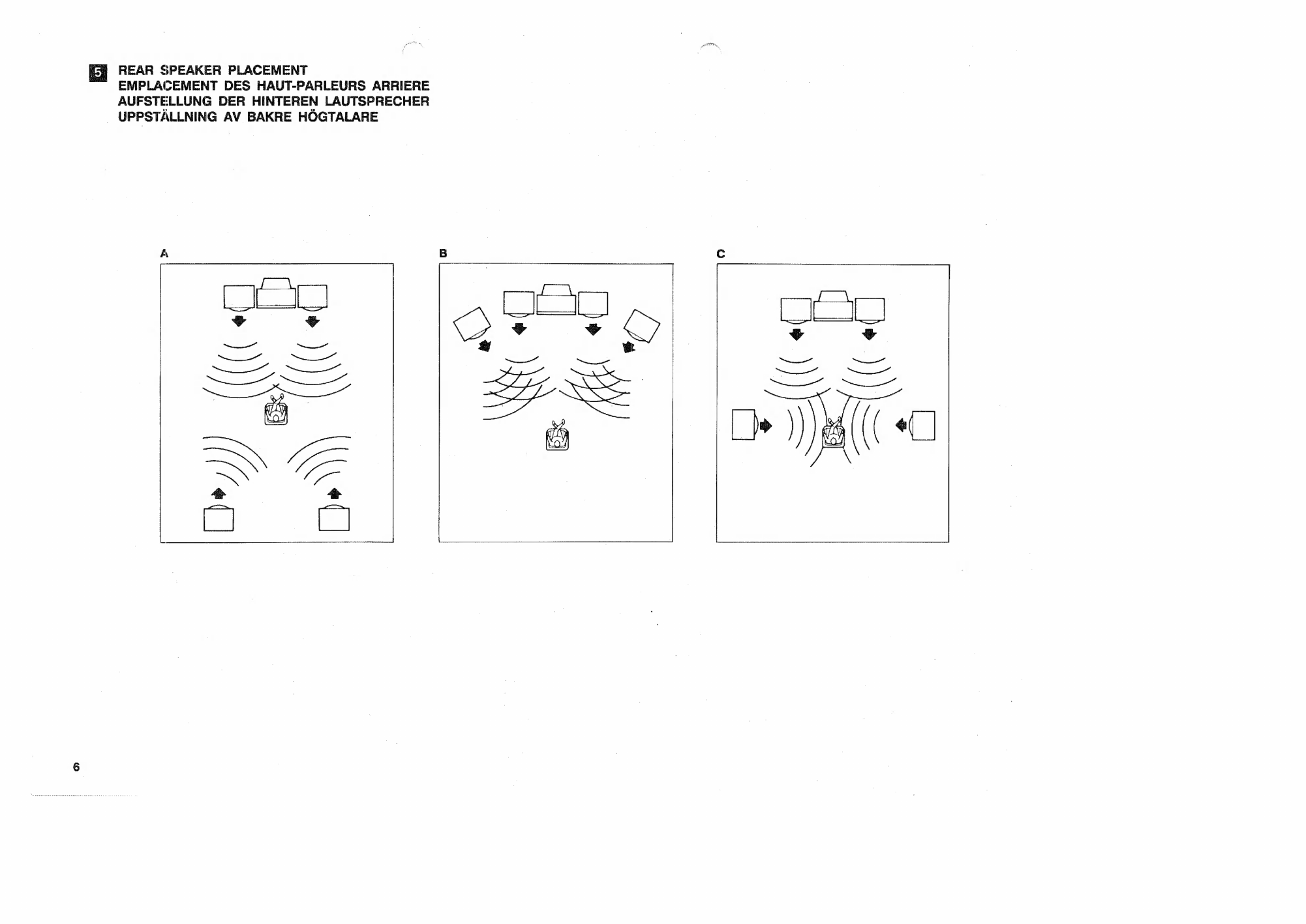
Yamaha RX-930 User manual

EMPLOI
MODED'
OWNER'S
MANUAL
BEDIENUNGSANLEITUNG
BRUKSANVISNING

SUPPLIED
ACCESSORIES
EE
ACCESSOIRES
FOURNIS
|
MITGELIEFERTE
ZUBEHÖRTEILE
MEDFÓLJANDE
TILLBEHÓR
e
Remote
Control
Transmitter
@
Batteries
e
Emetteur
detélécommande
—
ePiles
e
Fernbedienungsgeber
€
Batterien
e
Fjárrkontrollsándare
ə
Batterier
(υ.5.Α.,
Canada,
Australia
and
General
models)
(Modéles
pour
les
Etats-Unis,
le
Canada,
l'Australie
et
Général)
(USA-,
Kanada-,
Australien-
und
allgemeines
Modell)
(Amerikansk,
kanadensisk
och
australisk
modell)
`
(Europe
and
U.K.
models)
(Modèles
pour
l'Europe,
et
le
Royaume-Uni)
(Europa-
und
GroBbritannien-Modell)
(Europeisk
och
brittisk
modell)
@
AM
Loop
Antenna
e
Remote
Control
Cable
(6-pin.
cassette
deck)
e
Antenne
AM
à
boucle
e
MW-Rahmenantenne
€
AM
ramantann
e
Fernbedienungskabel
(6-polig,
Kassettendeck)
ø
Fjårrkontrollkabel
(6-polig,
kassettdåck)
e
indoor
FM
Antenna
e
Antenne
FM
intérieure
e
UKW-Innenantenne
(U.S.A.,
Canada,
Australia,
U.K.
and
General
models)
e
FM
inomhusantenn
(Modéles
pour
les
Etats-Unis,
le
Canada,
l'Australie,
le
Royaume-Uni
et
général)
(USA-,
Kanada-,
Australien-,
GroBbritannien-
und
allgemeines
Modell)
(
Amerikansk,
kanadensisk,
australisk
och
brittisk
modell)
e
Remote
Control
Cable
(mini-plug,
turntable)
è
Câble
de
télécommande
(mini-prise,
platinetournedisque)
€
Fernbedienungskabel
(Ministecker,
Plattenspieler)
e
Fjárrkontrollkabel
(miniplugg,
skivspelare)
е
Сабе
de
télécommande
(6
broches,
platine
à
cassette)
(Europe
model)
(Modèle
pour
l'Europe)
(Europa-Modell)
(Europeisk
modell)

FRONT
PANEL
PANNEAU
AVANT
FRONTPLATTE
FRAMSIDA
PIB
sil
BBE
Bae
anli]
CEET
do
ERE
å
I
ær]
REC
DUT
`
тишке
PHONES
SPEAKERS
WC
NENUNDE
ως
ИЄА.
model)
@
Display
window
Fenétre
d'affichage
PRESET
STATION
E
SIGNAL
QUALITY
Cd
ee
Display
ami
T
IE
a
z
[up
TRE
Visningstavla
Pt)
Emi
LA
Labhd
ie
peta
EE
Суса
[вео
рттан
τ
MEMORY
AUTO
TUNING
—
STEREO
SLEEP
SURROUND
[co
direct]
ιο ||
vere
||
16-
Station
Te
тү:
Ee
:
nin
$9
ὦ
H
6
23
24
25
26
REAR
PANEL
PANNEAU
ARRIERE
RUCKPLATTE
`
BAKSIDA
Soe
THES
5555
GO
E
э]
(ж)
[ж]
[ә]!
к
|
[=
ΕΕ]
Å
(U.S.A.
model)

е,
!
`
U.S.A.,
CANADA,
AUSTRALIA,
U.K.
AND
GENERAL
MODELS
MODELES
POUR
LES
ETATS-UNIS
LE
CANADA,
L'AUSTRALIE,
LE
ROYAUME-UNI
ET
GENERAL
—
USA-,
KANADA-,
AUSTRALIEN-,
GROSSBRITANNIEN-
UND
ALLGEMEINES
MODELL
|
AMERIKANSK,
KANADENSISK,
AUSTRALISK
OCH
BRITTISK
MODELL
Qutdoor
FM
antenna
Indoor
FM
antenna
Outdoor
AM
antenna
Antenne
FM
extérieure
Antenne
FM
intérieure
Antenne
AM
extérieure
UKW-AufBenantenne
UKW-Innenantenne
MW-AuBenantenne
FM
utomhusantenn
FM
inomhusantenn
AM
utomhusantenn
AM
loop
antenna
Antenne
AM
à
boucle
MW-Rahmenantenne
AM
ramantenn
Antenna
AM
ad
anello
300-ohm
feeder
Cåble
plat
de
300
ohms
300-Ohm
Antennenkabel
300
ohms
matariedning
75-ohm
coaxial
cable
Câble
coaxial
de
75
ohms
75
Ohm
Koaxialkabel
75
ohms
koaxialkabel
TAPE
"с
TAPR
PD
e
SQ
©
*
=
5
4
[13
aa
i
&
DÀ
eps
AE
)
О)
©)
ASTM
Å
ge
uen
oi
ο
eS
å
NE)
Ground
i
Mise
å
la
terre
2
7
Masse
SJ
Jord
Г
а
i
|
|
EUROPE
MODEL
Ἢ.
MODELE
POUR
L'EUROPE
EUROPA-MODELL
EUROPEISK
MODELL
Outdoor
FM
antenna
Indoor
FM
antenna
Outdoor
AM
antenna
Antenne
FM
extérieure
Antenne
FM
intérieure
Antenne
AM
extérieure
UKW-AuBenantenne
UKW-Innenantenne
MW-AuBenantenne
FM
utomhusantenn
FM
inomhusantenn
AM
utomhusantenn
LL»
AM
loop
antenna
Antenne
AM
à
boucle
MW-Rahmenantenne
AM
ramantenn
Antenna
AM
ad
anello
PRONO
«==
OD
tee
DAT/
TAPET
een
TAPE
2
eem
VR
VERE
icr
ad
BALANCI
®®®®@®@®@@®
75
Ohm-Antennenadapter
P
A
75-ohm
antennadapter
By
Ἰ9ΦΦΦΦΦΘΦΦ
99)
3
f
ААА
Ground
|
T
|
кенинин
ME
Mise
à
la
terre
72
Masse
4
Jord
7

===
Video
cassette
recorder
1
Video
cassette
recorder
2
Monitor
TV
Front
speakers
A-
Magnétoscope
1
Magnétoscope
2
|
Moniteur
TV
Haut-parleurs
de
l'avant
A
|
Videokassettenrekorder
1
Videokassettenrekorder
2
.
Fernsehmonitor
Vordere
Lautsprecher
A
Turntable
with
$99
mark
|
Video
e
1
ΛΈ
2
ΕΟΟ
Frámre
högtalare
A
Platine
tourne-disque
avec
la
marque
SS
Plattenspieler
mit
#28
Markierung
Skivs
elare,
ane
ZAS
ч
Gauche
HØR
RN
|
Droite
Links
ο
&-7/|
|
Rechts
Vånster
LAE
I
7
Höger
Left
Right
Gauche|
Å
г
Droite
Links
Y
2)
I
Rechts
Vånster
`
TARN
|
Höger
IDG
AVE
IOOOGOGS
Ge
QI
|
Vordere
Lautsprecher
B
τ
ην.
о
GE
GU
ας
>
A
e
ἘΠΕ
`
Fråmre
högtalare
B
DE
ΕΞ
А
|
ms
jS
s
—
||
Rear
speakers
EI
E
|
|
Haut-parleurs
arrière
Hintere
Lautsprecher
Bakre
högtalare
Ж
CONTROL
Compact
disc
player
Tape
deck
1
with
=38
mark
Tape
deck
2
CDV
player
or
video
disc
player
Lecteur
de
disque
audionumérique
.
Platine
à
cassette
1
avec
la
marque
238
Patine
à
cassette
2
Lecteur
de
disque
vidéo
ou
lecteur
CDV
CD-Spieler
Kassettendeck
1
mit
£«
Markierung
|
Kassettendeck
2
CDV-Spieler
oder
bildplattenspieler
Compact
Disc-spelare
Bandspelardåck
1
mårkt
=38
Bandspelardáck
2
CDV-
eller
videoskivspelare

DR
REAR
SPEAKER
PLACEMENT
EMPLACEMENT
DES
HAUT-PARLEURS
ARRIERE
AUFSTELLUNG
DER
HINTEREN
LAUTSPRECHER
.
UPPSTALLNING
AV
BAKRE
HÓGTALARE

CAUTION:
READ
THIS
BEFORE
OPERATING
YOUR
UNIT.
—
1.
To
ensure
the
finest
performance,
please
read
this
manual
carefully.
Keep
it
in
a
safe
place
for
future
reference.
2.
Install
your
unit
in
a
cool,
dry,
clean
place
—
away
from
windows,
heat
sources,
and
too
much
vibration,
dust,
moisture
or
cold.
Avoid
sources
of
hum
(transformers,
motors).
To
prevent
fire
or
electrical
shock,
do
not
expose
to
rain
and
water.
3.
Never
open
the
cabinet.
If
a
foreign
object
drops
into
the
set,
contact
your
dealer.
4.
Do
not
use
force
on
switches,
knobs
or
cords.
When
moving
the
unit,
first
disconnect
the
power
plug
and
the
cords
connecting
the
other
equipment.
Never
pull
the
cord
itself.
5.
Always
set
the
volume
control
to
"—oo"
while
lowering
the
tonearm
to
play
a
record;
turn
the
volume
up
with
the
stylus
in
the
groove.
6.
Do
not
attempt
to
clean
the
unit
with
chemical
solvents;
this
might
damage
the
finish.
Use
a
clean,
dry
cloth.
f.
Be
sure
to
read
the
"Troubleshooting"
section
on
common
operating
errors
before
concluding
that
your
unit
is
faulty.
8.
To
prevent
lightning
damage,
pull
out
the
power
cord
and
remove
the
antenna
cable
in
case
of
an
electrica!
storm.
9.
Grounding
or
polarization
—
The
precautions
should
be
taken
so
that
the
grounding
or
polarization
is
not
defeated.
Thank
you
for
selecting
this
YAMAHA
stereo
receiver.
10.
Do
not
connect
audio
equipment
to
the
AC
outlet
on
the
rear
panel
if
that
equipment
requires
more
power
than
the
outlets
are
rated
to
provide.
11.
If
your
unit
has
a
voltage
selector
(General
model
only),
check
that
it
is
set
to
your
local
voltage
before
you
plug
it
in.
If
not
properly
set,
reset
the
switch
to
indicate
your
supply
voltage.
IMPORTANT
Please
record
the
serial
number
of
your
unit
in
the
space
below.
Serial
No.:
The
serial
number
is
located
on
the
rear
of
the
unit.
Hetain
this
Owner's
Manual
in
a
safe
place
for
future
reference.
WARNING
TO
REDUCE
THE
RISK
OF
FIRE
OR
ELECTRIC
SHOCK,
DO
NOT
EXPOSE
THIS
APPLIANCE
TO
RAIN
OR
MOISTURE.
CAUTION
(FOR
CANADA
MODEL)
TO
PREVENT
ELECTRIC
SHOCK
DO
NOT
USE
THIS
(POLARIZED)
PLUG
WITH
AN
EXTENSION
CORD
RECEPTACLE
OR
OTHER
OUTLET
UNLESS
THE
BLADES
CAN
BE
FULLY
INSERTED
TO
PREVENT
BLADE
EXPOSURE.
FOR
CANADIAN
CUSTOMER
THIS
DIGITAL
APPARATUS.
DOES
NOT
EXCEED
THE
"CLASS
B"
LIMITS
FOR
RADIO
NOISE
EMISSIONS
FROM
DIGITAL
APPARATUS
SET
OUT
IN
THE
RADIO
INTERFERENCE
REGULATION
OF
THE
CANADIAN
DEPARTMENT
OF
COMMUNICATIONS.
m.
Kä
ion
X
Special
Instructions
for
U.K.
Model
IMPORTANT
The
wires
in
the
mains
lead
are
coloured
in
accordance
with
the
following
code:
Blue:
NEUTRAL
Brown:
LIVE
As
the
colours
of
the
wires
in
the
mains
lead
of
this
apparatus
may
not
correspond
with
the
coloured
markings
identifying
the
terminals
in
your
plug,
proceed
as
follows.
The
wire
which
is
coloured
BLUE
must
be
connected
to
the
terminal
which
is
marked
with
the
letter
N
or
coloured
BLACK.
The
wire
which
is
coloured
BROWN
must
be
connected
to
the
terminal
which
is
marked
with
the
letter
L
or
coloured
RED.

(See
Fig.
li.)
(See
Еі.
.)
After
unpacking,
check
that
the
following
parts
are
.
FRONT
PANEL
provided.
:
@
Display
window
Φ
Remote
control
transmitter
(DPRESET
display
e
Batteries
Preset
station
indicator
Lights
up
to
indicate
the
pressed
preset
station
@
Remote
control
cable
(6-pin)
|
button.
|
P1-P8/P9-P16
indicators
|
e
Remote
control
cable
(mini-plug)
Indicates
the
range
(either
P1-P8
or
P9-P16)
of
selectable
preset
station
buttons.
AM
|
te
|
ә
оор
antenna
(2)STATION
FREQUENCY
display
Displays
the
band
and
frequency
of
the
received
radio
signal.
(3)SIGNAL
QUALITY
indicators
These
indicators
display
the
signal
strength
of
the
tuned
frequency
in
bar-graph
form.
0
marks
a
poor
or
no
signal,
while
100
indicates
an
excellent
signal.
(4)INPUT
indicator
Indicates
the
program
source
selected
by
the
Input
selector.
(5)
SURROUND
indicator
Lights
up
while
the
surround
processor
in
this
unit
is
being
used.
(€
SLEEP
indicator
This
indicator
illuminates
beginning
from
the
time
that
the
SLEEP
key
of
the
remote-control
transmitter
is
pressed
and
until
the
SLEEP
mode
is
automatically
canceled
one
hour
later.
(D
STEREO
indicator
When
an
FM
stereo
signal
of
sufficient
strength
is
received
the
STEREO
indicator
lights
up.
(8
AUTO
TUNING
indicator
When
the
tuner
is
in
automatic
tuning
mode,
the
AUTO
TUNING
indicator
lights.
-
(8
MEMORY
indicator
When
the
MEMORY
button
is
pressed
,
the
MEMORY
indicator
blinks
on
and
off.
Indoor
FM
antenna
e
input
selector
(INPUT
SELECTOR)
Used
to
select
the
program
source
to
be
heard.
The
selected
program
source
is
indicated
in
the
display.
@
Preset
station
buttons
Up
to
16
station
frequencies
and
reception
modes
can
be
stored
using
the
preset
station
button.
@
REAR
LEVEL
control
This
control
raise
or
lower
the
volume
at
REAR
SPEAKERS
terminals.
@
SURROUND
MODE
selector
Used
to
select
the
surround
mode
according
to
the
source
played.
SIMULATED
SURROUND
Natural
surround
effects
can
be
given
to
monaural
sources.
While
the
front
speakers
reproduce
ordinary
monaural
sound,
the
rear
speakers
reproduce
the
sound
which
has
been
distributed
to
the
left
and
right
speakers
by
the
comb
filter.
OFF
Set
to
this
position
when
listening
to
the
normal
2-
channel
stereo
sound
without
reverberation
effect.
The
rear
speaker
signals
are
not
output.
OO
DOLBY
SURROUND
Set
to
this
position
when
playing
the
program
source
having
a
“
DO
DOLBY
SURROUND”
marking.
NATURAL
SURROUND
Natural
surround
effects
can
be
reproduced
from
ordinary
stereo
sources,
using,
YAMAHA's
original
surround
processor
circuit.
|
*
No
sound
is
output
from
the
rear
speakers
when
the
played
source
is
monaural.
@
CD
DIRECT
SWITCH
(CD
DIRECT)
This
switch
allows
you
to
route
the
CD
input
signal
directly
to
the
output
stage
bypassing
the
Input
-
selector,
Loudness,
and
Balance
controls
therefore
avoiding
any
"muddying"
caused
by
the
switch
and
circuit
routing
to
provide
a
pure
sound.

@
TUNING
button
Press
either
side
of
the
TUNING
button
to
carry
out
auto
or
manual
tuning.
Q
Audio
MUTING
indicator
This
indicator
lights
when
Muting
is
engaged
(from
the
remote
control
unit).
By
pressing
the
MUTING
(-20
dB)
key
of
the
remote
control
transmitter,
the
sound
level
will
be
muted
by
20
dB.
Q
VOLUME
control
and
indicator
This
control
is
used
to
raise
or
lower
the
output
volume
level.
REMOTE
CONTROL.
sensor
This
is
used
to
receive
signals
from
the
remote
control
transmitter.
@
REC
OUT
selector
Used
to
select
the
program
source
to
be
recorded,
©
Continuous
variable
LOUDNESS
control
This
control
allows
you
to
retain
full
tonal
range
at
any
volume
levels.
Your
ear
loses
sensitivity
to
high
and
low
frequency
ranges
at
low
volume
settings.
This
control
provides
an
equalization
curve
based
on
human
hearing.
To
adjust
the
LOUDNESS
control
to
your
(бей
level,
first,
set
the
control
to
the
FLAT
position,
increase
the
VOLUME
control
to
your
loudest
listening
level,
then
tum
the
LOUDNESS
control
counterclockwise
to
reduce
the
volume
level.
@
TUNING
MODE
button
Used
to
select
the
tuning
rnode
between
AUTO
and
МАМЛ.
MONO.
In
the
MAN’L
MONO
mode,
an
FM
stereo
broadcast
is
received
in
monaural.
@
BALANCE
control
Use
this
control
to
concurrently
change
the
left
and
right
output
volume
to
the
speaker
terminals
to
compensate
for
sound
imbalance
caused
from
speaker
settings
or
listening
room
condition.
(9
FM/AM
button
|
Press
this
button
to
select
the
reception
band
between
FM
and
AM.
(D
MEMORY
button
When
this
button
is
pressed,
the
MEMORY
indicator
flickers
in
the
display
for
about
5
seconds.
During
this
period,
press
the
desired
preset
station
button
to
store
the
displayed
frequency.
@
Tone
controls
BASS
Used
to
increase
or
decrease
the
low
frequency
response.
The
DEFEAT
position
produces
flat
response.
TREBLE
Used
to
increase
or
decrease
the
high
frequency
response.
The
DEFEAT
position
produces
flat
response.
P1-P8/P9-P16
button
Press
this
button
to
change
the
range
of
preset
station
buttons.
When
this
button
is
pressed,
the
selected
range
of
the
P1-P8/P9-P16
indicators
flickers
for
about
5
seconds.
@
TONE
BYPASS
switch
When
this
switch
is
set
to
ON,
the
input
signal
does
not
pass
through
the
tone
control
circuitry
so
that
it
is
unaffected
by
the
tone
control
circuitry.
Use
this
switch
to
obtain
pure
sound
and
to
check
ihe
tone
control
setting.
Set
this
switch
to
OFF
to
activate
the
tone
control
circuitry.
SPEAKERS
selectors
Set
this
selector
to
select
the
front
speakers
A
or
B
to
be
driven.
@
PHONES
jack
Plug
in
the
headphones
to
this
jack.
To
shut
off
the
sound
from
the
speakers,
set
the
SPEAKERS
selectors
to
OFF.
@
POWER
switch
Press
this
switch
to
turn
the
power
on.
Press
the
switch
again
to
turn
the
power
off.
STANDBY
indicator
(models
for
Europe
only)
When
this
indicator
is
lit,
remote
control
operation
is
possible.
z
ерй
E:
REAR
PANEL
@
GND
terminal
Connect
the
ground
wire
of
a
turntable.
@
Antenna
terminals
Connect
an
FM
and
AM
antennas
to
these
terminals.
@
REMOTE
CONTROL
connectors
Use
these
to
connect
compatible
YAMAHA
components
(with
an
24%
mark)
to
your
receiver
for
remote
control
of
each
component.
PHONO
Connect
to
a
turntable
using
the
cable
with
a
mini-
plug
connectors.
TAPE
Connect
to
a
cassette
tape
deck
using
the
cable
with
6-pin
connector.
VIDEO
SIGNAL
jacks
Use
these
to
connect
the
video
signal
cords
from
your
components
to
the
receiver.
They
should
be
connected
to
the
proper
input/output
jacks
for
each
unit.
VCR
1
Connect
a
first
video
recorder
for
both
recording
and
playback.
VCR
2
Connect
a
second
video
recorder
for
both
recording
and
playback.
LD
Connect
a
CDV
player
or
a
video
disc
player.
MONI
OUT
Connect
a
monitor
TV.

@
FRONT
SPEAKERS
terminals
Two
pairs
of
front
speakers
A
and
B
can
be
connected
to
these
terminals.
AC
OUTLETS
Use
these
to
connect
the
power
cords
from
your
components
to
the
receiver.
The
power
to
the
SWITCHED
outlets
is
controlled
by
the
receivers
POWER
switch
or
remote
control
transmitters
POWER
key.
They
will
supply
power
to
any
component
whenever
this unit
is
turned
on.
The
power
to
the
UNSWITCHED
outlet
is
not
controlled
by
the
receiver.
It
will
continually
supply
power
to
any
unit
connected.
The
maximum
power
that
can
be
connected
to
the
SWITCHED
AC
OUTLET
is
100
watts
and
to
the
UNSWITCHED
AC
OUTLET
(U.S.A.,
Canada
and
General
models
only)
is
200
watts.
REAR
SPEAKERS
terminals
A
pair
of
rear
speakers
can
be
connected
to
these
terminals.
@
PRE
OUT/MAIN
IN
jacks
For
extra
system
flexibility,
this
unit
allows
you
to
connect
a
signal
processing
system,
such
as
a
graphic
equalizer
or
sound
processor.
For
connection
of
each
unit,
refer
to
the
Owner's
Manual
attached
to
the
unit
to
be
connected.
@
INPUT
BALANCE
control
Use
this
control
to
obtain
the
best
surround
condition.
For
details
of
the
surround
condition
adjustment,
refer
to
page
15.
Ф
Audio
signal
connection
jacks
Use
these
to
connect
the
audio
signal!
cords
from
your
components
to
the
receiver.
They
should
be
connected
to
the
proper
input/output
jacks
for
each
unit.
Be
sure
that
L
and
R
channels
are
connected
consistently.
LD
Connect
a
CDV
player
or
a
video
disc
player.
10
VCR
1
Connect
a
first
video
cassette
recorder
for
both
recording
and
playback.
VCR
2
Connect
a
second
video
cassette
recorder
for
both
recording
and
playback.
DAT/TAPE
1
Connect
a
first
tape
deck
for
both
recording
and
|
playback.
.
TAPE
2
Connect
a
second
tape
deck
for
both
recording
and
playback.
CD
Connect
a
compact
disc
player.
PHONO
Connect
a
turntable.
FREQUENCY
STEP
switch
(General
model
only)
100kHz
FM
50kHz
As
the
interstation
frequency
|
spacing
differs
in
different
areas,
10klz
AM
SkHz
set
the
FREQUENCY
STEP
switch
located
at
the
rear
according
to
the
frequency
spacing
in
your
area.
|
IMPEDANCE
SELECTOR
(Canada
model
only)
For
ordinary
use
(using
one
pair
S0MIN.
of
front
speaker
systems),
set
to
TN
BOMIN.
"60MIN.".
To
use
two
pairs
(A
and
B)
of
front
speaker
systems,
set
to
“ΒΩΜΙΝ.”.
NOTE
ON
CONNECTIONS
Be
sure
to
turn
off
the
power
to
all
units
before
making
any
connections.
ANTENNA
CONNECTIONS
=
(See
Еі...)
e
AM
loop
antenna
Connect
the
AM
loop
antenna
cords
to
the
AM
ANT
and
GND
terminals.
(D
Depress
the
tabs
of
AM
ANT
terminals.
(2
Connect
the
AM
loop
antenna
leads
to
the
AM
ANT
terminals.
($
Release
the
tabs.
Lightly
pull
on
the
leads
to
confirm
a
good
connection.

(4)
Attach
the
loop
antenna
to
the
antenna
stand.
Loop
antenna
Antenna
stand
(5)
Orient
the
AM
loop
antenna
so
that
the
best
reception
is
obtained.
*
The
antenna
may
be
hung
on
a
wall.
e
Outdoor
AM
antenna
The
end
of
the
wire
should
be
stripped
of
insulation
and
connected
to
the
AM
ANT
terminal.
At
this
time,
keep
the
loop
antenna
connected.
€
Supplied
indoor
FM
antenna
(U.S.A.,
Canada,
Australia,
U.K.
and
General
models)
Connect
the
supplied
indoor
antenna
to
either
of
the
300
Q
BAL.
FM
ANT
terminals.
Move
the
antenna
for
best
reception.
(Europe
Model)
Connect
the
supplied
indoor
antenna
to
the
75
Q
UNBAL.
FM
ANT
terminal.
*
Insert
so
that
the
grooved
part
of
the
connector
hole
is
facing
downward
when
the
connection
is
made.
| .
e
Outdoor
FM
antenna
If
necessary
an
outdoor
FM
antenna
may
be
used
for
improved
FM
reception.
Either
300-ohm
feeder
or
coaxial
cable
may
be
used.
In
locations
troubled
by
electrical
interference,
coaxial
cable
is
preferable.
AUDIO/VIDEO
CONNECTIONS
(See
Fig.
EB.)
e
Power
cord
Connect
the
power
cord
of
your
receiver
to
an
AC
outlet.
|
@
Speakers
Connect
the
SPEAKERS
terminals
to
your
front
and
rear
speakers
with
the
proper
gauge
of
wire,
cut
to
be
as
short
as
possible.
Press
the
speaker
wire
terminal
tabs
down,
then
insert
the
bare
wires
and
secure
them
by
releasing
the
tabs.
If
these
connections
are
faulty,
no
sound
will
be
heard
from
the
speakers.
Make
sure
that
the
polarity
of
the
speaker
wires
is
correct,
that
is,
that
the
+
and
—
markings
are
observed.
If
these
wires
are
reversed,
the
sound
will
be
unnatural
and
will
lack
bass.
Do
not
coil
up
excess
speaker
wire
or
bundle
the
speaker
cables
with
the
power
cords.
e
Turntable
Connect
the
output
cords
of
the
turntable
to
the
PHONO
jacks,
and
connect
the
ground
cord
to
the
GND
terminal.
This
should
produce
minimum
hum,
but
in
some
cases
better
results
are
obtained
with
this
cord
disconnected.
€
Compact
disc
player
Connect
the
output
jacks
of
the
compact
disc
player
to
the
CD
jacks.
e
CDV/Video
disc
player
Connect
the
video
output
jack
from
a
CDV
player
or
a
video
disc
player
to
the
LD
(VIDEO
SIGNAL)
jack.
Connect
the
audio
output
jacks
from
a
CDV
player
or
a
video
disc
player
to
the
LD
(AUDIO
SIGNAL)
jacks.
11
ш
o
τ

12
e
Tape
deck
Connect
the
cable
from
a
cassette
deck,
or
other
audio
tape
unit,
to
the
DAT/TAPE
1
jacks,
and
connect
a
second
casselte
deck,
or
another
audio
tape
unit,
to
the
TAPE
2
jacks.
The
playback
(LINE
OUT)
jacks
of
the
cassette
deck
go
to
the
TAPE
PB
jacks,
and
the
record
(LINE
IN)
jacks
go
to
the
REC
OUT
jacks
on
the
rear
panel
of
this
unit.
©
VCR
(Video
cassette
recorder)
Connect
the
video
jacks
of
the
VCR
to
the
VCR
1
(VIDEO
SIGNAL)
jacks,
and
connect
the
video
jacks
of
a
second
VCR
to
the
VCR
2
(VIDEO
SIGNAL)
jacks
on
the
rear
panel
of
this
unit.
The
video
playback
(VIDEO
OUT)
jack
of
the
VCR
goes
to
the
IN
jack,
and
the
video
record
(VIDEO
IN)
jack
goes
to
the
OUT
jack.
Connect
the
audio
output
jacks
of
the
VCR
to
the
VCR
1
(AUDIO
SIGNAL)
jacks,
and
connect
the
audio
.
output
jacks
of
a
second
VCR
to
the
VCR
2
(AUDIO
SIGNAL)
jacks.
The
audio
playback
(AUDIO
LINE
OUT)
jacks
of
the
VCR
go
to
the
TAPE
PB
jacks,
and
the
audio
record
(AUDIO
LINE
IN)
jacks
go
to
the
REC
OUT
jacks.
e
Monitor
TV
—
Connect
the
video
jack
from
a
monitor
to
the
MONI
OUT
jack.
Note
that
the
audio
connections
to
the
monitor
are
not
necessary
as
the
audio
portion
of
the
signal
is
sent
to
your
speakers
through
the
receiver.
e
Other
audio
component
For
extra
system
flexibility,
this
unit
allows
you
to
connect
a
signal
processing
system,
such
as
graphic
equalizer,
sound
processor,
etc.,
in
the
signal
path
prior
to
the
tone
contro!
circuitry.
To
connect
these
units,
pull
out
the
jumper
pins
from
the
PRE
OUT/MAIN
IN
jacks,
connect
the
inputs
of
the
unit
to
the
PRE
OUT
jacks
and
outputs
to
the
MAIN
IN
jacks.
For
details,
refer
to
the
Owners
Manual
attached
to
the
unit
to
be
connected.
€
Remote
contro!
cable
The
REMOTE
CONTROL
connectors
are
used
when
you
have
YAMAHA
compatible
components
(with
an
25%
mark).
These
connections
allow
you
to
control
the
components
from
the
supplied
remote
control
transmitter.
Connect
the
remote
control
cables
from
the
components
to
the
correct
connectors
on
your
receiver
(i.e.
PHONO,
TAPE).
Note
that
no
cable
is
necessary
for
a
compatible
CD
player,
or
a
compatible
cassette
deck
which
has
a
remote
control
sensor
as
the
remote
control
transmitter
operates
the
player
directly.
TO
LISTEN
TO
RADIO
PROGRAM
Auto
Tuning
If
signals
are
strong
and
there
is
no
interference,
quick
automatic
search
tuning
is
possible.
1.
Select
the
tuner
source
with
the
INPUT
SELECTOR.
2.
Select
the
reception
band
with
FM/AM
button.
3.
Press
the
TUNING
MODE
button
so
that
the
AUTO
TUNING
indicator
lights
up.
4.
Use
the
TUNING
button
to
tune.
The
tuning
will
start
automatically
and
stop
at
broadcast
station
frequency
with
a
sufficient
signal
strength.
5.
If
the
station
where
tuning
stops
is
not
the
one
you
want,
press
the
TUNING
button
once
again.
Manual
Tuning
Auto
tuning
may
be
impossible
if
the
station
signal
is
weak.
If
so,
use
manual
tuning.
1.
Select
the
tuner
source
with
the
INPUT
SELECTOR.
2.
Select
the
reception
band
with
FM/AM
button.
3.
Press
the
TUNING
MODE
button
so
that
the
AUTO
TUNING
indicator
goes
off.
4.
Use
the
TUNING
button
to
tune.
The
frequency
will
change
rapidly
if
the
TUNING
button
is
kept
pressed.
Release
if
slightly
before
reaching
the
desired
frequency,
and
then
press
it
intermittently
until
the
desired
frequency
is
reached.

Preset
Tuning
The
preset
station
button
can
be
used
to
select,
at
a
single
touch,
any
desired
station
which
has
been
preset.
1.
Tune
to
the
desired
station
using
auto
or
manual
tuning
mode.
2.
Select
the
range
of
the
preset
station
button
with
the
P1-P8/P9-P16
button.
3.
Press
the
MEMORY
button
and
then
while
the
MEMORY
indicator
is
flickering,
press
the
desired
preset
station
button.
Note
If
tuning
is
done
in
the
manual
mode
and
then
MEMORY
button
is
pressed,
the
preset
tuning
will
be
in
Mono.
Therefore
prior
to
pressing
MEMORY
button,
the
tuning
should
be
set
to
AUTO.
4.
To
receive
the
preset
station,
select
the
range
of
the
preset
station
with
the
P1-P8/P9-P16
button
and
press
the
desirec
preset
station
button.
€
Follow
the
same
procedure
for
other
preset
station
buttons.
The
new
setting
will
be
programmed
in
place
of
the
former
one.
Memory
back-up
The
memory
back-up
circuit
will
prevent
the
programmed
information
from
being
lost
even
though
the
power
is
switched
OFF
for
timer
use
or
other
temporary
power
failure.
If,
however,
the
unit
is
not
used
for
a
long
time,
the
memory
may
be
erased.
If
SO,
it
can
be
re-programmed
by
simply
following
the
original
procedure.
TO
PLAY
PROGRAM
SOURCE
1.
Select
the
program
source
to
be
heard
with
the
INPUT
SELECTOR.
|
2.
Play
the
program
Source.
3.
Adjust
the
VOLUME
and
tone
controls.
*
For
details
of
the
surround
mode,
refer
to
"USING
THE
SURROUND
PROCESSOR"
on
page
14.
_
TO
RECORD
PROGRAM
SOURCE
1.
Select
the
program
source
to
be
recorded
with
the
HEC
OUT
selector.
2.
To
listen
to
the
program
source
to
be
recorded,
press
the
left
or
right
side
of
the
INPUT
SELECTOR.
3.
Play
the
program
source
to
be
recorded
and
set
the
tape
deck
or
video
cassette
recorder
to
record
mode.
4.
To
listen
to
other
program
source
during
recording,
select
the
program
source
to
be
listened
to
with
the
INPUT
SELECTOR.
When
your
tape
deck
has
three
head
monitoring
capability,
select
the
corresponding
tape
source
with
the
INPUT
SELECTOR
to
listen
to
just
recorded
signal.
The
settings
of
the
SURROUND
MODE
selector,
tone
controls,
VOLUME
control
and
TONE
BYPASS
switch
do
not
affect
the
recording.
TO
DUB
AUDIO
TAPES
1.
Set
the
REC
OUT
selector
to
select
the
program
source
(DAT/TAPE
1,
TAPE
2,
VCR
1
or
VCR
2)
to
be
dubbed.
2.
To
listen
to
the
program
source
to
be
recorded,
press
the
left
or
right
side
of
the
INPUT.
SELECTOR.
3.
Set
the
tape
decks
or
video
cassette
recorders.
to
play
and
record
mode
respectively.
[Im
2.
T
4.
To
listen
to
other
program
source
during
dubbing,
select
the
program
source
to
be
listened
to
with
the
INPUT
SELECTOR.
When
your
tape
deck
has
three
head
monitoring
capability,
select
the
corresponding
tape
source
with
the
INPUT
SELECTOR
to
listen
to
just
recorded
signal.
The
settings
of
the
SURROUND
MODE
selector,
tone
controls,
VOLUME
control
and
TONE
BYPASS
switch
do
not
affect
the
dubbing.
TO
RECORD
VIDEO
SOURCES
1.
Select
the
desired
program
source
to
be
recorded
with
the
REC
OUT
selector.
2.
Set
the
VCR
for
recording
to
the
record-pause
mode.
3.
Play
the
video
source
to
be
recorded
and
start
recording
with
the
recording
VCR
at
the
same
time.
TO
DUB
VIDEO
TAPES
1.
Set
the
REC
OUT
SELECTOR
to
select
the
program
source
to
be
dubbed.
2.
Set
the
video
cassette
recorders
to
play
and
record
mode
respectively.
3.
To
listen
to
other
program
source
during
dubbing,
select
the
program
source
to
be
listened
to
with
the
INPUT
SELECTOR.
The
settings
of
the
SURROUND
MODE
selector,
tone
controls,
VOLUME
contrel
and
TONE
BYPASS
switch
do
not
affect
the
dubbing.
13

14
This
unit
incorporates
a
sophisticated,
multi-mode
surround
processing
circuitry
which
allows
you
to
expand
the
audio
sound
field
for
a
theater-like
experience
in
the
listening/viewing
room.
|
e
The
surround
processor
in
this
unit
is
effective
only
when
the
unit
is
used
with four
speaker
Systems
ew
ET
FET
Е
Video/Sound
Sports
programs
(including
rear
speaker
systems).
E
Er
Zë
CADRE
Ἡ
σι
nd
to
right
d
Fan
Hd
LÅ
I
A
comb
filter
distributes
each
ba
and
left.
|
Mono
sources
Video
programs
with
the
CY
Ifeecev
susscuns)
"
mark
Dolby
surround
decoder
reverberation
components
are
delayed,
and
output
via
the
rear,
left
and
right
speakers.
Stereo
sources
NATURAL
SURROUND
Video/Sound
Sports
programs
Reverberation
components
are
divided
between
the
rear,
left
and
right
speakers
by
a
comb
filter.
This
results
in
a
naturally
expansive
sound
with
a
broad
band.
All
sources
OFF
The
rear
speaker
signals
are
not
output.
When
replaying
mono
sources
in
the
OO
SURROUND
or
NATURAL
SURROUND
positions,
no
sound
is
heard
from
the
rear
speakers.
FL:
Front
left
speaker
output
|
|
FR:
Front
right
speaker
output
HL:
Rear
left
speaker
output
RR:
Rear
right
speaker
output

REAR
SPEAKER
PLACEMENT
-—
(See
Fig.
E23
.)
The
placement
of
a
rear
speaker
pair
in
the
listening
room
will
greatly
affect
the
overall
sound
field
created.
A
small
pair
of
speakers
is
all
that
is
really
required
to
create
the
full
effect,
and
the
most
basic
speaker
placement.
configuration
is
the
one
shown
in
Fig.
A.
This
setup
is
ideal
for
creating
a
theater-like
atmosphere
for
movies
and
other
video
programs.
The
"B"
setup
creates
a
sound
field
with
added
depth,
much
like
that
experienced
in
a
live
concert
hall,
where
all
the
sound
is
coming
at
you
from
the
front.
It
is
most
appropriate
for
musical
sources,
rather
than
videos.
The
"C"
speaker
placement
configuration
effectively
"widens"
the
sound
field,
and
is
suitable
for
movies
and
other
video
programs.
While
the
most
basic
speaker
placement
setup
is
recommended
at
first,
by
experimenting
with
different
speaker
placements
for
each
musical
or
video
source,
and
with
each
surround
mode,
you
will
be
able
to
create
a
wide
variety
of
sound
field
effects
suited
to
your
listening
environment,
and
to
your
own
particular
tastes.
SURROUND
MODES
e
ΠΠ
(Dolby)
SURROUND
With
a
great
number
of
movies
made
today,
the
sound
track
is
specially
encoded
with
the
Dolby
surround
mode
for
playback
in
movie
theaters
equipped
with
Dolby
surround
processing
sound
systems.
This
is
responsible
for
the
incredibly
lifelike
effect
you
experience
at
movie
theaters:
while
dialogue
comes
at
you
from
the
front
speakers,
sound
effects,
background
noise,
and
other
ambient
noise
in
the
sound
track
comes
at
you
from
behind
as
well.
You
are
literally
surrounded
in
sound.
Dolby
surround
is
encoded
on
the
sound
track
of
commercially
available
video
cassettes
and
video
discs
as
well.
When
you
play
tapes
encoded
with
Dolby
surround
on
your
home
video
system,
the
Dolby
surround
mode
on
this
unit
decodes
the
signal
and
feeds
the.
sound
effects,
background
noise,
ambient
noise,
etc.
through
your
rear
speakers.
|
The
Dolby
surround
mode
will
have
no
effect
on
video
sources
not
encoded
with
Dolby
surround.
DOGS
saa"
Manufactured
under
license
from
Dolby
Laboratories
Licensing
Corporation.
Additionally
licensed
under
one
or.
more
of
the
following
patents:
U.S.
numbers
3,632,886,3,746,792,
and
3,959,590;
canada
numbers
1,004,603
and
1,037,877.
"Dolby"
and
the
double-D
symbol
are
trademarks
of
Dolby
Laboratories
Licensing
Corporation.
e
SIMULATED
SURROUND
The
Simulated
Surround
mode
is
intended
for
monaural
audio
sources,
such
as
video
and
TV
programs,
it
creates
a
surround
sound
effect,
and
employs
a
comb
filter
for
an
extra
dimension
of
depth
and
imaging.
e
NATURAL
SURROUND
The
Natural
Surround
is
an
exclusive
YAMAHA
surround
processing
mode
which
is
effective
with
all
music
and
audio
sources
of
video
sound.
It
creates
a
natural,
lifelike
surround
effect
without
the
use
of
delay
circuitry,
adding
considerable
depth
and
imaging
to
all
audio
sources.
It
is
recommended
for
both
music
listening
and
for
viewing
stereo
video
sources.
NOTE
If
a
monaural
sound
source
is
used
in
the
Natural
Surround
mode,
no
sound
will
be
heard
from
the
rear
speakers.
®
OFF
When
the
selector
is
set
to
OFF,
no
surround
processing
is
in
effect.
INPUT
BALANCE
CONTROL
ADJUSTMENT
To
obtain
the
best
surround
condition,
be
sure
to
adjust
the
rear
panel
INPUT
BALANCE
control.
1.
Set
the
front
panel
controls
as
follows.
@
SPEAKERS
(for
the
front
setting)
selectors
—
Set
to
OFF.
e
SURROUND
MODE
selector
~
Set
to
the
DU
DOLBY
SURROUND
position.
9
REAR
LEVEL
control
—
Set
to
the
“10”
(maximum)
position,
.
Set
the
INPUT
BALANCE
control
on
the
rear
panel
to
the
center
position.
.
Play
the
monaural
portion
(such
as
dialogue)
of
a
program
source
recorded
by
using
the
Dolby
surround-sound
system.
.
Increase
the
VOLUME
control
setting
so
that
you
can
hear
the
monaural
program
source
through
the
rear
speakers.
.
Then
minimize
the
rear
speakers’
output
by
slightly
turning
the
INPUT
BALANCE
contro!
clockwise
or
counterclockwise
until
you
achieve
a
"null"
(ie.,
minimum
output
from
your
rear
speakers).
NOTE:
As
you
approach
the
"null",
increase
the
VOLUME
contro!
setting
to
better
hear
your
rear
speakers.
With
this
adjustment,
the
best
surround
balance
can
be
obtained.
OPERATION
1.
2.
Play
the
program
source.
Select
the
surround
mode
with
the
SURROUND
MODE
selector.
3.
Adjust
the
REAR
LEVEL
control.
4.
Use
the
VOLUME
control
to
adjust
the
whole
sound
level.
15

16
EB
CONTROLS
AND
THEIR
FUNCTIONS
(U.S.A.,
CANADA,
AUSTRALIA
AND
GENERAL
MODELS)
(EUROPE
AND
U.K.
MODELS)

The
remote
control
transmitter
supplied
with
your
receiver
is
designed
to
control
all
the
most
commonly
used
features
of
the
receiver.
If
the
CD
player,
CDV/Video
disc
player,
turntable,
cassette
deck
and
graphic
equalizer
connected
to
your
receiver
are
YAMAHA
components
designed
for
remote
control
compatibility
(Components
with
an
23%
mark),
then
this
remote
control
transmitter
will
also
control
various
functions
of
each
component.
Please
consult
your
YAMAHA
dealer
for
information
on
which
components
are
compatible
with
the
remote
control
transmitter.
Note
that
any
compatible
YAMAHA
CD
player,
CDV/Video
disc
player
or
a
compatible
YAMAHA
cassette
deck
which
has
a
remote
contro!
sensor,
can
be
directly
operated
by
this
remote
control
transmitter.
@
Graphic-equalizer
keys
These
keys
can
be
used
for
operation
of
a
YAMAHA
graphic-equalizer
(such
as
model
EQ-630,
etc.)
if
it
includes
the
presetting
function.
EQ
ON/FLAT
key
This
key
can
be
used
to
select
whether
or
not
to
use
the
circuitry
of
a
graphic-equalizer
connected
to
the
receiver.
PRESET
UP/DOWN
keys
These
keys
can
be
used
to
select
any
of
the
preset
“channels”.
@
Input
selector
keys
These
keys
are
used
to
select
the
sound
source.
Q
PLAY/CUT
key
This
key
can
be
used
to
start
or
stop
disc
play
on
a
turntable
(with
the
z&xe
mark)
connected
to
the
receiver.
This
key
functions
in
the
same
manner
as
the
PLAY/CUT
key
on
the
turntabie
itself.
Press
it
once
to
start
play,
and
once
again
to
stop
play.
Q
Compact-disc
player
keys
A
YAMAHA
compact-disc
player
that
bears
the
=58
mark
can,
when
connected
to
the
receiver,
be
directly
controlled
by
using
this
remote-control
transmitter.
SKIP
D>
key
Press
this
key
to
advance
to
the
beginning
of
the
next
track
on
the
disc.
SKIPk
a
key
Press
this
key
to
return
to
the
beginning
of
the
track
now
playing.
If
this
key
is
pressed
at
the
beginning
of
a
track,
play
`
will
begin
from
the
beginning
of
the
previous
track.
SEARCH
[>>
key
Press
this
key
to
advance
rapidly.
SEARCH
<<]
key
Press
this
key
to
move
rapidly
in
the
reverse
direction.
DISC
UP/DOWN
keys
|
These
keys
are
used
for
selection
of
the
disc,
and
are
applicable
only
to
compact-disc
players
that
have
the
magazine
type
of
automatic
disc-changing
mechanism.
PAUSE/STOP
key
This
key
is
used
to
stop
(or
temporarily
stop:
pause)
the
compact-disc
player
operation.
Play
stops
temporarily
when
the
key
is
pressed
once,
and
changes
to
a
complete
stop
when
the
key
is
pressed
again.
PLAY
key
Press
this
key
to
start
compact-disc
play.
©
Tuner
keys
These
keys
are
used
to
select
one
of
the
preset
broadcast
stations.
P1-P8/P9-P16
key
This
key
is
used
to
select
one
of
the
two
preset
ranges:
P1
~
P&
or
P9
—
P16.
The
range
changes
alternately
each
ti
the
key
is
pressed.
UP
key
e
Press
this
key
to
select\the
desired
station
within
the
selected
range.
The
preset
("P”)
number
increases
by
one
(example:
P7
to
P8)
each
time
the
key
is
pressed.
If
the
key
is
pressed
while
the
P8
(or
P16)
station
is
being
received,
P8
(or
P16)
will
change
to
P1
(or
P9).
\
t
|
DOWN
key
Press
this
key
to
select
the
desired
station
within
the
selected
range.
The
preset
("P")
number
decreases
by
one
(example:
P8
to
P7)
each
time
the
key
is
pressed.
If
the
key
is
pressed
while
the
P1
(or
P9)
station
is
being
received,
P1
(or
P9)
will
change
to
P8
(or
P16).
m
ο.
I
@
VOLUME
control
keys
These
keys
are
used
to
adjust
the
volume
level
heard
from
the
speakers
connected
to
this
unit.
(U.S.A.,
Canada,
Australia
and
General
models)
These
keys
also
have
the
“learning”
function.
Refer
to
“ABOUT
THE
“LEARNING”
FUNCTION”
on
page
19
for
details.
Q
Cassette
tape
deck
keys
A
cassette
tape
deck
that
bears
the
mark
can,
when
connected
to
the
receiver,
be
controlled
by
using
this
remote-control
transmitter.
DECK
A/B
key
Press
this
key
to
select
either
deck
A
or
deck
B
if
the
cassette
deck
connected
is
a
double-cassette
deck.
<I
key
Press
this
key
to
rewind
the
tape.
PLAY
key
Press
this
key
to
start
tape
playback.
If
the
deck
connected
is
a
double-cassette
deck,
the
tape
in
the
deck
that
played
back
most
recently
will
begin
playback
when
this
key
is
pressed.
[>>
key
|
Press
this
key
to
fast-forward
the
tape.
REC/PAUSE
key
Press
this
key
to
set
the
cassette
tape
deck
to
the
recording-pause
mode.
STOP
key
Press
this
key
to
stop
the
tape
movement.
REC
MUTE
key
Press
this
key
to
make
a
non-recorded
space
on
the
tape
while
a
recording
is
in
progress.
17

DIR
A
key
(for
use
with
a
double-cassette
deck
only)
Press
this
key
to
change
the
direction
of
movement
of
the
tape
in
cassette
tape
deck
A.
DIR
B
key
(for
use
with
a
double-cassette
deck
only)
18
Press
this
key
to
change
the
direction
of
movement
of
the
tape
in
cassette
tape
deck
B.
Q
CDV/Video
disc
player
keys
(provided
on
U.S.A.,
Canada,
Australia
and
General
models
only)
A
YAMAHA
compact-disc/video
disc
player
(such
as
model
CDV-1600,
CDV-2000,
etc.)
that
bears
the
es
mark
can,
when
connected
to
the
receiver,
be
directly
controlled
by
using
this
remote-contro!
transmitter.
OPEN/CLOSE
key
Press
this
key
to
open
or
close
the
disc
tray.
PAUSE/STOP
key
Press
this
key
once
to
temporarily
stop
the
CDV
player
operation;
when
it
is
pressed
again,
the
CDV
player
changes
to
the
stop
mode.
PLAY
key
|
Press
this
key
to
start
the
CDV
disc
or
video
disc
play.
|
CHAPTER
keys
|
+
When
this
key
is
pressed
during
CDV
disc
or
video
disc
play,
the
beginning
of
the
next
"chapter"
is
detected.
=
When
this
key
is
pressed
during
CDV
disc
or
video
disc
play,
the
beginning
of
the
"chapter"
now
playing
is
detected.
SEARCH
keys
>>
When
this
key
is
pressed
during
CDV
disc
play,
compact-disc
play,
or
video
disc
play,
play
is
advanced
at
high
speed.
<<<]
When
this
key
is
pressed
during
CDV
disc
play,
compact-disc
play,
or
video
disc
play,
play
is
reversed
at
high
speed.
STILL
keys
(CAV)
[=|
This
key
is
used
to
display
a
still
picture
or
for
frame-by-frame
play
in
the
forward
direction
during
video
(CAV)
disc
play.
--Ἴ
This
key
is
used
to
display
a
still
picture
or
for
frame-by-frame
play
in
the
reverse
direction
during
video
(CAV)
disc
play.
SOUND
select
key
(Video
disc)
This
key
can
be
used
to
select
the
sound
to
be
played
from
the
disc
and
which
will
be
output
from
the
left
and
right
audio
signal
output
jacks.
The
selected
audio
signal
changes
in
the
order:
STEREO
—
1/L-CH
—
2/R-CH
each
time
the
key
is
pressed,
DISPLAY
key
When
this
key
is
pressed
during
the
play
of
a
video
(CAV).
disc,
the
“chapter”
and
frame
numbers
of.
the
picture
now
being
viewed
are
displayed
on
the
screen.
When
this
key
is
pressed
during
the
play
of
a
video
(CLV)
disc,
the
“chapter”
number
and
the
time
are
displayed
on
the
screen.
When
this
key
is
pressed
during
the
play
of
a
compact
disc
or
a
CDV
disc,
the
total
time,
remaining
time
or
track
time
is
displayed
on
the
screen.
©
MUTING
(-20
dB)
key
(provided
on
U.S.A,
Canada,
Australia
and
General
models
only)
Press
this
key
to
mute
the
sound
level
by
20
ОВ.
Press
the
key
again
to
resume
original
sound
level.
This
key
is
very
convenient
for
lowering
the
volume
level
temporarily
(for
instance,
to
answer
a
phone
call)
without
disturbing
the
original
volume
level
setting.
POWER
key
Press
this
key
to
turn
the
power
of
receiver
ON
and
OFF.
|
(Europe
model)
This
key
functions
only
when
the
STANDBY
indicator
is
lit.
@
SLEEP
key
The
power
to
the
receiver
is
automatically
switched
OFF
one
hour
after
this
key
is
pressed.
E
BATTERY
INSTALLATION/REPLACEMENT
e
|nstall
the
batteries
as
shown
below.
(U.S.A.,
Canada,
Australia
and
General
models)
€
Be
sure
to
follow
the
diagram
in
the
battery
compartment
to
assure
proper
positive
(--)
and
negative
(—)
polarity.
@
Do
not
use
old
and
new
batteries
at
the
same
^
time.
е
lf
a
battery
leaks,
dispose
of
all
batteries;
then
clean
the
battery
compartment
thoroughly
before
installing
new
batteries.

B
OPERATION
RANGE
The
remote-control
transmitter.
must
be
faced
toward
the
component
to
be
controlled,
and
be
within
a
range
of
about
7
meters
(23
feet)
for
proper
operation.
(U.S.A.,
Canada,
Australia
and
General
models)
(Europe
and
U.K.
models)
e
Remote-contro
—
`
sensor
E
B
ABOUT
THE
“LEARNING”
FUNCTION
(applicable
to
U.S.A.,
Canada,
Australia
and
General
models
only)
This
remote-control
transmitter
has
a
number
of
programmable
keys.
These
keys
can
be
programmed
to
“learn”
the
signal
patterns
from
other
remote-control
transmitters.
By
programming
this
unit
with
the
signals
from
other
remote-contro!
transmitters,
this
unit
can
then
be
used
in
place
of
one
or
more
other
remote-control
transmitters,
thus
making
operation
of
your
various
audio
and
video
components
more
convenient.
IDENTIFICATION
OF
PARTS
ERROR
indicator
RESET
switch
-~
ον
CDD
ἸΏ
ισα
2525585585
[L3
|cà
c
cO
ex
CJ
са
са
са
с
О
Га
ы]
:
NOTE
There
may
occasionally
be
instances
in
which,
due
to
the
signal-coding
and
modulation
systems
employed
by
the
other
remote-control
transmitter,
that
this
unit
will
not
be
able
to
"learn"
its
signals.
LEARN-NORM
switch
Signal
transmitter/receiver
18
Learning
keys
These
keys
can
be
used
to
“learn”
(program)
signals
from
other
remote-control
transmitters.
Së
Eed
Programmable
preset
learning
keys
These
keys
have
already
been
preset
with
signals
for
controlling
the
volume
of
the
receiver,
but,
if
desired,
other
signals
can
be
"learned"
by
these
keys
(over
the
preset
signals),
in
the
same
way
as
the
ordinary
learning
keys.
(The
"learning"
method
is
the
same
as
that
for
the
ordinary
learning
keys.)
*
These
keys
are
convenient
for
programming
signals
for
use
as
the
master
volume
control
of
a
YAMAHA
.
digital-sound-field
processor
(mode!
DSP-3000,
DSP-1,
etc)
and
so
on.
|
19

20
TO
PROGRAM
SIGNALS
FROM
OTHER
REMOTE-CONTROL
TRANSMITTERS
Before
prograrnming
e
Some
learning
keys
are
larger
than
others,
but
all
keys
are
potentially
capable
of
the
same
functions
if
so
programmed.
Keys
should
be
programmed
and
used
according
to
their
positional
convenience.
e
Use
the
included
seals
to
indicate
the
functions
for
which
learning
Keys
have
been
programmed.
It
is
recommended
that
you
first
determine
the
best
and
most
convenient
layout
of
the
keys
for
the
various
functions:
you
plan
to
program
(and
attach
the
seals
accordingly),
and
then
program
the
keys
correspondingly.
Follow
the
steps
described
below
to
program
signals
from
other
remote-contro!
transmitters
to
this
unit.
1.
Set
the
LEARN-NORM
switch
to
the
"LEARN"
position.
RESET
©
LEARN
NORM
e
«tua
2.
Position
this
unit
and
the
other
remote-control
transmitter
head
to
head.
LEARNED
ERROR
LJ
Co
remote-control
transmitter
This
unit
3.
Press
the
learning
key
(or
programmable
preset
learning
key)
on
this
unit
to
which
the
programming
will
be
made.
-
If
the
pressed
key
is
unprogrammed,
the
LEARNED
indicator
will
flash
continuously.
If
the
key
is
already
programmed,
the
LEARNED
indicator
will
flash
continuously
and,
at
the
same
time,
the
ERROR
indicator
will
illuminate.
Then
proceed
to
the
next
step
if
you
want
to
change
that
instruction
already
programmed
for
the
key.
If
you
do
not
want
to
change
it,
however,
press
the
key
to
be
programmed
next
and
proceed
to
the
"learning"
operation
of
that
key.
|
.
Press
the
key
(on
the
other
remote-control
transmitter)
for
the
function
to
be
programmed.
*
The
LEARNED
and
ERROR
indicators
will
illuminate
continuously
while
the
signals
from
the
other
remote-control
transmitter
are
being
received
by
this
unit.
Press
and
hold
the
key
on
the
other
remote-
control
transmitter
until
the
illumination
of
these
indicators
stops.
The
LEARNED
indicator
will
illuminate
for
about
two
seconds
when
the
programming
of
signals
has
been
successfully
completed.
5.
Repeat
steps
3
and
4
until
the
signals
for
all
programmings
you
want
to
make
are
successfully
programmed.
6.
After
all
programming
is
completed,
set
the
LEARN-
NORM
switch
to
the
“NORM”
position.
RESET
©
LEARN
NORM
o
LEARNED
ERROR
EE
3
=>
After
all
programming
is
completed,
try
operating
this
unit.
Notes
®
Note
that
the
successful
programming
of
signals
to
a
learning
key
results
in
the
erasure
of
previously
programmed
signals
and
their
replacement
by
the
newly
programmed
signals.
e
in
step
4,
If
the
key
on
the
other
remote-control
transmitter
is
not
pressed
within
15
seconds
after
a
learning
key
is
pressed,
this
unit
will
automatically
return
to
the
status
that
was
in
effect
before
the
learning
key
was
pressed.
Other manuals for RX-930
2
Table of contents
Other Yamaha Stereo Receiver manuals

Yamaha
Yamaha RX-V520 User manual

Yamaha
Yamaha R-1000 User manual

Yamaha
Yamaha RX-1130 RS User manual

Yamaha
Yamaha MusicCast TSR-7810 User manual

Yamaha
Yamaha R-700 User manual

Yamaha
Yamaha CR-220 User manual

Yamaha
Yamaha RX-V685BL User manual

Yamaha
Yamaha RX-D485 User manual

Yamaha
Yamaha RX-V530RDS User manual

Yamaha
Yamaha R-2000 User manual

Yamaha
Yamaha CR-640 User manual

Yamaha
Yamaha RX-500 User manual

Yamaha
Yamaha MusicCast TSR-5B3D User manual

Yamaha
Yamaha CR-820 User manual

Yamaha
Yamaha CR-2040 User manual

Yamaha
Yamaha RX-V850 User manual

Yamaha
Yamaha AVENTAGE RX-A1080BL User manual

Yamaha
Yamaha RX-530 User manual

Yamaha
Yamaha R-5 User manual

Yamaha
Yamaha RX-V685 User manual