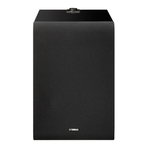
Yamaha SW10 STUDIO User manual

SERVICE MANUAL
HAMAMATSU, JAPAN
SERVICE MANUAL
Copyright (c) Yamaha Corporation. All rights reserved. PDF
&
’06.11
SPECIFICATIONS(総合仕様).................................................3
PANEL LAYOUT(パネルレイアウト)......................................4
CIRCUIT BOARD LAYOUT(ユニットレイアウト).................5
DIMENSIONS(寸法図)............................................................5
DISASSEMBLY PROCEDURE(分解手順)..............................6
IC BLOCK DIAGRAM(IC ブロック図)..................................10
CIRCUIT BOARD(シート基板図).........................................10
INSPECTION and ADJUSTMENT(検査及び調整)...............15
PARTS LIST
BLOCK DIAGRAM(ブロックダイアグラム)
OVERALL CIRCUIT DIAGRAM(総回路図)
CONTENTS(目次)
PA 011841
SW10 STUDIO
Powered Subwoofer
200612-92400

SW10 STUDIO
2
WARNING
WARNING: CHEMICAL CONTENT NOTICE!
The solder used in the production of this product contains LEAD. In addition, other electrical/electronic and/or plastic (Where applicable)
components may also contain traces of chemicals found by the California Health and Welfare Agency (and possibly other entities) to cause
cancer and/or birth defects or other reproductive harm.
DO NOT PLACE SOLDER, ELECTRICAL/ELECTRONIC OR PLASTIC COMPONENTS IN YOUR MOUTH FOR ANY REASON WHAT SO EVER!
Avoid prolonged, unprotected contact between solder and your skin! When soldering, do not inhale solder fumes or expose eyes to solder/
flux vapor!
If you come in contact with solder or components located inside the enclosure of this product, wash your hands before handling food.
IMPORTANT NOTICE
This manual has been provided for the use of authorized Yamaha Retailers and their service personnel. It has been assumed that basic
service procedures inherent to the industry, and more specifically Yamaha Products, are already known and understood by the users,
and have therefore not been restated.
WARNING : Failure to follow appropriate service and safety procedures when servicing this product may result in personal injury,
destruction of expensive components and failure of the product to perform as specified. For these reasons, we advise
all Yamaha product owners that all service required should be performed by an authorized Yamaha Retailer or the
appointed service representative.
IMPORTANT : This presentation or sale of this manual to any individual or firm does not constitute authorization certification,
recognition of any applicable technical capabilities, or establish a principal-agent relationship of any form.
The data provided is belived to be accurate and applicable to the unit(s) indicated on the cover. The research engineering, and service
departments of Yamaha are continually striving to improve Yamaha products. Modifications are, therefore, inevitable and changes in
specification are subject to change without notice or obligation to retrofit. Should any discrepancy appear to exist, please contact the
distributor’s Service Division.
WARNING : Static discharges can destroy expensive components. Discharge any static electricity your body may have accumulated
by grounding yourself to the ground bus in the unit (heavy gauge black wires connect to this bus.)
IMPORTANT : Turn the unit OFF during disassembly and parts replacement. Recheck all work before you apply power to the unit.
Components having special characteristics are marked and must be replaced with parts having specication equal to those
originally installed.
IMPORTANT NOTICE FOR THE UNITED KINGDOM
Connecting the Plug and Cord
WARNING: THIS APPARATUS MUST BE EARTHED
IMPORTANT. The wires in this mains lead are coloured in
accordance with the following code:
GREEN-AND-YELLOW : EARTH
BLUE : NEUTRAL
BROWN : LIVE
As the colours of the wires in the mains lead of this apparatus may
not correspond with the coloured markings identifying the
terminals in your plug proceed as follows:
The wire which is coloured GREEN-and-YELLOW must be
connected to the terminal in the plug which is marked by the letter
E or by the safety earth symbol or colored GREEN or GREEN-
and-YELLOW.
The wire which is coloured BLUE must be connected to the
terminal which is marked with the letter N or coloured BLACK.
The wire which is coloured BROWN must be connected to the
terminal which is marked with the letter L or coloured RED.
印の部品は、安全を維持するために重要な部品です。交換する場合は、安全のために必ず指定の部品をご使用ください。

3
SW10 STUDIO
SPECIFICATIONS
(総合仕様)
*This specification apply to rated power supplies of 100, 120, 230 and 240 V.
GENERAL
Type Powered subwoofer
Overall Frequency Response
Maximum Output Level
Demensions (W x H x D)
Weight 26.5 kg
Yes (None coverd type)Magnetic Shielding
SPEAKER SECTION
Components LF 10" cone
HF
Enclosure Type Bass-Reflex
MDFMaterial
AMPLIFIER SECTION
Output Power * 180W
f = 100 Hz, THD = 1 %, RL = 8 Ω
S/N, IHF-A filter ≧100 dB, LEVEL = Max
Input Sensitivity XLR-3-31
Input Connectors, Impedance XLR-3-31 x 3 (balanced), 10 kΩ
XLR-3-32 x 3 (balanced),
Parallel connection with Input
Controls
Center Click VR
(Min = – ∞ Attenuation)
LOW CUT switch
POWER switch
PHASE switch
on/off
Normal/Reverse
40-120 Hz, 80 Hz at Center Click
Indicators Green: Power On
Red: Clipping
Power Consumption 160 W
AC CORD
2.5 mLength
25 Hz - 150 Hz (-10 dB)
111 dB, 1 m on Axis
328 x 459 x 476 mm
+4 dBu, LEVEL = Center
–6 dBu, LEVEL = Max
Output Connectors
LEVEL control
LPF control
LED

SW10 STUDIO
4
PANEL LAYOUT
' .
<Rear Panel> <Front Panel>
/
4
0(
- 2
(パネルレイアウト)
qPOWER switch
wAC IN connector
ePHASE switch
rHIGH CUT control
tLEVEL control
yINPUT L/R/SUBWOOFER connector
uOUTPUT L/R/SUBWOOFER connector
iPOWER indicator
q POWER スイッチ
w AC IN 端子
e PHASE スイッチ
r HIGH CUT コントロール
t LEVEL コントロール
y INPUT L/R/SUBWOOFER 端子
u OUTPUT L/R/SUBWOOFER 端子
i POWER インジケーター

5
SW10 STUDIO
CIRCUIT BOARD LAYOUT
Unit: mm (inch)
328 (12-15/16”)
459 (18-1/16”) 476 (18-3/4”)
DIMENSIONS
(ユニットレイアウト)
LED
FUSE
POWER
AMP
INPUT
(2/4)
(3/4)
(1/4)
(4/4)
(寸法図)

SW10 STUDIO
6
Front panel
(フロントパネル)
Front panel
(フロントパネル)
LED
Front panel
[A]
(フロントパネル) LED
:
@
DISASSEMBLY PROCEDURE(分解手順)
1. グリル Ass’y(所要時間:約 1 分)
1-1 薄い金尺状のものを本体とグリル Ass’y の間に挿
入し、金尺を外側にずらしてグリル Ass’y を外し
ます。(図 1)
2. フロントパネル(所要時間:約 1 分)
2-1 グリル Ass’y を外します。(1 項参照)
2-2 フロントパネルを外します。(写真 1)
※ フロントパネル裏側に LED シートがあり、本体
から束線がのびています。フロントパネルを外す
際は注意してください。(写真 2)
Fig.1( 図 1)
3. LED シート(所要時間:約 1 分)
3-1 グリル Ass’y を外します。(1 項参照)
3-2 フロントパネルを外します。(写真 1)
3-3 [A] のネジ 2 本を外して、LED シートを外します。
(写真 3)
Photo1( 写真 1)
Photo2( 写真 2)
Photo3( 写真 3)
1. Grille Assembly
(Time required: About 1 minute)
1-1 Insert thin steel measure or the like between the
body and grille assembly and move the measure
outward to remove the grille assembly. (Fig. 1)
2. Front Panel (Time required: About 1 minute)
2-1 Remove the grille assembly. (See procedure 1)
2-2 Remove the front panel. (Photo 1)
※The LED circuit board at the back of the front
panel is connected to the body with the cord
assembly. Be careful not to damage the cord
assembly when removing the front panel.
(Photo 2)
3. LED Circuit Board
(Time required: About 1 minute)
3-1 Remove the grille assembly. (See procedure 1)
3-2 Remove the front panel. (Photo 1)
3-3 Remove the two (2) screws marked [A]. The LED
circuit board can then be removed. (Photo 3)

7
SW10 STUDIO
[50]
(ウーハー)
Speaker unit
[50]
[50]
Rear panel (Control)
[120A]
(リアパネル(コントロール))
Rear panel
(リアパネル)
Rear panel
[136]
(リアパネル)
[120B]
[120B]
[120B]
[120B]
[120A]
4. ウーファー(所要時間:約 2 分)
4-1 グリル Ass’y を外します。(1 項参照)
4-2 [50] のネジ 8 本を外して、ウーファーを外します。
(写真 4)
5. リアパネル(コントロール)、INPUT シート
(所要時間:約 3 分)
5-1 [120A] のネジ 4 本を外して、リアパネル(コント
ロール)を INPUT シートがついた状態で外します。
(図 2)
5-2 [90] のネジ 12 本を外して、リアパネル(コントロー
ル)と INPUT シートを分離します。(写真 5)
6. リアパネル(所要時間:約 1 分)
6-1 [120B] のネジ 6 本と [136] のネジ 1 本を外して、
リアパネルを外します。(図 2)
Photo4( 写真 4)
[120]:BindHeadTappingScrew-B(B タイト+ BIND)4.0X10NI-BL(WJ285200)
[136]:BindHeadTappingScrew-B(B タイト+ BIND)4.0X8
[50]:BindHeadScrew(小ネジ+ BIND)4.0X25(WJ285000)
Fig.2( 図 2)
4. Speaker Unit (Time required: About 2 minutes)
4-1 Remove the grille assembly. (See procedure 1)
4-2 Remove the eight (8) screws marked [50]. The
speaker unit can then be removed. (Photo 4)
5. Rear Panel (Control), INPUT Circuit Board
(Time required: About 3 minutes)
5-1 Remove the four (4) screws marked [120A]. The
rear panel (control) can then be removed with the
INPUT circuit board attached. (Fig. 2)
5-2 Remove the twelve (12) screws marked [90] and
separate the INPUT circuit board from the rear
panel (control). (Photo 5)
6. Rear Panel (Time required: About 1 minute)
6-1 Remove the six (6) screws marked [120B] and the
screw marked [136]. The rear panel can then be
removed. (Fig. 2)

SW10 STUDIO
8
[35]
[35]
[25]
[25]
[45]
Holder B
(ホルダー B) Holder A
(ホルダー A)
[45]
POWER
:
@
.
;
:
@
.
;
[90]
[90]
INPUT
Rear panel, Control
(リアパネル(コントロール))
AMP
Spacer
(スペーサー)
Spacer
(スペーサー)
POWER
Spacer
(スペーサー)
Spacer
(スペーサー)
7. AMP シート(所要時間:約 2 分)
7-1 リアパネル(コントロール)を外します。(5-1 項参照)
7-2 リアパネルを外します。(6 項参照)
7-3 スペーサーのツメ 4 個所を外して、AMP シート
を外します。(写真 6)
8. POWER シート(所要時間:約 4 分)
8-1 リアパネル(コントロール)を外します。(5-1 項参照)
8-2 リアパネルを外します。(6 項参照)
8-3 AMP シートを外します。(7 項参照)
8-4 [25] のネジ 4 本と [35] のネジ 4 本を外して、ホル
ダー A とホルダー B を外します。(写真 7)
※ ホルダー A とホルダー B を取り付けるときは、写
真 7 の番号順にネジを締めてください。(写真 7)
8-5 [45] のネジ 4 本を外して、POWER シートを外し
ます。(写真 7)
8-6 POWER シートからスペーサー 4 個を外します。
(写真 8)
[90]:BindHeadTappingScrew-B(B タイト+ BIND)3.0X10NI-BL(WH042000)
Photo5( 写真 5)
Photo6( 写真 6)
Photo7( 写真 7)
Photo8( 写真 8)
7. AMP Circuit Board
(Time required: About 2 minutes)
7-1 Remove the rear panel (control). (See procedure 5-1)
7-2 Remove the rear panel. (See procedure 6)
7-3 Release the four (4) claws of the spacers and re-
move the AMP circuit board. (Photo 6)
8. POWER Circuit Board
(Time required: About 4 minutes)
8-1 Remove the rear panel (control). (See procedure 5-1)
8-2 Remove the rear panel. (See procedure 6)
8-3 Remove the AMP circuit board. (See procedure 7)
8-4 Remove the four (4) screws marked [25] and four
(4) screws marked [35].The holder A and holder B
can then be removed. (Photo 7)
※When installing the holder A and holder B, tight-
en the screws in numerical order as shown in
Photo 7. (Photo 7)
8-5 Remove the four (4) screws marked [45]. The POW-
ER circuit board can then be removed. (Photo 7)
8-6 Remove the four (4) spacers from the POWER cir-
cuit board. (Photo 8)
[25]:BindHeadScrew(小ネジ+ BIND)3.0X12
[35]:BindHeadScrew(小ネジ+ BIND)3.0X12
[45]:BindHeadScrew(小ネジ+ BIND)3.0X6BL

9
SW10 STUDIO
[15]
[55]
Power transformer
(トランスパワー)
[15]
[55]
FUSE
[139] [139]
AC Inlet
(AC インレット)
AC Inlet
(AC インレット)
Claw
(ツメ)
Switch
(パワースイッチ)
Switch
(パワースイッチ)
<Surface>
<Reverse side>
• Rear panel
9. トランスパワー(所要時間:約 2 分)
9-1 リアパネルを外します。(6 項参照)
9-2 [15] のネジ 4 本を外して、トランスパワーを外し
ます。(写真 9)
10. FUSE シート(所要時間:約 1 分)
10-1 リアパネルを外します。(6 項参照)
10-2 [55]のネジ2本を外して、FUSEシートを外します。
(写真 9)
11. AC インレット、パワースイッチ
(所要時間:各約 1 分)
11-1 リアパネルを外します。(6 項参照)
11-2 AC インレット
11-2-1 [139] のネジ 2 本を外して、リアパネルから AC イ
ンレットを外します。(写真 10)
11-3 パワースイッチ
11-3-1 内側のツメを押さえながら、リアパネルからパ
ワースイッチを引き抜きます。(写真 10)
Photo9( 写真 9) Photo10( 写真 10)
9. Power Transformer
(Time required: About 2 minutes)
9-1 Remove the rear panel. (See procedure 6)
9-2 Remove the four (4) screws marked [15]. The
power transformer can then be removed. (Photo 9)
10. FUSE Circuit Board
(Time required: About 1 minute)
10-1 Remove the rear panel. (See procedure 6)
10-2 Remove the two (2) screws marked [55]. The
FUSE circuit board can then be removed. (Photo 9)
11. AC Inlet, Switch
(Time required: About 1 minute each)
11-1 Remove the rear panel. (See procedure 6)
11-2 AC Inlet
11-2-1 Remove the two (2) screws marked [139]. The AC
inlet can then be removed from the rear panel.
(Photo 10)
11-3 Switch
11-3-1 While holding down the inside claws, pull out the
switch from the rear panel. (Photo 10)
[15]:BindHeadScrew(小ネジ+ BIND)4.0X8
[55]:BindHeadScrew(小ネジ+ BIND)3.0X6BL [139]:FlatHeadScrew(皿ネジ+ BIND)3.0X8BL

SW10 STUDIO
10
NJM072D (X8346A00)
INPUT : IC101, IC102
NJM4560D (X8347A00)
AMP : IC201, IC202
INPUT : IC103, IC104
Dual Operational Amplifier
1
2
3
4 -V
8
7
6
5
Output A +V
Non-Inverting
Input A
-DC Voltage Supply
+DC Voltage
Supply
Output B
Inverting
Input B
Non-Inverting
Input B
Inverting
Input A
+ -
+ -
to AC Inletto Power switch to Power transformer
CIRCUIT BOARDS(シート基板図)
AMP (3/4) Circuit Board (6484c-30) ......................................................... 14
FUSE (1/4) Circuit Board (6484a-30) ....................................................... 10
INPUT (2/4) Circuit Board (6484b-30) ...................................................... 11
LED (4/4) Circuit Board (6484d-30).......................................................... 10
POWER Circuit Board (8145-30).............................................................. 12
Note: See parts list for details of circuit board component parts.
注 : シートの部品詳細はパーツリストをご参照ください。
IC BLOCK DIAGRAM(IC ブロック図)
to POWER-CN501
FUSE (1/4) Circuit Board
Component side(部品側)
LED (4/4) Circuit Board
Component side(部品側)

15
SW10 STUDIO
INSPECTION and ADJUSTMENT(検査及び調整)
MEASURING VOLTAGE(測定電圧) : J AC 100 V 50/60 Hz
U,T AC 120 V 60 Hz
B,H,K,O AC 230 V 50 Hz
A AC 240 V 50 Hz
LOAD(負荷) : 8Ω
INPUT(入力) : INPUT1
VR-LEVEL : MAX.
CUTOFF FREQ : 120 Hz
PHASE : NORM
Electric performance(電気性能)
ITEM(項目) INPUT CONDITIONS
(入力条件)
OUTPUT CONDITIONS
(出力条件)
LIMIT
(限界値)
GAIN(利得)
INPUT1 : –20 dBu, 30Hz
SP 27.8 ± 2 dBu
INPUT2 : –20 dBu, 30Hz
INPUT3 : –20 dBu, 30Hz
INPUT1 : –20 dBu, 30Hz OUTPUT (THRU) 1
–20.5 ± 0.5 dBuINPUT2 : –20 dBu, 30Hz OUTPUT (THRU) 2
INPUT3 : –20 dBu, 30Hz OUTPUT (THRU) 3
T. H. D.(ひずみ率) INPUT1 : 100 Hz 38 V OUTPUT SP 1.0 %
OUTPUT NOISE LEVEL
(出力ノイズレベル) INPUT1,2,3:LORD600Ω
VR: MIN
IHF-A FILTER
SP
–70 dB
VR: MAX
IHF-A FILTER –68 dB
FREQUENCY
CHARACTERISTIC
(周波数特性)
INPUT1 : 20 Hz REF:
INPUT1 : 30 Hz
OUTPUT : 0 dBu
CUTOFF FREQ : 120 Hz
SP
–6 ± 3 dBu
INPUT1 : 50 Hz –6.5 ± 2.0 dBu
INPUT1 : 100 Hz –12.5 ± 2.0 dBu
INPUT1 : 20 Hz REF:
INPUT1 : 30 Hz
OUTPUT : 0 dBu
CUTOFF FREQ : 40 Hz
–5 ± 3.5 dBu
INPUT1 : 50 Hz –11.0 ± 2.5 dBu
INPUT1 : 100 Hz –27.5 ± 4.0 dBu
(NOTE): 0 dBu = 0.775 V

SW10 STUDIO
16
FACTORY SETTING(出荷時の設定)
Power On-Muting Time(POWERON-MUTING 時間)
Turn on the power switch and the muting will be canceled and the relay will be turned on. Check that the time difference is 3
±1 seconds after the power switch is turned on.
POWER SWITCH を ON 後、t = 3 ± 1 秒にて MUTING が解除され、RELAY が ON することを確認します。
Adjusting Idle Current(Idling 電流の調整)
Adjust the VR351 and VR451 so that the voltage between the qand wof the CN351 and CN451 is 0.7±0.15 mV
respectively. (Photo 1)
After all the inspections are over, inspect the voltage between the qand wof the CN351 and CN451 again and adjust the
VR351 and VR451 so that the voltage is 0.7±0.15 mV. (Photo 1)
CN351, CN451 の①〜②間の電圧がそれぞれ 0.7 ± 0.15 mV になるように VR351,
VR451 を調整します。(写真 1)
全検査後、再度 CN351, CN451 の①〜②間の電圧の検査を行い、0.7 ± 0.15 mV に
なるように VR351, VR451 を調整します。(写真 1)
Midpoint Potential(中点電位)
Check that the voltage between the SPEAKER terminals is ±100 mV or less when
no signal is input.
無信号時において SPEAKER 端子間電圧は± 100 mV 以下であることを確認します。
PHASESW
Check that the signal is out of phase with the input signal by 180 degrees when the PHASE switch is switched.
PHASE SW を切り替えたとき入力信号に対し位相が 180 度変化することを確認します。
Stability(安定度)
1: Check that there is no oscillation or the like when the power supply is changed by ±10%.
2: Connect the load with the following capacity to the SPEAKER terminals and check that there is no oscillation or the like.
1: 電源電圧を± 10 %変化させたとき、発振などを生じないことを確認します。
2: スピーカー端子に下記容量負荷を接続し、発振等を生じないことを確認します。
①②③④⑤⑥⑦⑧⑨⑩
Capacity(容量) 47p 100p 330p 470p 1000p 3300p 4700p 0.01µ0.033µ0.047µ
Protection circuit(保護回路)
Disconnect the wire CN202 from the CONNECTOR and check that the RELAY will be turned off within one (1) second.
ReconnectthewiretotheCONNECTORandcheckthattheRELAYwillbeturnedonwithinve(5)seconds.
CN202 の線材を CONNECTOR から外したとき、1 秒以内に RELAY が OFF することを確認します。
再びコネクタに挿入し、5 秒以内に RELAY が ON することを確認します。
• POWER : OFF
• PHASE : NORM.
• HIGH CUT : MAX (120)
• LEVEL : MIN (0)
VR351 VR451VR351
CN351
CN451
CN351
CN451
VR451
POWER AMP
Photo 1(写真 1)

PARTS LIST
WARNING
Components having special characteristics are marked and must be replaced with parts having
specication equal to those originally installed.
• The numbers “QTY” show quantities for each unit.
• The parts with “--” in “PART NO.” are not available as spare parts.
• This mark “ } ” in the REMARKS column means these parts are interchangeable.
• The second letter of the shaded ( ) part number is O, not zero.
• The second letter of the shaded ( ) part number is I, not one.
• 部品価格ランクは、変更になることがあります。
• QTY 欄に記されている数字は、各ユニット当たりの使用個数です。
• PART NO. が“--”の部品は、サービス用部品として準備されておりません。
• REMARKS 欄の「 } 」マークの部品は、併用部品です。
• 網掛けの付いた PART NO. の 2 番目の文字は「ゼロ」ではなく、「オー」です。
• 網掛けの付いた PART NO. の 2 番目の文字は「イチ」ではなく、「アイ」です。
Notes : DESTINATION ABBREVIATIONS
A : Australian model
B : British model
C : Canadian model
D : German model
E : European model
F : French model
H : North European model
I : Indonesian model
J : Japanese model
K : Korean model
M : South African model
O : Chinese model
Q : South-east Asia model
T : Taiwan model
U : U.S.A. model
V : General export model (110V)
W: General export model (220V)
N,X: General export model
Y : Export model
印の部品は、安全を維持するために重要な部品です。交換する場合は、安全のために必ず指定の部品を
ご使用ください。
CONTENTS(目次)
OVERALL ASSEMBLY(総組立)
..................................... 2
AMP ASSEMBLY(AMP Ass'y)
....................................... 4
ELECTRICAL PARTS(電気部品)
................................... 6
SW10 STUDIO
Powered Subwoofer

REF NO. PART NO. DESCRIPTION 部品名 REMARKS QTY
RANK
*: New Parts RANK: Japan only
3
SW10 STUDIO
OVERALL ASSEMBLY 総組立SW10 STUDIO
-- Oversll Assembly J総組立J
-- Oversll Assembly U,C 総組立U
-- Oversll Assembly H総組立H
-- Oversll Assembly BS 総組立B
-- Oversll Assembly A総組立A
-- Oversll Assembly KT 総組立K
-- Oversll Assembly CHN 総組立O
-- Oversll Assembly TT 総組立T
*10 WJ281000 Enclosure Assembly
エンクロージャーAss’y
*20 WJ278600 Grille Assembly グリルAss’y 443005
*20a WJ279900 Name Logo AL ロゴバッジ 447802
20b -- Nut ナット 042382 2
*30 WJ274800 Front Panel フロントパネル 442528
*40 X8359A00 Speaker Unit ウーハー 450110
*50 WJ285000 Bind Head Screw 4.0X25 小ネジ+BIND 442242 8
60 -- AMP Assembly アンプAss’y J 435993
60 -- AMP Assembly アンプAss’y U 436164
60 -- AMP Assembly アンプAss’y H 436167
60 -- AMP Assembly アンプAss’y B 436166
60 -- AMP Assembly アンプAss’y A 436165
60 -- AMP Assembly アンプAss’y K 436169
60 -- AMP Assembly アンプAss’y O 436170
60 -- AMP Assembly アンプAss’y T 444467
*70 WJ285100 Bind Head Screw 5.0X30 小ネジ+BIND 447931 8
*WJ281000 Enclosure Assembly
エンクロージャーAss’y
*E10 WJ280900 Cabinet キャビネット 442151
*E20 WJ280400 Duct A ダクトA 441977
*E30 WJ280500 Duct B ダクトB 441846
*E40 WJ280600 Damping Material 1300X300X20 吸音材 446654
*E50 WJ280700 Damping Material 417X286X20 吸音材 446658
*E60 WJ280800 Grille Catch グリルキャッチ 020799 10
*E70 WJ285300 M4-Nut M4−NUT 447953 8
*E80 WJ285400 M5-Nut M5−NUT 447852 8
*E90 WJ496800 Seal シール 042490 2
*E100 WJ496900 Cord Assembly コードAss’y 449337
*E100a WJ497100 Cushion 160X40X3 クッション 430322
*E100b WJ497200 Cushion 140X35X3 クッション 430333
ACCESSORIES 付属品
WG261700 AC Cord 電源コードJ 414427 08
WG261800 AC Cord 電源コードU 369532 08
WG262000 AC Cord 電源コードH,A,K 417976 08
WH221600 AC Cord 電源コードB 417977 12
WG262200 AC Cord 電源コードO 414426 12
WH667300 AC Cord 電源コードT 444018

SW10 STUDIO
4
AMP ASSEMBLY(AMP Ass'y)
[35]
[40]
[35]
[25]
[25]
[45] [22][32] Holder B
(ホルダー B) Holder A
(ホルダー A)
[45]
100
110
110
3
120
139
120
130
140
140130
133 131 141
136135
10
15
5
7
7
30
32
3
160
160
70
90
80
20
22
25
35
40
45
47
49
49
49
60
50
55
Front panel
142132
Refer to on pages 2 and 3 for information on cord assembly.
*
*
(コードAssyは2,3ページのを参照してください。)
*
E100
E100
Other manuals for SW10 STUDIO
3
Table of contents
Other Yamaha Subwoofer manuals

Yamaha
Yamaha SW500 User manual

Yamaha
Yamaha SW500 User manual

Yamaha
Yamaha SW-2 User manual

Yamaha
Yamaha YST-SW320 User manual

Yamaha
Yamaha KS-SW100 User manual

Yamaha
Yamaha DXS15 mkll User manual

Yamaha
Yamaha YST-MSW5 User manual

Yamaha
Yamaha YST-SW320 User manual

Yamaha
Yamaha GNS-MS01 User manual

Yamaha
Yamaha YST-SW010 User manual

Yamaha
Yamaha IS1215 User manual

Yamaha
Yamaha YST-FSW150 User manual

Yamaha
Yamaha HTY-760 User manual

Yamaha
Yamaha NS-SW210 User manual

Yamaha
Yamaha YST-SW012 User manual

Yamaha
Yamaha NS-SW300 User manual

Yamaha
Yamaha MSR800W User manual

Yamaha
Yamaha NS-SW500 User manual

Yamaha
Yamaha NS-SW300 User manual

Yamaha
Yamaha YST-SW216 User manual