Yamaha DX100 User manual

YAMAHA
n1i^
irni
DIGITAL PROGRAMMABLE ALGORITHM SYNTHESIZER
SYNTHETISEUR NUMERIQUE AALGORITHMES
PROGRAMMABLES
DIGITAL PROGRAMMIERBARER ALGORITHMUS
SYNTHESIZER
OWNER'S MANUAL
MANUEL D'UTILISATION
BEDIENUNGSANLEITUNG

CONGRATULA TIONS!
Your Yamaha DX100 Digital Programmable Algorithm Synthesizer incorporates state-
of-the-art digital FM tone generation technology, providing extraordinarily vibrant, rich
voices and outstanding payability. The DX1 00 has aprogrammable 24-voice INTERNAL
memory (RAM) from which any voice can be selected at the touch of abutton, two
96-voice PRESET (ROM) memories (a total of 192 fine preset voices!), a96-voice BANK
memory that permits storage of PRESET voices in any configuration for one-touch se-
lection, and acassette interface that permits unlimited storage of FM voices. Of course,
the DX100 is fully programmable, allowing you to create your own FM voices or sound
effects. Broad MIDI compatibility is also provided so the DX1 00 can control or be
controlled via other MIDI-compatible music equipment.
To ensure that you gain maximum benefit from all the performance and flexibility provided
by the DX1 00, we urge you to read this owner's manual thoroughly while actually trying
out all of the available functions. c*
CONTENTS
CHAPTER I: SETTING UP 3
1. Audio Outputs 3
2. Optional Foot Switch 3
3. Optional BC-1 Breath Controller 3
4. Headphones 3
5. MIDI Terminals 3
6. Cassette 3
7. Battery, AC Power Adaptor 3
8. Power-ON, Low Battery LED Indicator 4
9. LCD Contrast Control 4
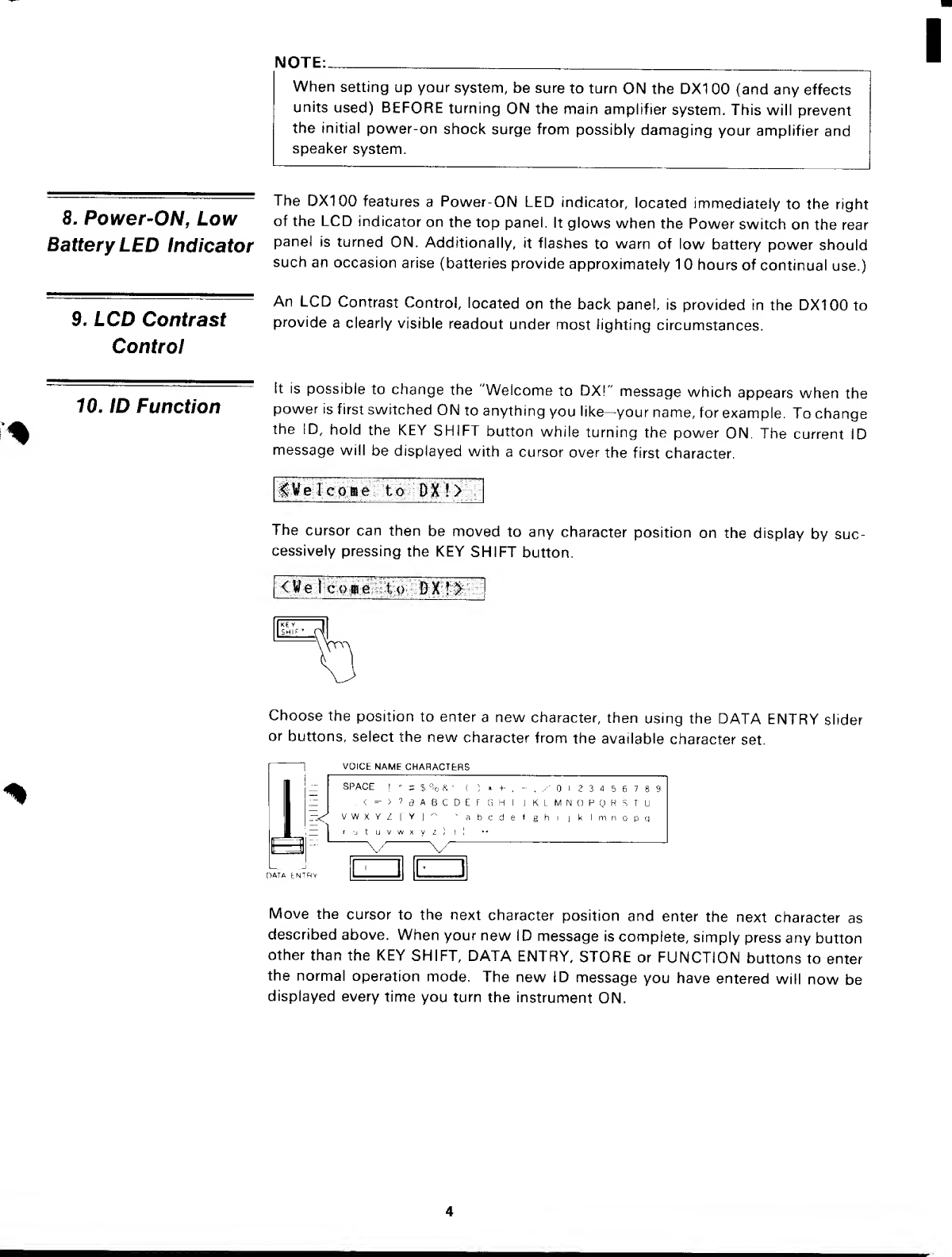
10. ID Function 4
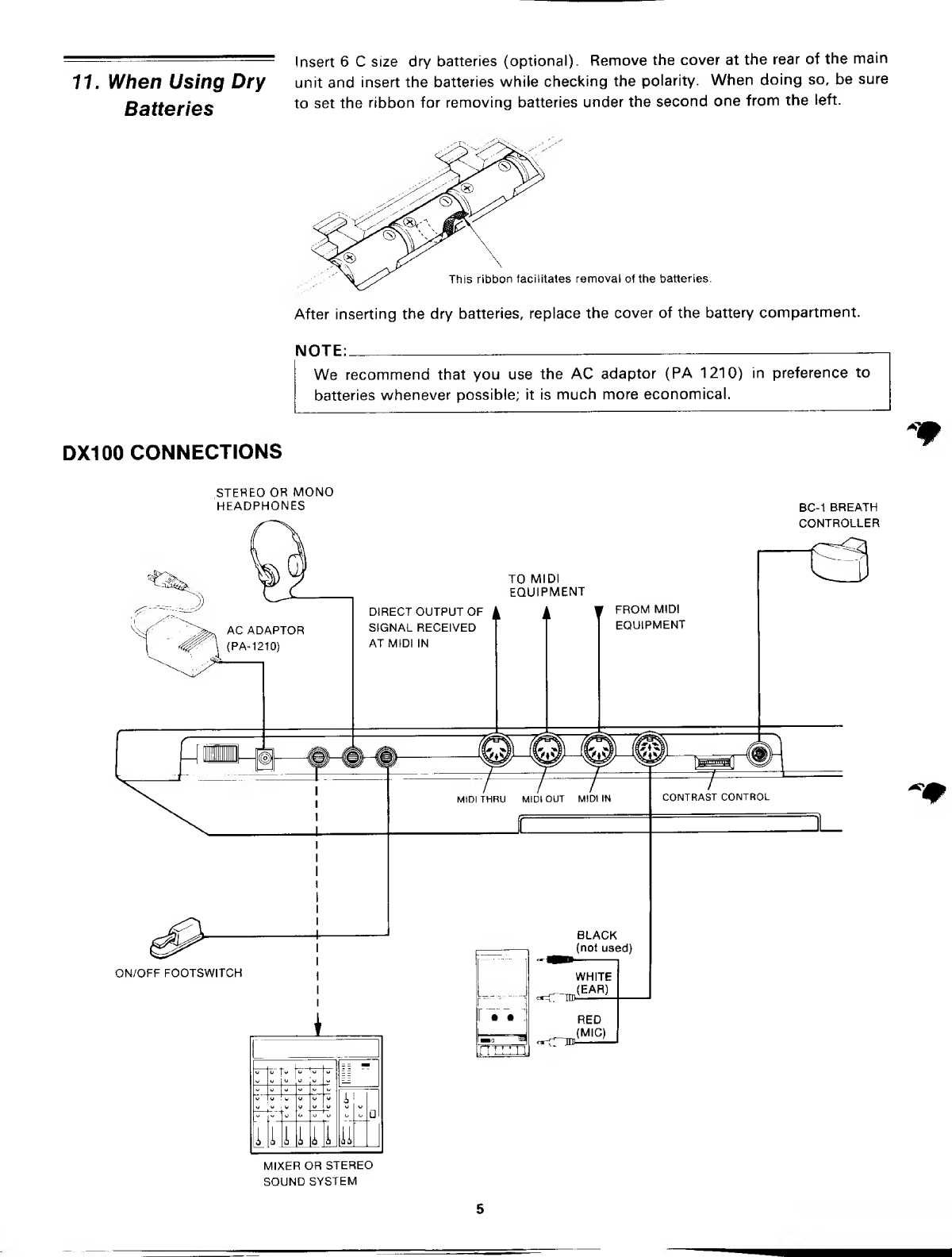
11. When Using Dry Batteries 5
CHAPTER II: PLAYING THE DX100 6
1. DX100 Voice Memory Configuration 6
2. The INTERNAL PLAY Mode 7
3. The BANK PLAY Mode 8
The SHIFT Mode 8
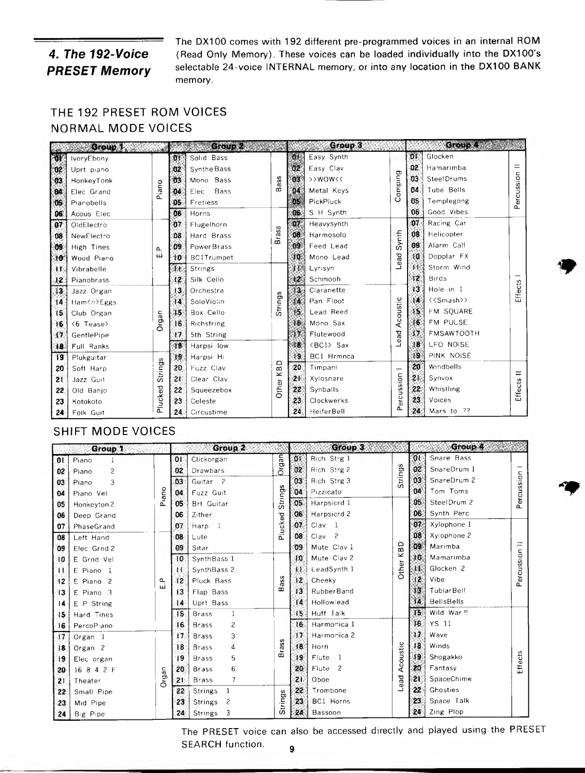
4. The 192-Voice PRESET Memory 9
PRESET SEARCH 10
CHAPTER III: THE FUNCTION MODE 11
1. Accessing the FUNCTION Mode 11
2. Entering Function Data 11
"3. The Performance Parameters 11
4. Tuning Functions 17
5. Memory Management Functions 17
6. MIDI Functions 22
CHAPTER IV: VOICE PROGRAMMING 24
1. The Basics of FM Synthesis 24
2. The EDIT and COMPARE Modes 29
3. The Voice Parameters 30
4. Storing Voice Data 38
5. Two Approaches to Creating Your Own Voices 38
CHAPTER V: VOICE PROGRAMMING EXAMPLE 40
GENERAL SPECIFICATIONS 44
MIDI DATA FORMAT 45
1. Transmission Conditions 45
2. Transmission Data 46
3. Reception Conditions 49
4. Reception Data 50
5. System Exclusive Data 53
VOICE/FUNCTION DATA 57
DATA NAME 58
c+

PRECAUTIONS
%
7. Location
2. Cleaning
3. Service and
Modifications
4. Relocation
5. Handling
6. Electrical Storms
(Lightning)
7. Electromagnetic
Fields
Avoid locations exposed to direct sunlight or other sources of heat. Also avoid
locations subject to vibration, excessive dust, cold or moisture.
Do not attempt to clean the exterior with chemical solvents; this may damage the
finish. Clean with asoft, dry cloth.
Do not open the DX100 or attempt to make your own repairs or modifications to
any part of the instrument. Such actions may not only result in electrical shock or
damage, but will also void the product warranty. Refer all servicing to aqualified
Yamaha service center.
When moving the instrument be sure to unpfug the AC adaptor (PA-1 21 0, optional)
as well as all other connecting cables.
Avoid applying excessive force to switches and slide controls, dropping or rough
handling. The DX1 00 is ruggedly constructed using reliable solid-state circuitry,
but it is still afine instrument and should be treated with care.
Digital circuitry, such as that used in the DX1 00, is sensitive to voltage spikes and
surges. Be sure to remove all connecting cables in the event of an electrical storm.
Digital circuitry is also sensitive to electromagnetic fields such as those produced
by television sets, radio receivers, transmitters, transceivers, etc. The DX1 00 should
be kept several feet away from any such sources in order to prevent possible random
malfunctions.

CHAPTER I: SETTING UP
1. Audio Outputs
2. Optional Foot
Switch
3. Optional BC-7
Breath Controller
4. Headphones
5. MIDI Terminals
6. Cassette
7. Battery, AC Power
Adaptor
The DX100 has asingle mono audio output for its tone generator channel. This
is labelled OUTPUT. It permits sending amono signal to either amono or stereo
sound system, or amixing console for recording or PA applications.
The FOOT SW phone jack is for an optional footswitch. It accepts aYamaha FC-4
or FC-5 footswitch or equivalent for portamento/sustain control; press for sustain
or portamento release to damp or turn portamento off.
Yamaha's unique BC-1 breath controller is plugged into the mini-jack on the rear
panel.
The PHONES jack accepts any standard pair of stereo headphones. The audio signal
is sent to the headphones in mono. Headphone volume is controlled by the VOLU M
E
control on the top panel.
These terminals are used when connecting the DX100 to other MIDI (Musical
Instrument Digital Interface) compatible equipment such as digital sequence re-
corders, modular FM voice generators, drum machines, etc. The MIDI OUT terminal
transmits MIDI data from the DX1 00 to other MIDI equipment. The MIDI OUT
terminal will normally be connected to the MIDI IN terminal of the receiving
equipment. The MIDI IN terminal receives MIDI data from external MIDI equipment
such as adigital sequence recorder, music computer or modular FM voice generator.
The DXIOO's MIDI IN terminal will normally be connected to the MIDI OUT terminal
of the transmitting equipment. The MIDI THRU terminal re-transmits the data re-
ceived at the MIDI IN terminal. Thus, data received via the DX100 MIDI IN terminal
can be simultaneously sent to other MIDI equipment.
The DIN connector end of the supplied cassette cable is plugged into the DX1 00
CASSETTE connector. The three plugs on the other end of the cable should be
connected to acassette data recorder (the kind normally used with personal
computers, etc.) as follows:
RED -* cassette deck microphone input.
WHITE -> cassette deck earphone output.
BLACK -» cassette deck remote input (where applicable).
The DX100 operates off 6"C" size batteries which are inserted in the battery
compartment at the bottom of the synthesizer. To operate the DX100 from an AC
power outlet, insert the optional PA-1210 AC power adaptor cord into the DC IN
jack located on the rear panel of the DX100, and then plug the standard 2-prong
plug into an AC wall socket. Be sure that your local line voltage matches that
specified on the PA-1 21 0. You will find the POWER switch next to the DC IN jack
on the rear panel of the DX100.

NOTE:,
When setting up your system, be sure to turn ON the DX1 00 (and any effects
units used) BEFORE turning ON the main amplifier system. This will prevent
the initial power-on shock surge from possibly damaging your amplifier and
speaker system.
The QX100 features aPower-ON LED indicator, located immediately to the right
8. Power-ON, LOW of the LCD indicator on the top panel. It glows when the Power switch on the rear
Battery LED Indicator Panel is turned 0N -Additionally, it flashes to warn of low battery power should
such an occasion arise (batteries provide approximately 1hours of continual use.)
9. LCD Contrast
Control
An LCD Contrast Control, located on the back panel, is provided in the DX100 to
provide aclearly visible readout under most lighting circumstances.
70. ID Function It is possible to change the 'Welcome to DX!" message which appears when the
power is first switched ON to anything you like-your name, for example. To change
the !D, hold the KEY SHIFT button while turning the power ON. The current ID
message will be displayed with acursor over the first character.
fWelcome to DX!>
The cursor can then be moved to any character position on the display by suc-
cessively pressing the KEY SHIFT button.
<Welcome to DX!t
Choose the position to enter anew character, then using the DATA ENTRY slider
or buttons, select the new character from the available character set.
VOICE NAME CHARACTERS
-<
SPACE !"=$%X'(}*+-.-. y' I2345678
:<=" >?dA6CDEF'GH IJKLMNOPQRSTU
VWXYZ[' YJ-~abcdefghijkImnopq
rytu v WxyIi! !
"^
Move the cursor to the next character position and enter the next character as
described above. When your new ID message is complete, simply press any button
other than the KEY SHIFT, DATA ENTRY, STORE or FUNCTION buttons to enter
the normal operation mode. The new ID message you have entered will now be
displayed every time you turn the instrument ON.

-Insert 6Csize dry batteries (optional). Remove the cover at the rear of the main
11. When Using Dry unit and insert the batteries while checking the polarity. When doing so, be sure
Batteries t0 set ^er'DDon f°rremoving batteries under the second one from the left.
This ribbon facilitates removal of the batteries.
After inserting the dry batteries, replace the cover of the battery compartment.
DX1 00 CONNECTIONS
NOTE:
We recommend that you use the AC adaptor (PA 1210) in preference to
batteries whenever possible; it is much more economical.
*W
STEREO OR MONO
HEADPHONES
AC ADAPTOR
^P^ \(PA-1210)
ON/OFF FOOTSWITCH
BC-1 BREATH
CONTROLLER
TO MIDI
EQUIPMENT
DIRECT OUTPUT OF ^
SIGNAL RECEIVED
AT MIDI IN
FROM MID!
EQUIPMENT
:H: t":T^
u"a
ill' 1
—i—
i
ii 11 H
MIXER OR STEREO
SOUND SYSTEM
MIDI THRU MIDI OUT MIDI IN
BLACK
(not used)
«=rTTD.
WHITE
(EAR)
t_cTTnt
RED
(MIC)
CONTRAST CONTROL *m

I
CHAPTER II: PLA YING THE DX700
i» i1,l s» ,1 ».1 *f a. ^, mj
ALGORITHM FEEDBACK WAVE MODULATION SENSITIVITY
AMPLITUDE EG BIAS KEY VELOCITY
1' II |2 I
CHANNEL
ENVELOPE
1| |U 11 IP II
SYS INFO IP—11' 115—119 II |L£_ |l« IIh2 1
MASTER ON-OFF
MIDI
DETUNL
CH INFO
GENERATOR
RECALL
EDIT INIT
VOICE EDIT
BANK
OPERATOR
OUT LEVEL
SAVE/VERIFY LOAD LOAD SINGLE MEMORY
1UFNt AUJ
OSCILLATOR
CASSETTE
KEYBOARD SCALING
F-Horbcr
FREQ RATIO AR D1R D1L D2R RR RATE LEVEL TRANSPOSE
|13 II [14 J
:MODE TIME Jl IL!Z II |M9
PITCH Jl L2 1|
AMPLITUDE
||20
PITCH -Jl 121 l| [1 22
AMPLITUDE PITCH _l !23 I|l24 1
POLY MONO PITCH BEN FOOT sw BIAS EG BIAS VOICE NAME
PORTAMENTO WHEEL RANGE BREATH RANGE
^
1. DX100 Voice
Memory
Configuration
The DX1 00 has three different voice memories which serve different purposes. They
are:
The 24-voice INTERNAL memory.
This voice memory is used for quick selection of voices for performance, and it is
to this memory that original voices you have edited or programmed are initially
stored. Cassette LOAD and STORE operations are also carried out to and from the
24-voice INTERNAL memory. Voices from the 192-voice PRESET memory may
also be stored in the INTERNAL memory.
The 96-voice BANK memory (4 BANKS x24 voices each).
The BANK memory incorporates four 24-voice BANKS-A, B, Cand D. The BANK
is most useful for storing groups of voices you have arranged for specific purposes.
The different banks may be programmed with different voice groups you need for
different "sets" in aperformance, or you can categorize your voices into BANKs
(i.e. piano-type voices in one bank, brass in another, etc.), or any combination you
like. The BANK can be loaded with voices from the PRESET memory (described
below) or from the INTERNAL memory using the EDIT BANK function.
The 192-voice PRESET memory.
This is aread-only memory which contains 192 FM voices. These are organized
into two groups of 96 voices each. The first group is accessible in the NORMAL

mode, while the second group is accessed in the SHIFT mode (these modes will
be described below). These voices may be selected and stored in the BANK or
INTERNAL memories as desired. They can also be directly accessed and played
using the PRESET SEARCH function.
The chart below shows the overall DX1 00 voice memory configuration. The VOICE
EDIT BUFFER is aspecial memory into which avoice is placed when selected.
Whether avoice is selected from the INTERNAL memory, the BANK memory, or
the PRESET memory, it is placed in the VOICE EDIT BUFFER where it can be played,
edited, stored in another memory location or saved on cassette.
INITIAL VOICE
PARAMETERS
CINIT VOICE J
I
(PRESET SEARCH}
BACKUP VOICE
BUFFER
EDIT RECALL
VOICE EDIT BUFFER
(FM TONE GENERATOR)
192-VOICE PRESET MEMORY
NORMAL MODE GROUP
101 -424
TT
SHIFT MODE GROUP
101 ~424
3C
96-VOICE BANK MEMORY
BANK A. BANK B,
BANK C, BANK D
<>
DG
LOAD SINGLE
24 VOICE INTERNAL
MEMORY
1~24
DATA
CASSETTE
RECORDER
NOTE:
The voices in the PRESET memory are numbered as follows: each group of
96 voices—the NORMAL group and the SHIFT group—is further subdivided
into four groups of 24 voices each (101-124, 201-224, 301-324, and
401—424). Thus you have NORMAL group voices 101—424, and SHIFTgroup
voices 101—424.
*m
2. The INTERNAL
PLAY Mode
To access the 24-voice INTERNAL memory, enter the INTERNAL PLAY mode by
pressing the INTERNAL PLAY button. Next, select avoice from the INTERNAL
memory by pressing the corresponding voice selector button (1—24). At this point,
the LCD display will indicate the voice number and voice name. These are preceded
by a"?," indicating that the INTERNAL PLAY mode has been selected.
P1Ivory Ebony

3. The BANK PLAY
Mode
In this mode, you can play any of the voices currently in the DXIOO's 24-voice
INTERNAL memory individually.
The BANK PLAY mode enables you to access the 96 BANK memory locations.
These initially contain the first group of 96 voices from the 192-voice PRESET
ROM. By using the SHIFT mode, however, you can also access the second group
of presets while in the BANK PLAY mode. Later, you can store any voices you like
in any order in any of the BANKS.
While in the INTERNAL PLAY mode, press any of the BANK buttons; BANK
A—BANK D. This will select the appropriate BANK, and the 24 voices in that bank
can be selected by pressing any of the DXIOO's 24 voice buttons.
I
The SHIFT Mode
By entering the DX100 SHIFT mode while in BANK PLAY, the correspondingly
numbered voice from the second (SHIFT) group of preset voices will be selected.
Note that in the BANK PLAY mode this only applies to voices which have been
stored in the BANK memory from the 192-voice PRESET memory. Voices stored
in the BAN Kfrom the 24-voice INTE RNAL memory will not change when the SH IFT
mode is selected.
To enter the SHIFT mode, hold down the INTERNAL PLAY button and press the
+1button. To return to the NORMAL mode hold down the INTERNAL PLAY button
and press the -1 button.
SHIFT mode
NORMAL mode

4. The 192-Voice
PRESET Memory
The DX100 comes with 192 different pre-programmed voices in an internal ROM
(Read Only Memory). These voices can be loaded individually into the DXIOO's
selectable 24-voice INTERNAL memory, or into any location in the DX100 BANK
memory.
THE 192 PRESET
NORMAL MODE ROM VOICES
VOICES
^'^Jf^W&Jk ,«• Group 2.. .
'•.-' Group 3
^
oroiife *':":-. pr
•§' IvoryEbony of Solid Bass ^Easy Synth or Glocken
lUf Uprt piano 02 SyntheBass 02 Easy Clav Ui 02 Hamarimba
03 HonkeyTonk o03 Mono Bass to 03 >>WOW<< a. 03 SteelDrums o
04 Elec Grand 04 Elec Bass co 04. Metal Keys o04 Tube Bells o
cE
_
05
08
Pianobells
Acous Elec
Q_ 05 Fretless ;:osfe
0$
PickPluck
SHSynth
O05
06
Templegong
Good Vibes
06
07
Horns
Flugelhorn to
*m OldElectro ''#:. Heavysynth 07 Racing Car
08 NewElectro 06 Hard Brass Cf)
ro 06 Harmosolo 08 Helicopter
09 High Tines Q_ 09 Power Brass CD 09 Feed Lead >-
CO 09 Alarm Call
10 Wood Piano
Vibrabelle
LU 10 BClTrumpet 10 Mono Lead
Lyrisyn
T3
ra
CD
10
HDopplar FX
Storm Wind
HStrings
,0&: Pianobrass
13
Silk Cello
Orchestra «
;;!£ Schmooh _..._ 12
13
Birds
Hole in 1
to
o
CD
"M. Jazz Organ 13, Claranette
14 Ham<n>Eggs t4 SoloViolin .E 14 Pan Floot o14 <<Smash>> LU
mClub Organ c15 Box Cello co 15 Lead Reed 3
o15 FM SQUARE
-if,; <6 Tease> 616 Richstring 16 Mono Sax <16 FM PULSE
17 GentlePipe
Full Ranks
W.:: 5th String 17
19
Flutewood
<BC1> Sax
BC1 Hrmnca
T3
CO
CD
_f
17
18
i9
FMSAWTOOTH
\LFO NOISE
PINK NOISE
18
19
20
Harpsi low
Harpsi Hi
Fuzz Clav Q
CO
2d
Plukguitar
Soft Harp .E 20 Timpani -20 Windbells
'
:
:tt. Jazz Gmt co 21 Clear Clav 21 Xylosnare c
o21 -Synvox </i
22
23
Old Banjo
Kotokoto
-o
O
3
Squeezebox
Celeste 622
23
Synballs
Clockwerks
in
o22
23
iWhistling
Voices
24 Folk Guit Q_ -2*: Circustime :
c:M HeiferBell £L 24 Mars to ??
SHIFT MODE VOICES
Group 1Croup 2t$ioop 3"
'
6roup4 :'
0( Piano 101 Clickorgan ro Of Rich Strg 1,01 Snare Bass
02
03
Piano 2
Piano 3
W': Drawbars 602
03
Rich Strg 2
Rich Strg 3
CD
C02
03
SnareDrum 1
SnareDrum 2
c
o
en
;03K; Guitar 2
04
05
Piano Vel
Honkeyton 2
o
cFuzz Guit
Brt Guitar
c
ro
04 Pizzicato 04
05
Tom Toms
SteelDrum 2
3
O
CL
05 Harpsicrd 1
06
07
Deep Grand
PhaseGrand —Zither
Harp 1
Lute
d
CD
o
06
07
08
Harpsicrd 2
Clav 1
Clav 2
06 Synth Perc
07
08
Xylophone 1
Xylophone 2
08 Left Hand
09
to
Elec Grnd 2
EGrnd Vel
:{$> Sitar 09
10
Mute Clav 1
Mute Clav 2
O
CO 09
10
Marimba
Mamarimba o
r-w\ SynthBass 1
11 EPiano 1:M\- SynthBass 2II LeadSynth 1x: U. Glocken 23
12 EPiano 2Q_ W-:^ Pluck Bass C/J 12 Cheeky U12 Vibe S3
CL
13 EPiano 3LU :Mi Flap Bass CO 13 RubberBand 13 TublarBell
14 EPString
Hard Tines
PercoPiano
;-:t*;:-- Uprt Bass 14 Hollowlead
Huff Talk
14 BellsBells
;;i6;
;
;
Brass 1
Brass 2
Brass 3
IS
16
1?
Wild War !!
YS 11
Wave
17
Harmonica 1
Harmonica 2
(7 Organ 1
:it: Organ 2:
;iS::; Brass d18 Horn u18 Winds
;:t*:
:Elec organ :
--.i"Si:
:
-Brass 5CQ 19 Flute 13
O19 Shogakko t3
20 16 842FC
TO 20 Brass 620 Flute 2<20 Fantasy LU
Theater
Small Pipe 6^l;--] Brass 721
22
Oboe
Trombone
TO
CD
_J
21
22
SpaceChime
Ghosties
22 Strings 1U)
'tz: Mid Pipe 23 Strings 2C23 BC1 Horns 23 Space Talk
24 Big Pipe mStrings 3CO 24 Bassoon 24 Zing Plop
The PRESET voice can also be accessed directly and played using the PRESET
SEARCH function. n

PRESET SEARCH
This function allows you to directly access the voices in the PRESET memory in
the order they appear in the PRESET memory.
PRESET SEARCH is accessed in the FUNCTION mode. To enter the FUNCTION
mode, press the FUNCTION button. Then press any of the PRESET SEARCH
selectors to access the corresponding voices (these are the same as the BANK
A-D selectors used in the BANK PLAY mode). In the NORMAL (NON-SHIFT)
mode, the PRESET SEARCH selectors call PRESET voice groups 101-124,
201-224, 301-324, and 401-424 from the NORMAL preset voice group. In the
SHIFT mode (described previously in "The BANK PLAY Mode"), the corre-
spondingly numbered voices from the SHIFT preset voice group are selected. The
24 voices in each group are selected by pressing the corresponding voice selector.
After selecting PRESET SEARCH 101-124, for example, the LCD will appear as
follows:
F301 Easy Synth
"F" indicates that you are in the FUNCTION mode PRESET SEARCH function.
This function lets you review the voices in the PRESET memory. It is also possible
to store avoice selected in this mode into any of the 24-voice INTERNAL memory
locations by using the STORE function described later in this manual.
10

CHAPTER 111: THE FUNCTION MODE
The FUNCTION mode permits access to four groups of functions: tuning functions, MIDI functions, memory
management functions, and performance functions. In this chapter, we'll describe each of these functions; what
they do and how they are programmed.
1. Accessing the
FUNCTION Mode
The FUNCTION mode is selected by pressing the FUNCTION button. Individual
parameters to be programmed are then called by pressing the appropriate voice
button. Note that when the FUNCTION mode is active, pressing avoice button
calls the corresponding FUNCTION parameters, not the corresponding voice. The
available functions are printed in brown below each voice button. Two additional
functions, the MODE SET and KEY SET buttons are NOT included among the voice
buttons; these function buttons are located immediately above the DATA ENTRY
-1 and +1 buttons.
When the FUNCTION mode is selected, the LCD should look something like this.
FM, Tune= o
The "F" in the first character position of the LCD indicates that the FUNCTION
mode is active. Following the "F" is the name of the selected function and its current
data. In the example above, the MASTER TUNE function is selected (press the 1
button), and the data is currently set at 0.
m
^^^=^=^^^= Once the desired function has been selected, its value can be changed by using
2. Entering Function either the linear DATA ENTRY slider located to the left of the panel, or the adjacent
nafQ -1/ +1buttons.
3. The Performance
Parameters
is
DATA tNTRY
Moving the DATA ENTRY slider away from you increases the value of the selected
parameter, and moving the control towards you decreases the data value. Pressing
the -1 button decreases the value of the selected parameter by one, and pressing
the +1 button increases the value by one. While the DATA ENTRY slider is valuable
for quickly approaching the desired value of parameters that have alarge data range,
the +1 and -1 buttons permit precise step-wise location of a specific value. The
switches are also easier to use with parameters that only have two values (i.e. ON
or OFF). In some cases, you will be required to answer YES or NO to prompts that
appear on the LCD display. The -1/ +1buttons are used for this purpose.
"Performance parameters" are programmable parameters which pertain mainly to
real-time performance effects, such as how the Pitch Bend and Modulation Wheels
affect the sound. After afunction is selected using the corresponding button, it
can be incremented by continuing to press the same button.
11

#Note that performance parameters 13 through 24 can be set differently for each
individual voice. Once you have changed any of these function parameters for a
particular voice, you can save your new settings with the INTERNAL voice by using
the STORE function, (see CHAPTER IV; VOICE PROGRAMMING, 4. Storing
Voice Data).
13: POLYIMONO
UH
POLY -MONO
This function selects either the POLY or MONO output mode. Voices programmed
with the POLY mode will let you play up to 8notes. In the MONO mode, the DX1 00
acts as monophonic keyboard.
Once the POLY/MONO function is selected, subsequent presses of button #13
will alternate between the POLY and MONO modes. The DATA ENTRY buttons
can also be used; the -1 button selects POLY and the +1 button selects MONO.
14: PITCH BEND RANGE
PITCH BEND
RANGE
This function sets the pitch range of the Pitch Bend Wheel located at the upper
left of the DX100 panel. The Pitch Bend Wheel automatically centers at normal
pitch. Moving the Wheel upward (away from the player) will raise the pitch, and
moving it downward (toward the player) will lower the pitch. These pitch bend
directions can also be reversed by holding down the PITCH BMODE button while
switching the DX100 power ON. This provides the same depth of effect but in the
opposite direction of wheel movement. This can be useful in performance situations.
The data range is from to 12. At 0, the Pitch Bend Wheel is off and will have
no effect. Each increment between 1and 12 represents asemitone (i.e. the pitch
variation between any white key and ablack key immediately next to it). Thus, if
this function is set to 12, maximum travel of the Pitch Bend Wheel either above
or below it's center position will produce aone-octave pitch variation.
The DATA ENTRY slider and -1/ +1buttons can be used to enter the data. Once
the PITCH BEND RANGE function is called, subsequent presses of button #14
will increment (increase) the data value.
PITCH BMODE: MODE SET
mo
MODE SET
This function button, located immediately above the DATA ENTRY -1 button, offers
achoice of three Pitch Bend Wheel modes: Low, High and Kon. In the Low mode,
the Pitch Bend Wheel affects only the lowest note played on the keyboard. In other
words, if achord is played, the Pitch Bend Wheel will affect only the pitch of the
lowest note in the chord—this makes it possible to produce some interesting effects.
The High mode is just the opposite, only the highest note played will be affected
by the Pitch Bend Wheel. In the Kon (Key on) mode, all notes played are affected
by the Pitch Bend Wheel.
The DATA ENTRY slider, the -1/ +1buttons and the PB MODE button can be
used to select the desired mode.
NOTE:
The PB MODE parameter is NOT individually programmable for each voice.
12

15: PORTAMENTO MODE
E
PORTAMENTO
Two different portamento modes are available: Full Time Portamento and Fingered
Portamento. When the POLY/MONO function (button #13) is set to POLY, only
the Full Time Portamento mode is accessible. In the MONO mode, however, you
have achoice between the Full Time and Fingered portamento modes.
(1 )"Full T. Porta" (MONO and POLY modes): Aconventional portamento effect
in which portamento occurs whenever anew note is played.
(2) "Fingered Porta" (MONO mode): Portamento only occurs if the previously
played note is held while the next note is played. This mode is useful in re-
creating the effect of guitar string bending techniques, acoustic bass or bass
guitar slide effects, etc. If you lift your hand off the DX1 00 keyboard between
notes, there will be no portamento effect.
Once the PORTAMENTO MODE function is called, subsequent presses of button
#1 5will alternate between the two available portamento modes (provided that the
MONO mode is selected). The DATA ENTRY slider and -1/ +1buttons can also
be used to select the desired portamento mode.
76: PORTAMENTO TIME
This function sets the speed of the portamento effect.
The data range is from to 99. At 0, the portamento is off. Asetting of 99 will
produce the longest portamento effect.
Data can be entered using the DATA ENTRY slider and -1/ +1buttons. Once the
PORTAMENTO TIME function has been called, subsequent presses of button
#16(PORTAMENTO TIME) will increment the data value.
17: FOOT SWITCH ASSIGN
UT
FOOT SW
ASSIGN
This function selects whether the Yamaha FC-4 or FC-5 footswitch plugged into
the rear-panel footswitch jack will act as aSUSTAIN or PORTAMENTO pedal.
Depending upon which of the two functions has been selected by button #1 7(select
by using the -1/ +1buttons), the footswitch, when pressed, will operate accord-
ingly. When it is not pressed, the selected effect is OFF. The PORTAMENTO function
parameters can be adjusted by using the PORTAM ENTO MODE and PORTAMENTO
TIME buttons (#15 and #16, respectively), tn the SUSTAIN mode, the footswitch
will sustain notes played to the limit set by the ENVELOPE GENERATOR'S D2R
parameter (see CHAPTER IV: ENVELOPE GENERATOR, 18: D2R) when it is set
to arate other than 0, even though the keys have been released. If the EG D2R is
set to 0, then the D1 Llevel will be maintained until the footswitch is released.
18: MODULATION WHEEL RANGE, PITCH
1^3
WHEEL RANGE
As you move the DX100 Modulation Wheel away from you, an increasing amount
of LFO (Low Frequency Oscillator) modulation is applied to the selected voice.
*
m
13

The LFO modulation can be made to modulate the pitch of the voice, producing
arange of vibrato type effects. The WHEEL RANGE, PITCH function is used to
set the maximum depth of pitch modulation which can be applied using the Mo-
dulation Wheel. The actual effect produced depends on the settings of the LFO
parameters (these will be discussed in CHAPTER IV: VOICE PROGRAMMING).
Note, however, that the appropriate voice PITCH MODULATION SENSITIVITY
parameter must be set to avalue higher than for pitch modulation to be effective.
(The voice PITCH MODULATION SENSITIVITY parameter will also be discussed
in CHAPTER IV. JThe data range is from to 99. At 0, pitch modulation is OFF,
and moving the Modulation Wheel will cause no pitch modulation to be applied
to the voice. Asetting of 99 will produce the greatest possible pitch modulation
depth.
Data is entered using the DATA ENTRY slider or buttons. Once this function is
called, subsequent presses of button #18 will increment the data value.
NOTE: ~^____^^_
I
Modulation Wheel control direction is reversed along with the Pitch Bend
Wheel when the PITCH BMODE SET button is pressed while turning on the
power to the DX100.
19: MODULATION WHEEL RANGE, AMPLITUDE
The LFO modu lation can also be made to modulate the amplitude (level) of specified
voice elements (operators), producing arange of tremolo or timbre modulation
(wah-wah) type effects. The WHEEL RANGE, AMPLITUDE function is used to
set the maximum depth of amplitude modulation that can be applied by using the
Modulation Wheel. The actual effect produced depends on the settings of the LFO
parameters (discussed in CHAPTER IV: VOICE PROGRAMMING). The appro-
priate voice AMPLITUDE MODULATION SENSITIVITY parameter must be set to
avalue higher than for amplitude modulation to be effective. (The voice AM-
PLITUDE MODULATION SENSITIVITY parameter will also be discussed in
CHAPTER IV.)
The data range is from to 99. At 0, amplitude modulation is OFF, and moving
the Modulation Wheel will cause no amplitude modulation to be applied to the
voice. Asetting of 99 produces the greatest possible amplitude modulation depth.
Data is entered using the DATA ENTRY slider or buttons. Once this function is
called, subsequent presses of button #19 will increment the data value.
The Yamaha Breath Controller
The optional Yamaha BC-1 Breath Controller is aunique way of adding musical
expression as you play the DX1 00 keyboard. The BC-1 is held in the mouth just
like the mouthpiece of awind instrument. Blowing harder or softer into the BC-1
mouthpiece produces acorresponding effect. The Breath Controller can be used
to apply varying amounts of pitch or amplitude LFO modulation, just like the
Modulation Wheel. In addition, it can be set up to directly affect the pitch, amplitude
or timbre in response to breath pressure. When used to directly affect amplitude
(EG BIAS), for example, the Breath Controller can be used to add realistic tonguing
effects to brass and other wind instrument sounds.
The four BREATH parameters listed below determine just how the Breath Controller
will affect the DX1 00's sound. These parameters may be set individually, or com-
bined for more complex effects.
14

20: BREATH RANGE, PITCH
Eo
BREATH RANGE
This function is used to set the maximum depth of the LFO pitch modulation that
can be applied by using the Breath Controller. The actual effect produced depends
on the settings of the LFO parameters (discussed in CHAPTER IV: VOICE PRO-
GRAMMING). Note, however, that the appropriate voice PITCH MODULATION
SENSITIVITY parameter must be set to avalue higher than for pitch modulation
to be effective. (The voice PITCH MODULATION SENSITIVITY parameter will be
discussed in CHAPTER IV: VOICE PROGRAMMING.)
The data range is from to 99. At 0, the pitch modulation is OFF, and applying
breath pressure to the Breath Controller will have no effect. Asetting of 99 will
produce the greatest possible pitch modulation depth.
Data is entered usingthe DATA ENTRYsliderand -1 /+1buttons. Oncethisfunction
is called, subsequent presses of button #20 will increment the data value.
21: BREATH RANGE, AMPLITUDE
H
This function is used to set the maximum depth of the LFO amplitude modulation
that can be applied by using the Breath Controller. It works exactly like the previous
instructions for setting the LFO pitch modulation (20: BREATH RANGE, PITCH)
except that this function affects amplitude.
22: BREATH RANGE, PITCH BIAS
mz
PITCH BIAS
IE
This function uses the breath pressure applied to the BC-1 Breath Controller to
directly control the amplitude or timbre of the voice, according to settings of the
corresponding voice parameters which will be covered in CHAPTER IV. The LFO
has no effect—only your breath pressure directly affects the amplitude or timbre
of the voice.
The data range is from to 99. At 0, EG bias is OFF. Asetting of 99 allows the
greatest amplitude or timbre variation to be produced by the Breath Controller.
Data is entered by using the DATA ENTRY slider and -1/ +1buttons. Once this
function is called, subsequent presses of button #23 will increment the data value.
15
9
This function uses the breath pressure applied to the BC-1 Breath Controller to
directly control the pitch of the voice. In other words, the LFO has no effect. Only
your breath pressure directly affects the pitch of the voice.
The data range is from to 99. At 50, pitch bias is OFF. Asetting of 99 will allow
the Breath Controller to raise the pitch 4-octaves, and asetting of will allow it
to lower the pitch 4-octaves. ;4fe
Data is entered usingthe DATA ENTRYsliderand -1 /+1buttons. Oncethisfunction *
is called, subsequent presses of button #22 will increment the data value.
23: BREATH RANGE, EG BIAS

24: VOICE NAME
mi
VOICE NAME
CURSORS
This function moves the LCD cursor from left to right, allowing you to name any
new voice or sound you have created before storing it. When button #24 is pressed,
the cursor flashes over the first letter in the name of the voice presently occupying
aspace in the INTERNAL memory. The DATA ENTRY slider or -1/ +1buttons
are used to move through the selectable characters (A to Z) and symbols, while
subsequent presses of the the VOICE NAME CURSOR button will move the LCD
cursor to the immediate right,
VOICE NAME CHARACTERS
SPACE !«;:$%&• <>* +,-. /0I23456789
_<=>?3ABCDEFGHtJKLMNOPQRSTU
=<^ VWXYZ[¥)~_-abcdefghi ikImnopq
—rstuvwxyz!l[
DATA FNTRY +
KEYSET
During either of the normal DX100 play modes, pressing the KEY SHIFT button
instantly transposes the pitch of the entire DX1 00 keyboard up or down to the key
that was programmed using this function. When KEY SHIFT is engaged, the letter
"K" will appear as the first character in the LCD display until the KEY SHIFT button
is pressed again, returning the keyboard to normal pitch.
To set or program the key that the DX1 00 will transpose to when the KEY SHIFT
button is pressed in either play mode, enter the FUNCTION mode and press KEY
SET.
The transpose range for the KEY SHIFT function is up or down two octaves. The
data range is from -24 to +24, with corresponding to standard keyboard pitch.
Each increment corresponds to ashift in pitch of one semitone—asetting of 2would
raise the pitch of the entire keyboard up awhole step.
Immediately after calling the KEY SET function, data can be entered simply by
pressing any key on the keyboard. The pressed key then assumes the pitch of C3,
and all other keys are adjusted accordingly. Pressing the A2 key, for example, will
produce asetting of -3. Pressing the C5 key, will result in asetting of +24.
Subsequent changes can be made using the DATA ENTRY slider or -1 /+1buttons,
or you can continue to select new keys from the keyboard provided that you press
the KEY SET button first each time.
NOTE:,
The KEY SET function is not individually programmable for each voice.
16

T, MASTER TUfi£ ADJ
4. Tuning Functions
Sr Memory
Management
Functions
"I'll *! '
Tim iK the DXIQQ MASTER TUNE luncliurt. AH voices ere ftflecied aimulleneouely.
The programmable data carvoe is From -64 to +63 When set al 0, Ihe pitch of the
A3 key is the standard 440 Ha. Al Ui* lowesi wiling (G4), the overall pilch of
[ha keyboard is 100 cartli (1 semilcna) lowef lhan slandaro1pitch. At the highest
ratling J+WJ. the overall pitch el the keyboard It iflC cents higher man standard
pitch
Use the DATA ENTRY glider Of -1/ +1buttons 10 inlflf the data for in is parameter.
OriCfl the MASTtft TUNE lunclion Hcalled, ftubBequeni presses ol button #1 will
inclement iha data value.
The Memory Management lunctions include functions tor loading voices iram the
DXIOO'h 192 -VOi^fl PRESET memory, lor Hlorlng and loading Ihe 24 INTERNAL
memory voice* CO and from caswtie (ape. initializing Ihe tfoice memory, recalling
voice rJula from aspecial "safely 1bulfer memory, and lumlng Ihe DX100 mamorv
wnWpntfHl function ON end OFF.
6: RECALL EDIT
In addition to the voice edil buffer, ihe DX10O has sspecial ad ir recall buffer memory
which maintains the lent edited voice dflta. LI after editing cremating ane^v voice,
you inadvertanlly call new data inio ihe voice edit bulfer {by pressing one ol the
voice sa lector button*) belare siOHng the edited voice date, the voice In Ihe ad ii
bnftar thai you had spent so much lime editing will be replaced with the new date.
If you only maHe the mistake once, you car recover the edited data Irom the backup
voice bufier and pul hback Into the voice adrt buffer oy using this Junction.
To do ihis. fi?st press the FUNCTION button, and then the RECALL EDIT buiion.
The LCD Will read "Recall ErfU 1" Confirm your mtenlion lo recall ihedate into the
voice edit butler by pressing the +1 button. The- DXlCfc wllfc a&ain respond, rhls
lime with "Are you ftura rFraai ihe *1buiton again to actually execute Iha recall
adit lundion The EDIT mode will lhsn be eme*ed. and the voice edit buffer will
contain the dala called from Iha backup voice buNer. Pressing another funchon
button, the PLAY mode buiton. or the EDIT mode button during ihe above process
will abort the RECALL EDIT function.
ifk
Wr*.
+M'r^x
17

7: IMT VOICE •
VCJCC
This (unction sew all voncb parameters ^n (he-voice edit butFerto (hair "iniiialiaed 1
valUSfc (Mrmittrnu voice programming from in eHectwaly neutral sat of valUM-l
"clean slaitf '
-r
—
/
jipitainM FII DUO
fr«V Xoff 6WT
ni2
jTf¥
o*
ELM i-
*
Whan (h nJunol Ion iical lud, l4ia LCD wil Iread "In H Vole* 7HConfirm your intentkm
to initialize The voice edit buffer by pressing the »1button. Tha DX1Q0 will (hen
usk you to reconlirm youf Intention to inltlalue tha voica *vnft "Are you sure ?"
Press tha +1 button again to actually execute the initialize operation OnceexBculed.
the DX1O0 will BNlom-alieflily enter the EDIT moda, ready for voice prog ramming.
Pressing another function button, tha PLAY mode- blition, or Che EDIT mode button
prior to Ihe Imal step in the above process will ebon tha voice- initialize function.
wet
rUlt Voice ?
VArt you aur*i 7
\1
4; EDiT BANK
EM
Tha EOn BANK function allows vou to put the PRESET voices *normal of shift
mode) and tha 24 INTERNAL memory YGicaa Into any of the 9£ BANK memory
rotations, in anyonder you desire. Io PRESET memory, (he voices are immovable.
K. for example., you warn to have 10 specie voices all in consecutive memory
18

location* (lor convenience and For ease n-f WleCEion during fl perlormance] \au
could use the EDIT SANK function 10 place your 10 voices In locations 1—1 Qin
HANK A.
The DX10O ha* ^banks of 24 voices in the BANK memory. Thift meens lhat yc-u
can have 4person ally- arranged 2A -voice groups to choose from (i.a., aseparate
BANK for each S*1 In aperformance).
To enter the EDIT BANK function, prest the FUNCTION OUtlon fallowed by the
EOIT BANK button. The LCD will respond wilh "Edit BANK?" Reaffirm your in-
tention to complete thB process by pressing (he +1 button. The LCD will ucjuir
rtlpond. Inn time wilh "BANK? (AD)." Seled fl BANK lor editing^ end Ehen the
button corresponding to the voice you want to change. Ngw, select anew voice
for Ihflt pomHon by ualng the DATA ENTRY hImIhm or the 1/4-1 uultons. You can
change as many of the voices- as you like. When you're finished, press Ihe INTERNAL
PLAV button to axiE the EDIT SANK function.
wa
^==^F^
The following diagram shows approximately where mthe DATA ENTRY ccnUol
ranfja the INTERNAL and PRESET voices era located
in NORMAL MOM
NQttMAL MODE PRESETS
IQ1 ~424
INTERNAL HAM 1*
-V^K
1
TH
.
24 •
.VIS
I'M SHIFT MCnF
BHlfT WOO£ PRESETS
1Q1 -42*
INTERNAL HAM 1*24
p*TA
NUT
NOTE;
The BANK memories are noi actually loaded with tho voice deitL out the voica
number. Thus, when aBANK memory location is selected, the voice corre-
sponding 10 the voice number stored in that location is called from its memory
in either the INTERNAL or PRESET memories.
&: CASSETTE 3AVE* VERIFY
^3
AvI AIV l
cjsa'lt
This lunctlon actually has two "sub -Functions': SAVE and VERIFY. After calling
Chia function, subsequent presses of button #€ alternates between the SAVE and
VERIFY sob -f unctions. Normally, however, you will a-Lart wiEh Iha SAVE (unction,
which IIVH the entire content! of Ihe DXI 00s INTERNAL voice memory onto
cassette lape. The VERIFY Junction is then used to compare Lhu data saved On
oaaHtlt With the data Slid in INTERNAL memory, la make sure that no errors occuied
hi the- SAVE process.
Before using thie function, make aura that an appropriate data cauatte recorder
3properly connected to lha DX1 00, as described in CHAPTER 1SETTING UP-
II
Other manuals for DX100
5
Other Yamaha Synthesizer manuals

Yamaha
Yamaha CS-30L User manual

Yamaha
Yamaha CS-3 0 User manual

Yamaha
Yamaha PF-70 User manual

Yamaha
Yamaha SY85 User manual

Yamaha
Yamaha CP10 User manual

Yamaha
Yamaha DX1 User manual

Yamaha
Yamaha SY-35 Parts list manual

Yamaha
Yamaha VL7 User manual

Yamaha
Yamaha PF10 User manual

Yamaha
Yamaha YS100 User manual