Yamaha TX816 User manual

YAMAHA
FM TONE GENERATOR SYSTEM
OWNER'S MANUAL

HOW TO USE THIS MANUAL
We would like to take this opportunity of saying thank you for purchasing the Yamaha
TX816 or TX216 FM Tone Generator System. You now possess amusical device that
will challenge the limits of your imagination. The TX816/TX216 provides you with the
means to create sounds that combine acoustic realism and warmth with total digital
control. Truly the "best of both worlds"
We suggest that you always read this Owners Manual in the same manner in which it
was written- -while actually using the TX816/TX216. In this way, anything you read
can immediately be put into practice, so that you can effertlessly familiarize yourself
with the various modes, functions, and operations.
The TX816/TX216 cannot function by itself. Its performance depends totally on what
other MIDI equipment you intend to control it with. Linked with the appropriate MIDI
control devices, particularly those in the Yamaha range, it is an extremely powerful digital
music tool, and can be utilized in awide variety of creative ways, both live on stage
and in the more controlled environment of the recording studio. As you become more
acquainted with your TX816/TX216, new possibilities will reveal themselves to you,
and this manual can only serve as astarting point, providing you with all the facts you
need to operate this unit, and some examples showing how it can perform as part of
suggested MIDI systems.
The INTRODUCTION gives you adescription of the various functions incorporated into
the TX816/TX216.0nce you have read this, we suggest that you carefully read the
PRECAUTIONS and CONVENTIONS sections, before connecting up your TX81 6/TX21
6
according to the SETTING UP chapter, which also mentions the basic functions of the
TX816. This is followed by more detailed chapters on the four main operating modes
of the TX816/TX216, after which we offer several useful SYSTEM EXAMPLES.
After the SPECIFICATIONS and BLOCK DIAGRAM, achapter entitled HOW THE MIDI
SYSTEM WORKS is followed by acomprechensive MIDI DATA FORMAT section, for
the more computer- minded owner. Finally, aGLOSSARY is provided to explain some
of the more technical terms, and afull INDEX allows you to quickly find any information
you may need.
This manual also includes aVOICE CHART so that you can keep an accurate record
of the 256 voices stored in the TX816, and update it as necessary. Asample voice chart
gives some suggestions on how to combine voices, and ablank voice chart is provided,
of which you can make photocopies for your own use.
Although most of the information given in this manual applies to both the TX816 and
the TX216, we will refer to only the TX816 unless any special mention of the TX216 is
necessary. We will also, throughout the manual, assume that you are using aYamaha
DX7 synthesizer to control the TX81 6.
1

CONTENTS
HOW TO USE THIS MANUALS 1
FRONT PANEL FEATURES 3
REAR PANEL FEATURES 6
INTRODUCTION 7
The Play Mode 8
The Edit Mode 9
The Store Mode 10
The Utility Mode 10
PRECAUTIONS 12
CONVENTIONS 14
SETTING UP 16
The Basic System 16
MIDI Connections 17
Audio Connections 17
AC Power 18
Audio checl< Procedure 18
Basic Operations 19
THE PLAY MODE 22
1. Set Receive Basic Channel 23
2. Set Omni ON 23
3. Tune Master Pitch 23
THE EDIT MODE 25
1.Select Program number for Edit 25
2. Attenuate Output Level 27
3. Limit Lowest Key 27
4. Limit Highest Key 28
THE STORE MODE 29
1. Select Destination 29
2. Store voice and Function 30
3. Store Only Function 30
THE UTILITY MODE 32
1. Dump All Voices and Functions 32
2. Clear and Initialize All Functions 34
3. Audio Checit 35
4. Read Out Current Voltage of Battery 36
SYSTEM EXAMPLES 37
The Basic System: Further Options 37
System 1: TX816 plus DX7 plus KX1 38
System 2: TX816 plus RX1 1/RX15 40
System 3: TX816 plus QX1 plus RX11/RX15 40
System 4: TX816 plus CX5M 41
SPECIFICATIONS 46
BLOCK DIAGRAM 48
HOW THE MIDI SYSTEM WORKS 49
TX816 MIDI DATA FORMAT 51
1. Reception Conditions 51
2. Reception Data.. 52
3. Output Data 55
4. System Exculusive Data Format 57
GLOSSARY 66
INDEX 72
ADDING ATF1 TO YOUR TX216 73
TX81 6VOICE CHART 74
2

FRONT PANEL FEATURES
QQ®O (DO®
YAMAHA
MIDI RACK
t
o&
w
iiS ^5 mn
(TX816)
t. POWER Switch
This push-button power switch has no accompanying LED indicator, as amultitude
of function LED's on each module indicate that the TX816 is switched on.
2. OUT SLOT LED Display
This indicates the number kof the TF1 mkodule from which data may be transmitted
via the MIDI OUT terminal.
3. OUT SLOT Seiector Switch
Allows you to select the TF1 module from which MIDI data is output via the MIDI
OUT terminal. Pressing thes switch adds ont to the number displayed, over arange
of 1to 8.
4. Common MiDI IN Terminal
Any MIDI instrument whose MIDI OUT termianl is connected to this termiani can
control any TF1 that is switched to COMMON.
5. MIDI OUT Termianal
Data from the TF1 module selected by the OUT SLOT Selector Switch is output
from this terminal.
6. MIDI THRU Terminal
Any MIDI singnal received at the COMMON MIDI IN terminal is output unchanged
from this termianl, so that it can be used to control another MIDI device.
7. INDIVIDUAL LED (orange)
3

This lights up when amodule is switched to INDlVIDUAL,to receive MIDI signals
via its rear panel MIDI IN terminal.
8. COMMON LED (orange)
This lights up when amodule is switched to COMMON to receive MIDI signals
via the front panel MIDI IN terminal.
9. MEMORY PROTECT LED (red)
This lights up when the TF1 's internal Memory Protect feature is turned on. When
you turn on the power to the TX81 6, this will always be turned on. The only reason
for turning off the Memory Protect feature is when you wish to store new data.
This LED will light for afew seconds while the data is being stored. It should then
always be turned on again.
10. SWI-The MIDI IN SelectfData Entry Key
This is amulti purpose push-button feature that enables you to select COMMON
or INDIVICUAL MIDI input, and sets data and selects functions, according to which
mode the module is in. Generally referred to as "SW1 "(switch one), it can act as
a"Yes", "On" ,or "+1" key. When entering numerical data, pressing this button
will add one to the data number, while holding it down will usually increase the
data number at arapid rate.
11. SW2'THE MEMORY PROTECT/Data Entry Key
This turns the Memory Protect feature on or off. It aslo functions similarly and
opposite to SW1 ,and is ususlly called "SW2" (switch two) and can act as a"No",
"Off" or "-1" key, with the same press/hold dkown operation modes.
12. SW3-The MODE SELECT Key
This is an ingenious multi-purpose key that enables you to switch between the
TX816's four main modes and their 14 Sub- modes, as follows: when you hold
this key down it will cycle through the four main modes (indicated on the LED
Display) and you select amode by releasing SW3 when you see the appropriate
display. You select asub-mode by pressing quickly once or up to four times, as
explained in the chapters on each main mode.
13. LED DISPLAY
This dispalys numbers, letters and symbols to keep you informed of the current
mode or sub-mode status of the module, as well as showing parameter values during
editing. When the TX81 6is turned on it will display the voice number that was last
selected.
14. PARAMETER CHANGE LED(green)
This flashes whenever there is aparameter change due to new voice data or function
data being sent from an external source. It will not light up for any parameter changes
made by the keys on the front panel off the module.
15. ERROR LED(red)
This lights up if there is any kind of data error or fault inside the TF1, and is ac-
companied by anumber on the LED Display, indicating the thpe of error. These
are listed in the PRECAUTIONS section. The error display can be cancelled by
pressing SW1 ,SW2 or SW3.
16. PULL-OUT OPERATIONAL GUIDE FOR TF1
Underneath module 4you will see the tab of apull-out plastic sheet which gives

aquick quide to the functions of the switches and LED's on each TF1 module.
This sheet also explains the Error Displays, and the various modes and sub- modes,
and illustrates the appropriate LED Display in each case. So the basic information
on the use of the TX81 6is always at your fingertips.
5

REAR PANEL FEATURES
Midi H
©
Mri> m
©©
©©
©©
1^
9
(TX8I6)
17 individual MiDi iN TermianI
Any MIDI instrument whose MIDI OUT terminal is connected to this terminal can
control this module, provided it is switched to INDIVIDUAL.
18. individuai MiDi THRU Terminal
Any MIDI signal received at the INDIVIDUAL MIDI IN terminal is output unchanged
from this terminal, so that it can be used to control another MIDI device.
19. LINE OUT
This balanced line XLR type terminal outputs the audio singal from the mosule's
FM Tone Generator. This is normally connected direct to amixer, amplifier or ta-
pedeck.

INTRODUCTION
The Yamaha TX816 FM Tone Generator System basically consists of eight identical TF1 modules, mounted on a
MIDI rack frame. This rack frame supplies the power to the TF1 s, and provides COMMON MIDI IN/OUT terminals
so that all eight modules may be controlled by asingle MIDI signal, or they may be controlled independently. The
TX216 contains two TFIs, mounted in the same MIDI rack frame, and you can easily install further TF1s into the
TX21 6whenever you like, with the possibility of building up to exactly the same system astheTXSI 6. The instructions
for adding further TF1s to your TX216 are given in the section entitled ADDING ATF1 TO YOUR TX216.
The tone generating unit incorporated into each TF1 module is equivalent to the one incorporated into the Yamaha
DX7 Digital Programmable Algorithm Synthesizer, which has completely revolutionized the world of digital music.
And, just like the DX7, each TF1 contains amemory bank which can store the data of 32 different 16-note polyphonic
voices. However, these compact modules are actually more sophisticated than aDX7, because, as well as being
able to store the 145 parameters relating to each voice, they can store 25 function parameters, for effects such
as portamento, glissando, modulation wheel setting, and so on, which can be individually set for each voice. All
the voices and functions are available for editing and modifying, so that on the TX81 6you can have 256 different
voices, which can be considered as 32 sets (or "combos") of 8voices. This aligns particularly well with the Yamaha
QX1 Digital Sequence Recorder, which can store 32 banks (or "songs") each containing eight tracks of music
data.
Yamaha's FM Digital Synthesis technique enables you to produce amazingly lifelike acoustic sounds, as well as
the more "conventional" synthesizer tones. For the user, it requires acompletely different approach to creating voices.
There are no voltage controlled oscillators, amplifiers or filters (VCOs, VCAs or VCFs). An entirely unique tone
generating technique is used, employing six sine-wave "operators", each with an envelope generator, that can
modify each other in billions of ways to produce the complex, moving structures that are characteristic of any acoustic
sound. Afull description of FM Digital Synthesis is given in the DX series systhesizer owner's manuals.
All the voices in the TF1 modules are controllable using MIDI signals from the DX series synthesizer, the KX series
Remote Keyboard, the QX series Digital Sequence Recorder, or the Yamaha CX5M Music Computer. MIDI in-
struments made by other manufacturers may also be used to control the TX816, but editing voices is only possible
with the Yamaha DX7,DX5 or DX1 synthesizers.
Through the use of state-of-the-art microcomputer circuitry, the wide range of functions can be controlled by just
three buttons mounted onl the front panel of each module. Each of these buttons fulfills avariety of functions,
and together they control all the sophisticated circuitry incorporated into the TX816 and TX216, with ease and
efficiency. Asuperb example of Yamaha's aim to make state-of-the-art digital music technology available to all.
The TX816, and all Yamaha's digital instruments, are MIDI compatible, and may be joined together in avariety
of configurations so that each unit may either drive, or be driven by, the others. Explained in detail in the HOW
THE MIDI SYSTEM WORKS chapter, MIDI (which stands for Musical Instrument Digital Interface) is basically a
universal language that has been created in order to allow digital music instruments to control and drive each other.
As the name suggests, digital music instruments convert all musical information into numbers, which are easily
handled by computer circuits, and easily transmitted from one device to another. Using extremely simple connections,
highly powerful digital music systems may be easily assembled.
There are four basic modes of operation- -Play, Edit, Store and Utility. These are selected by pressing the selector
button on the front panel of each module. This button is also used to select the sub- modes, of which there are
14. The LED Display on the front of each module shows you at aglance which mode or sub-mode the TX816 is
using. We'll describe them briefly here, and in more detail in subsequent chapters. But first, here's abrief description
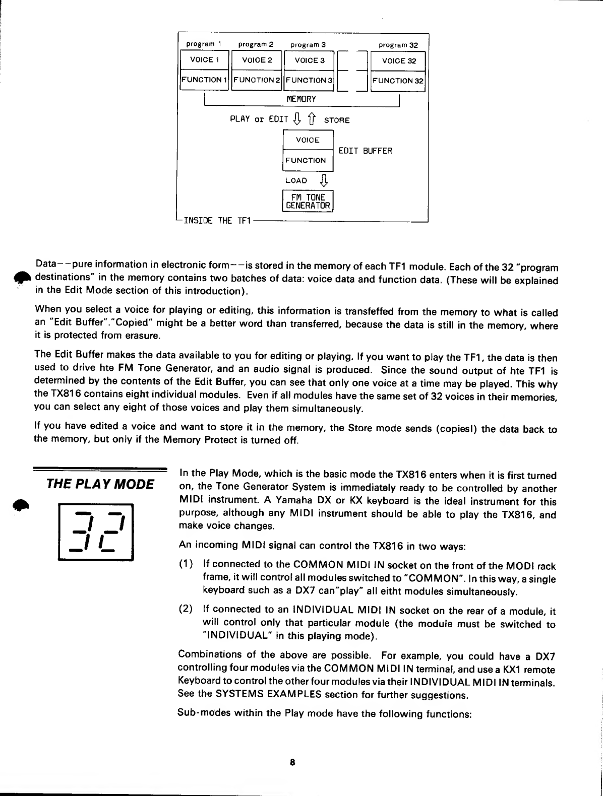
of what goes on inside aTF1 module:

program 1prograrn 2program 3program 32
VOICE 1VOICE 2VOICES VOICE 32
FUNCTION 1FUNCTION 2FUNCTIONS FUNCTION 32
MEMORY
PLAY or EDIT tj" STORE
VOICE
FUNCTION EDIT BUFFER
LOAD
rm TONE
GENERATOR
•-INSIDE THE TF1
Data- -pure information in electronic form—is stored in the memory of each TF1 module. Each of the 32 "program
destinations" in the memory contains two batches of data: voice data and function data. (These will be explained
in the Edit Mode section of this introduction).
When you select avoice for playing or editing, this information is transfeffed from the memory to what Is called
an "Edit Buffer "."Copied" might be abetter word than transferred, because the data is still in the memory, where
it is protected from erasure.
The Edit Buffer makes the data available to you for editing or playing. If you want to play the TF1 ,the data is then
used to drive hte FM Tone Generator, and an audio signal is produced. Since the sound output of hte TF1 is
determined by the contents of the Edit Buffer, you can see that only one voice at atime may be played. This why
the TX81 6contains eight individual modules. Even if all modules have the same set of 32 voices in their memories,
you can select any eight of those voices and play them simultaneously.
If you have edited avoice and want to store it in the memory, the Store mode sends (copiesi) the data back to
the memory, but only if the Memory Protect is turned off.
THE PLAY MODE In the Play Mode, which is the basic mode the TX81 6enters when it is first turned
on, the Tone Generator System is immediately ready to be controlled by another
MIDI instrument. AYamaha DX or KX keyboard is the ideal instrument for this
purpose, although any MIDI instrument should be able to play the TX816, and
make voice changes.
An incoming MIDI signal can control the TX816 in two ways:
(1)
(2)
If connected to the COMMON MIDI IN socket on the front of the MODI rack
frame, it will control all modules switched to "COMMON". In this way, asingle
keyboard such as a DX7 can"play" all eitht modules simultaneously.
If connected to an INDIVIDUAL MIDI IN socket on the rear of amodule, it
wilt control only that particular module (the module must be switched to
"INDIVIDUAL" in this playing mode).
Combinations of the above are possible. For example, you could have aDX7
controlling four modules via the COMMON MIDI IN terminal, and use aKX1 remote
Keyboard to control the other four modules via their INDlVI DUAL MID11Nterminals.
See the SYSTEMS EXAMPLES section for further suggestions.
Sub- modes within the Play mode have the following functions:
8

(a) SET RECEIVE BASIC CHANNEL:
Select Which channel MIDI information is received on. This must be the same as
the channel on which your M!DI instrument is transmitting data. NOTE: MIDI in-
formation may be sent down asingle cable on up to 16 differebnt channels. See
HOW THE MIDI SYSTEM WORKS later in this manual.
(b) SET OMNI ON/OFF:
When the Omni mide is turned on, the module can receive MIDI data on all MIDI
channels.
(c) TUNE MASTER PITCH:
The pitch okf each module may be altered by+/- 75 cents. Tunning each module
to aslightly different pitch makes for amore realistic acoustic sound- -a "natural
chorus" effect.
All Yamaha MIDI instrument can extensively program each other through the use
of inbuilt "system exclusive information" that other manufacturer's MIDI devices
cannot receive. With the TX81 6, you can edit any of the 32 voices stored in each
module, using aDX7, just as if it were an internal voice of the DX7. You can also
edit with aDX1 ,and the smaller DX9 can be used for editing, with some limitations,
as its FM Tone Generation System is slightly less sophisticated than the DX7 (in
technical terms, it has only four operators per voice as compared to six in the DX7).
There are basically two types of data that can be edited:
(1 )Voice Data (145 separate parameters). This is the data that actually creates
the sound of an FM voice: the frequency, level, and envelope characteristics
of each of the six operators; the keyboard level scaling and keyboard rate
scaling settings, and so on. This data is edited using aDX keyboard. The
parameters are listed in Table 4-1 in the MIDI FORMAT chapter, and they
are explained in full in the DX owner's manual.
(2) Function Data (25 speparate parameters) .This applies to parameters that affect
the overall performance of a voice, regardless of tis timbre. These include
poly/mono selection, pitch bend, portamento, glissando, modulation wheel,
foot control, breath control, and after touch, and they are all edited with a
DX keyboard, except for the functions described in palragraph (c) below,
which may only be edited using the front panel controls on each TF1 voice
module.
Sub-modes within the Edit mode have the following functions:
(a) SELECT PROGRAM NUMBER FOR EDIT:
Choose which voice you wish to edit. In this sub- mode the voice may be selected
either by using the front pane! switches on the TF1 ,or by pressing the voice select
keys on aDX7.
(b) ATTENUATE OUTPUT LEVEL:
Adjust the output level of an individual voice. FM digital voices, with their limitless
range of timbres, can vary in level. With this function you can match up levels of
different voices-- rlicularly useful if you wich to change voices during aper-
formance.
(c) LIMIT LOWEST KEYILIMIT HIGHEST KEY:
These two functions allow you to allocate each voice to any part of your DX7 or
MIDI keyboard. You can simply split the keyboard into two halves; divide it into
THE EDIT MODE
9

eight separate sections, each with adifferent voice; or overlap voices in any
combination.
This provides access to the TF1 's internal memory. You can store newly edited
voices, or just their function data, in any of the 32 program destinations In the
memory, with permanent storage guaranteed by the back-up battery (actually re-
quires replacing after about 5years). Before storing data, the Memory Protect must
be switched off. After storing data, the Memory Protect should always be switched
on again.
Sub-modes within the Store mode have the following functions:
(a) SELECT DESTINATION:
Select the program destination in which you wish to store anewly edited voice.
In this way you can arrance the 32 voices in the TF1 to exactly suit your performing
requirements.
THE STORE MODE
(b) STORE VOICE AND FUNCTION:
Having selected adestination for your new voice and its accompanying function
data, this allows you to store this information in the internal memory.
(c) STORE ONLY FUNCTION:
You can also choose to store only the function data In aselected program desti-
nation, without affecting the voice data stored there. This is useful if you want
to rapidly change the function data of several voices; for example, giving agroup
of voices the same portamento setting.
^^^^'^^^=^=^'^=^^= As the name suggests, the Utility mode allows you carry out various data- handling
THE UTILITY MODE jobs, rather than create new data.
Sub-modes within the Utility mode have the following functions:
(a) DAMP ALL VOICES AND FUNCTIONS:
All of the voice and function data may be dumped (output) at one time through
the MIDI OUT terminal on the MIDI rack frame. This could be used for transferring
data from one TF1 module to another. If you dump data into the internal memory
of aDX7 (in this case, voice data only will be received) it can be stored In aRAM
(Random Access Memory) cartridge, so that you can then create new voices In
the TX816. You can also dump voice data onto the floppy disk in aQX1. In this
way, you can easily and inexpensively build up alibrary of voices that will expand
as your musical requirements grow.
(b) CLEAR AND INTIALIZE ALL FUNCTIONS:
Reduce all functions stored in the memory to their original setting i.e., the value
they are set at before leaving the Yamaha factory. Each module is factory pro-
grammed with the same voice set as the DX7. In the TX81 6and TX21 6, however,
appropriate function data is also factory programmed for each voice. Atable In
the UTILITY MODE chapter lists these functions and their Initial values. You could
use this feature after you have dumped all the function data from amodule, and
wish to initialize everything prior to creating anew set of voices.
(c) AUDIO CHECK:
An audio check feature that provides astandard 440 Hz sine wave tone at -4 dBm.
Useful for checking system connections and modules, and setting levels on your
mixer or tapedeck.
//r
uI
10

(d) READ OUT CURRENT VOLTAGE OF BATTERY:
This allows you to make instant checks on the level of the Lithium battery which
acts as aback-up for the data memory of the TX816. The battery has anormal life
of about five years, and should be changed when its level falls below 2.3. volts.
This shows as "23" on the LED.
Now let's see about setting up the TX816 and playing...
11

PRECAUTIONS
NOTE:
Read this section throughly before setting up your TX816. This unit uses
state-of-the-art computer technology which, though outstandingly durable
and reliable, requires certain working conditions in order to carry our its so-
phisticated functions efficiently and accurately.
Avoid placing the TX816 in direct sunlight. Any extremes of temperatures should
LOCATION also be avoided, as they can cause errors in data storage and transmission. The
microcomputer circuitry employed in the TF1 FM tone generating module is de-
signed to function best within a"normal" temperature range. If you are using your
TX816 in temperatures over 40 deg.C (for example, at an outdoor concert in ahot
climate) it is recommended that you use acooling fan to keep it at alower tem-
perature.
Extremely high humidity or dry conditions shiuld be avoided, as should excessive
dust or vibrations. The TX816 performs as efficiently onstage as it does in a
studio- -provided you treat it as you would afine automobile- -with care and
caution.
Ensure that the ventilation grills on the upper and lower surface of the TX816 are
uncovered so that air may circulate freely to eliminate any risk of overheating.
It's also advicable to set the TX81 6at aconvenient height for you to operate. You
should be easily able to reach the switches on the front panel, as these may be
used constantly during an editing session. You should also ensure that you can
get agood front-on view of the LED indicator on the front panel of each TF1. If
you look at them from too great an angle, you may miss parts of the LED Display.
If you intend to experiment with different MIDI connection configurations (this
can be highly creative and rewarding) you will also require easy access to the rear
of the unit, as it is preferable not to move the unit while it is switched on.
The MIDI rack frame is built to the internationally standard 19" (480mm) width,
so for permanent installation your TX81 6may easily be rack mounted in astudio.
To remove dirt or fingermarks from the exterior paneling of the TX816 it is best to
use asoft, dry cloth that will not shed any fluff. It is not advisable to use any solvents
such as benzine or thinners. Do not use any aerosol sprays near this unit- -they
can get into the circuitry and prevent accurate storage and transmission of data.
CLEANING THE
EXTERIOR
PANELING
The TX816 contains innumerable innumerable digital circuits. It may cause static
EFFECTS ON OTHER interference with radios or televisions in close proximity. It is advised that you keep
ELECTRICAL these types of equipment as far away from the TX81 6as is coknveniently possible.
EQUIPMENT
12

The TX816 consumes 7iO watts of power. The TX216 consumes 20 watts. Their
POWER SUPPLY voltage rating is as follows:
U.S. and Canadian models: 120 V(50/60 Hz).
General model: 100-120/220-240 V(50/60 Hz) Voltage selector incorporated.
Ensure that the correct voltage is selected if you have tha general model, if you
are not going to use the TX816 for afew days or more, it is advisable to unplug
it from the AC power supply. It is also wise to unplug it during
Thunderstorms, as power surges caused by lighting may affect stored data.
^^^^^='^^'==== Anumber of error displays are built into each TF1 to let you know if any internal
ERROR DISPLAYS problems are occurring. The red Error LED will light, and anumber will appear in
the LED Display to inform you of the type of problem. You can cancel the error
display by pressing any of the three keys on the front of the module. The following
chart lists the ten types of errors, and how to deal with them.
LED
DISPLAY ERROR REMEDY
1Data Receive Error Indicates that data has not
been properly received.
Adjust thedata at the sourst
and transmit data again
2Receive Buffer Full
3Bulk Data Check
sum error
4Low Battery Level Replace Battery
5ROM Hardware Error These errors are all
caused by afault in
the internal circuitry
the TF1, and you will
need to c|ontact your
nearest yamaha dealer
6RAMI Hardware Error
7RAM2 Hardware Error
8RAMS Hardware Error
9RAM4 Hardware Error
10 Trap Error
'Keep the Owner's Manual in asafe place. Even though you may have become totally
KEEP THIS MANUAL familiar with the TX81 6, tuture reference to the manual may will prove to be highly
informative.
^^====!='===^= If you possess aYamaha DX7 synthesizer or KX1 remote keyboard that was ma-
IF YOU ARE USING nufactured before MIDI Version 1,0 was finalized, you may find that the after-touch
QX7 OR KXI ^^^^ function when using one of these keyboards to control the TX81 6. In this
case, contact the store where you purchased your keyboard and ask them to replace
the ROM system. Models with the following serial numbers will require this update
modification:
DX7: Serial Nos. 1001 —24880, 25125—26005.
KX1: Serial Nos. 1001 --11 05.
13

CONVENTIONS
The following simple conventions are used to make this manual easier and quicker to read.
1. The switches on the front panel of each voice module are multi-purpose switches which will be referred to
in the text simply as SW1, SW2 and SW3 (reading from top to bottom of the panel). The FRONT PANEL
FEATURES section explains the functions of these switches.
LED*
5liJ2
LED DISPLAY SU3
TF1 -FRONT
2. All these switches may be used in two different ways: (a) by pressing and retasing immediately, to change
data in single increaments (pressing and relasing SW3 will switch the module from one SUB- MODE to another
SUB- MODE): (b) holding down aswitch, to change data continuously and rapidly until the key is relased
(holding down SW3 for longer than two seconds will switch the module from one MODE to another MODE).
in the text, then, the words "press" and "hold down" will always be used to indicate these two different actions.
3. The MIDI terminals on the front panel of the MIDI rack frame are referred to as "COMMON" as they provide
access to all modules. ("COMMON" is not always applied to the MIDI OUT terminal as it is the only MIDI
OUT TERNINAL on the TX81 6).
IvflDI RACK
14

4. The MIDI terminals on the rear of each voice module are referrd to as "INDIVIDUAL" as they provide access
only to the module In which they are installed.
"IIMDIUIDUAL
TF1 -REAR
5. The indicators on the fornt panel of each module are of two basic types: LED's (small coloured lights) of
which there are five; and the LED Display (an indicator that displays one or two digits or tetters, simitar to some
watches or calculators). The words "LED" and "LED" Display" will be used to differentiate between these two
types of indicators.
6. Wherever the LED Display is illustrated in the text, we wilt use the following conventions:
Program number: 32* unless another number is required.
Flashing display:
Alternating display: [^r~h*(j7?]
*In the case of variable numerical data, such as program number, note limit, MIDI channel number, tuning setting,
etc., the examples given in the text may not necessarily conform with the numerical LED Display you see when
you operate the TX816. The full numerical data range of each function will be mentioned in the text.
15

SETTING UP
Please read the PRECAUTIONS section before setting up your TX816. The TX816 is not acomplicated unit to
use, but it requires certain optimum working conditions andj although highly reliable, it should be treatead with
awareness and care.
Make all audio and MIDI connections before connecting the equipment to the AC supply. Do not apply and
unnecessary force to switches or terminals.
Always remove cables by grasping the plug, not by tughging on the cable, otherwise damage may occur.
The FM digital voices created by the TX816 are rich, complex, and exceptionally pure and distortion-free. We re-
commend that you use high quality amplifiers and speakers with full frequency response, to get full enjoyment
of this extraordinarily powerful device.
THE BASIC SYSTEM
-w
AUDIO OUT 1—8(TO MIXER)
fItfft ff
YAMAHA
MIDI HACK
I'd
MIDI
IN
:.^:-..n-:
mu w
on mu
y'MIDI
OUT
1
1AUDIO OUT
TO MIXER
(OPTIONAL)
DX7
mMIDI
OUT
YAMAHA CSX^ [jjOOO oooo
uMIOI
'in I
4-
To illustrate most of the modes and functions on the TX816, we will assume,
throughout this manual, abasic system comprised of the TX816 with aDX7 key-
board. If any other equipment is needed to demonstrate certain functions, or if there
are any special instructions needed if you are using aTX21 6, this will be explained
in the text Prior to actually setting up this system, please read this entire SETTING
UP chapter, if you are not using aDX keyboard, but are linking alternative MIDI
control devices to the TX816, this chapter will still contain much vital information.
16

For the basic system you will require:
*AYamaha TX816 FM Tone Generator System.
*AYamaha DX7 Programmable Algorithm Synthesizer.
*A high quality eight channel mixing console, with at least eight input channels.
(An amplifier with two inputs would be sufficient for the TX216, as it only has
two audio outputs).
The audio output on each TF1 module has an impedance of 600 ohms and is rated
at -lOdBm.
*Ahigh quality power amp/speaker system. Stereo is preferable, for full enjoyment
of the TX81 6's sight voices.
*Two standard MIDI cables.
*Eight balanced line audio cables with XLR type connections. (For the TX21 6, two
cables are sufficient).
^==============^^^^^^= The TX816 receives highly complex information via MIDI cables, so only MIDI
MIDI CONNECTIONS standard DIN cables should be used, like the ones that are supplied with the TX81 6.
If you wish to purchase further MIDI cables, we recommend the Yamaha MIDI-03
and MIDI -1 5cables (3 metres and 15metres long respectively). MIDI cables longer
than 15 meters should not be used, as the MIDI signal can deteriarate if sent over
too long adistance, and data errors may result.
(a) Make sure that the TX81 6and the DX7 are not connected to the AC supply.
Connect the MIDI OUT of the DX7 to the COMMON MIDI IN on the front
of the TX816 MIDI rack frame. This enables the DX7 to send MIDI data to
the TX816, and "play" the eight voice modules.
(b) Connect the MIDI IN of the DX7 to the COMMON MIDI OUT on the front
of the TX816. This enables the TX816 to dump voice data into the DX7's
internal memory.
Each TF1 module in the TX816 has abalancaed line XLR type output on its rear
panel. This connector is wired in the following manner: Pin 1:Shield: pin 2: Hot:
pin 3cold. FM digitally generated voices are subtle and complex, and we recommend
that you use the highest quality of cables abailable to connect your TX81 6audio
outputs to your mixer,amplifier or tape deck.
(a) Make sure that the TX81 6and your mixer are not connected to the AC mains.
Connect the eitht audio aouputs on the back of the TX816 to eight line inputs
on your mixer (the inputs must be suitable for a600 ohm signal rated at -10
dBm). The easiest method is to connect outputs 1thru 8of the TX816 to
input channels 1thru 8on your mixer. You can adjust input channel sensitivity
using the audio Check Signal, as described later in this chapter.
(b) As an option, you can connect hte audio output of the DX7 to your mixer if
you with. This will give you atotal of nine voices which can be played si-
multaneously. However, to hear more clearly how the DX7 controls the TX81 6,
it is better not to use this option to begin with. NOTE: The volume control
lever on the DX7 will not affect the volume of the TX816 voices.
AUDIO
CONNECTIONS
17

Once you have made all your MIDI and audio connections, you can now connect
all your equipment to the AC mains supply. The poser requirements of the TX816
and TX216 are as follows:
U.S./Canadian models: 120V (50/60 Hz). General model: 110-120/220-240 V
(50/60 Hz)> Voltage selector incorporated.
Ensure that the voltage selectors is seitched to the correct setting for your area, if
you have tha general model.
Once this is done, turn on your equipment in the following sequence:
(a) Turn on your DX7 first. NOTE: if you switch on the DX7 after turning on the
TX81 6, the ERROR LED on the front of any of the TF1 modules switched to
"COMMON" will light, and the LED Display will show a"1". You will now
have to press any of the three switches on the fornt of the module, to reset
it.
(b) Turn on the TX816 by pressing the power switch on the fornt of the MIDI
rack frame. Ail of the LEDs on the front panel wilt light up, and then after
about two secontd there will be an audible click and aprogram number (voice
number) will appear in the LED Display on each module, indicating that they
are now in the Play mode and ready to use. At the same time, some of the
other LEDs will go out.
Each module should now have 3LEDs lit: the LED Display (a number); the Memory
Protect LED (the Memory Protect function is always turned on when you turn the
tX81 6power on, even if it was turned off the last time the unit was used);and either
the INDIVIDUAL or COMMON LED.
(c) Turn on your mixer and power amp/speaker system.
You can now set your mixer input sensitivities using the TX816's built-in AUDIO
CHECK. This is done for each individual TF1 module, using the following procedure:
(a) Hold SW3 (the SELEDT key) until you see the [S3 display, then immediately
release the key. This will take about 4second, and will be preceded by the
\Ed\ and [SQ displays. The TX816 is now in the Utility mode, if you held
SW3 down too long and have "gone past" this mode, keep holding SW3 down
until you see the correct display.
(b) Select the AUDIO CHECK SIGNAL sub-mode by briefly pressing SW3 three
times. You should now see the alternating LED Display [r~]"**rT1 .This
shows that the AUDIO CHECK SIGNAL is ready to be activated, if you have
"gone past" this sub- mode by pressing SW3 too many times, press SW3 re-
peatedly until you see the correct display.
(c) Set the input channel sensitivity on your mixer to its minimum, then turn on
the AUDIO CHECK SIGNAL by pressing SW1. The LED Display will now
show [i h-*r^
The TX816 wilt now be producing astandard 440 Hz tone at -4dBm, and you can
adjust the input sensitivity on your mixing console to match this.
(d) Once you have adjusted your input sensitivity, you can go straight back to
the Play mode by holding down SW3 until you see the program number in
the LED Display.
(e) Now repeat the same procedure (paragraphs (a) to (d) above) for the other
seven TF1 modules. (In the case of the TX216, of course, there is only one
more module to check, after which you can continue on to the next section).
18

You can now play the preset voices in the TX816 form your DX7. Here's how it's
BASIC OPERATIONS done:
(a) Switch all modules to "COMMON", by pressing SW1 .The COMMON LED's
will light on each module.
(b) You will now find that, as you press the voice selector keys on the DX7, all
eight modules on the TX81 6will switch to the same program numbers, which
will be indicated on all their LEO Displays. You can now play all eight modules
simultaneously from your DX7. Switch form one set of eight voices to another,
and enjoy the different combinations that are available to you at the touch
of aDX7 voice select key.
And now, here's how you can change the voices of individual modules, and create
different combinations of eight voices.
(c) Switch all of the modules except one to "INDIVIDUAL". You can now play
only the one that is left in the "COMMON" mode. Set this one to adesired
voice by selecting avoice on the DX7. Then switch the module to "INDI-
VIDUAL. With all modules in "INDIVIDUAL", no sound will come from the
TX816 when you paly the DX7.
(d) Switch another module to "COMMON" and select another voice. Then swicth
it back to "INDIVIDUAL". Continue through the eight modules in the same
manner, setting each one to adefferent voice.
(e) And now--the moment of truth! switch all modules to "COMMON" and
play the DX7, You wilt hear your personally selected combination of eight
voices—an impressive sound which will be even more magnificent if you
have arranged the eight voices in astereo pattern (one good way is to have
voice 1on the left, voice 8on the right, and the other voices spread out between
them).
You'll notice that the orange "COMMON" LEDs on the TX816 are flashing while
you play. This shows that MIDI data is being received by the TX816: data that
indicates "Key On" when you hit akey, "Key Off" when you release akey, and "Pitch
Bend", "Modulation Wheer'/'Sustain Footswitch", "After Touch" and so on when
you use the various functions.
(f) Here's how you can make it sound even more impressive: by slightly detuning
each module. Start with module 1. Select the TUNE MASTER PITCH sub-
mode by pressing SW3 briefly three times. The LED Display will show
dot indicating minus number
This example indicates that you are in the TUNE mode and that the tuning is set
at minus two (minus mumbers are indicated by adot in the upper left corner of
the LED Display). The tuning setting can vary from -64 to +63.
(g) Set the tunig to zero, by pressing either SW1 or Sw2, to increase or decrease
the pitch number. Pressing either of these switches wilt add or subtract one
from the pitch number. Holding aswitch down will rapidly and continuously
change the tuning.
19
Other manuals for TX816
3
This manual suits for next models
1
Table of contents
Other Yamaha Synthesizer manuals

Yamaha
Yamaha FB-01/U User manual

Yamaha
Yamaha DX21 User manual

Yamaha
Yamaha DX9 User manual

Yamaha
Yamaha Portatone PSR-S700 User manual

Yamaha
Yamaha VL7 User manual

Yamaha
Yamaha YS200 User manual

Yamaha
Yamaha SY99 User manual

Yamaha
Yamaha CS6X User manual

Yamaha
Yamaha DX1 User manual

Yamaha
Yamaha VL-1 User manual

Yamaha
Yamaha pf10 User manual

Yamaha
Yamaha pf10 User manual

Yamaha
Yamaha Sonogenic SHS-500 User manual

Yamaha
Yamaha SY99 User manual

Yamaha
Yamaha W5 User manual

Yamaha
Yamaha P-60 User manual

Yamaha
Yamaha EX5 User manual

Yamaha
Yamaha P-70 User manual

Yamaha
Yamaha CS-15 User manual

Yamaha
Yamaha DX27 User manual