Yamato CA801 User manual

Cold Trap
CA801
Instruction Manual
First Edition
●Thank you very much for purchasing this Yamato
Cold Trap CA801.
●Please read the “Operating Instructions” and
“Warranty” before operating this unit to assure proper
operation. After reading these documents, be sure to
store them securely together with the “Warranty” at a
handy place for future reference.
Warning:
Before operating the unit, be sure to read
carefully and fully understand important
warnings in the operating instructions.
Yamato Scientific America Inc.
Santa Clara,CA
Instructions are printed on recycled paper.


Contents
1. Safety precautions........................................................................................................................... 1
Explanation of pictograms.................................................................................................................. 1
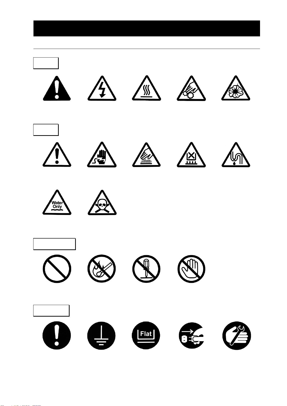
List of symbols ................................................................................................................................... 2
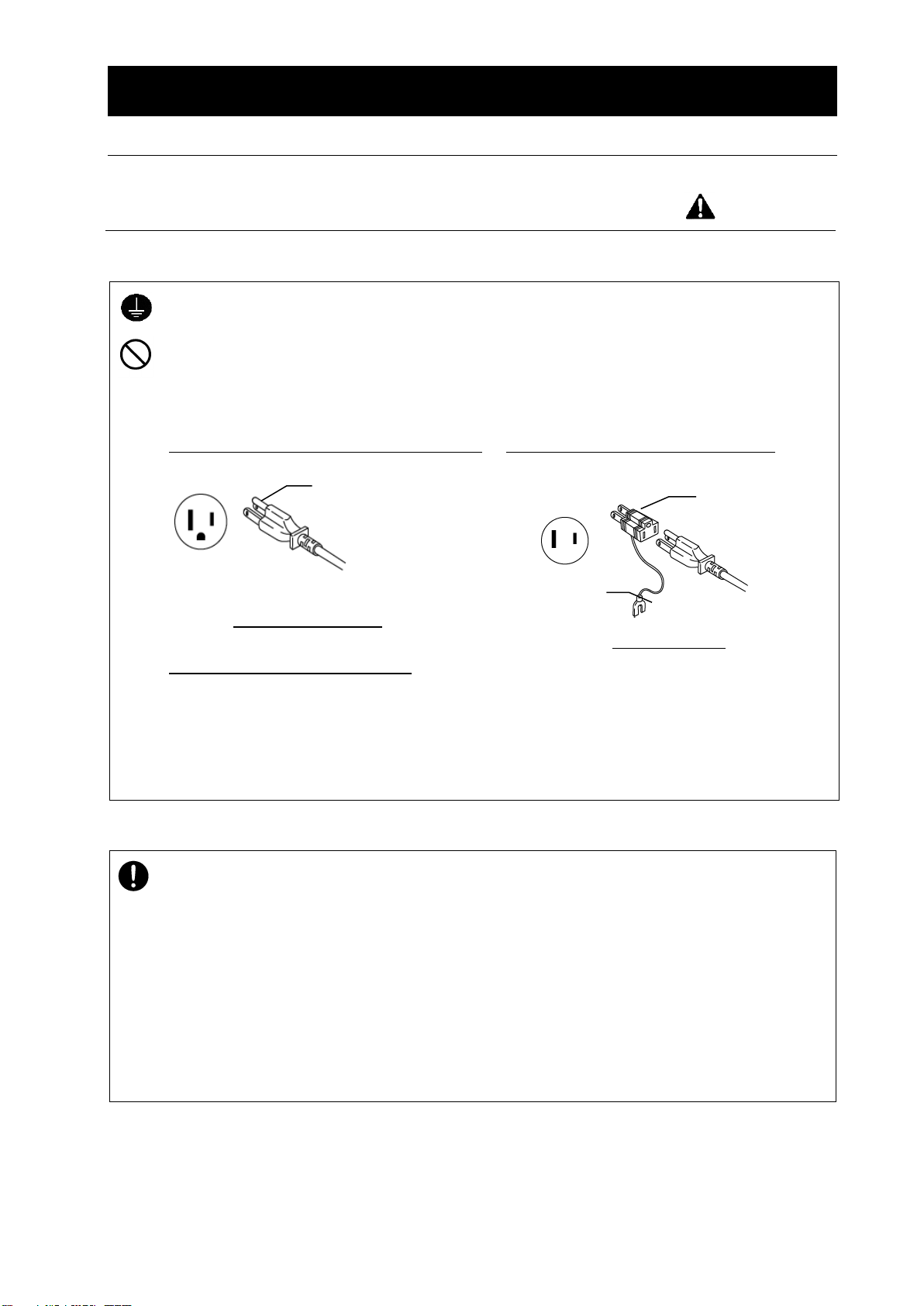
Warnings & Cautions.......................................................................................................................... 3
2. Before operating the unit................................................................................................................ 5
Cautions for installation...................................................................................................................... 5
Installation procedures/precautions ................................................................................................... 9
3. Name and Functions of each Part................................................................................................ 10
Main body......................................................................................................................................... 10
Details of each part ...........................................................................................................................11
4. Operation Method.......................................................................................................................... 12
Operation method ............................................................................................................................ 12
Operation method ............................................................................................................................ 13
Cooling Curve(Reference data)................................................................................................... 14
5. Cautions for Handling................................................................................................................... 15
6. Maintenance................................................................................................................................... 17
Daily inspection/maintenance .......................................................................................................... 17
7. When the unit is not to be used for a long time or when disposing......................................... 18
When the unit is not to be used for a long time or when disposing.................................................. 18
Requests in case of disposal ........................................................................................................... 18
8.Troubleshooting Guide .................................................................................................................. 19
Check list.......................................................................................................................................... 19
9. After sales service and warranty.................................................................................................. 20
When requesting a repair................................................................................................................. 20
10.Specifications ............................................................................................................................... 21
11.Connection Diagram..................................................................................................................... 22
Connection diagram......................................................................................................................... 22
12. Replacement Parts List............................................................................................................... 23
13. List of dangerous materials........................................................................................................ 24
14. Standard installation manual...................................................................................................... 25

1
1. Safety precautions
Explanation of pictograms
About pictograms
A variety of pictograms are indicated in this operating instruction and on
products for safe operation. Possible results from improper operation
ignoring them are as follows.
Be sure to fully understand the descriptions below before proceeding to the
text.
Warning
Caution
Indicates a situation which may result in minor injury (Note 2) and
property damages (Note 3.)
(Note 1)Serious injury means a wound, an electrical shock, a bone fracture or intoxication that may
leave after effects or require hospitalization or outpatient visits for a long time.
(Note 2)Minor injury means a wound or an electrical shock that does not require hospitalization or
outpatient visits for a long time.
(Note 3)Property damage means damage to facilities, devices and buildings or other properties.
Meanings of pictograms
This pictogram indicates a matter that encourages the user to adhere to warning
(“caution”included).
Specific description of warning is indicated near this pictogram.
This pictogram indicates prohibitions
Specific prohibition is indicated near this pictogram.
This pictogram indicates matters that the user must perform
Specific instruction is indicated near this pictogram.
Indicates a situation which may result in death or serious injury (Note 1.)

2
1.Safety precautions
List of symbols
Warning
General warnings
Danger!: High
voltage
Danger!: High
temperature
Danger!: Moving
part
Danger!: Hazard
of explosion
Caution
General cautions
Electrical shock!
Burning!
Caution for no
liquid heating!
Caution for water
leak!
For water only
Poisonous
material
Prohibitions
General bans
Fire ban
Do not
disassemble
Do not touch
Compulsions
General
compulsions
Connect ground
wire
Install levelly
Pulloutthepower
plug
Regular
inspection

3
1.Safety precautions
Warnings & Cautions
Warning
Never operate the unit in an atmosphere containing flammable or explosive gas
Never operate the unit in an atmosphere containing flammable or explosive gas.
Otherwise, an explosion or a fire may result since the unit is not explosion-proof.
See section “13. List of dangerous materials” on page 24.
Be sure to connect the ground wire.
Be sure to connect the ground wire correctly. Otherwise, electrical leak may result and cause an
electrical shock or a fire.
Ban on operation when an abnormality occurs
When a smoke or an unusual odor is seen or sensed, immediately turn the ELB on the main unit
off and pull out the power plug.A fire or an electrical shock may result.
Never use electrical power cords bundled.
When these are used bundled, they might overheat causing a fire.
Take care not to damage electrical power cords.
Avoid tightly bend, pull with a strong force or twist to prevent electrical power cords from
damaging.A fire or an electrical shock may result.
Ensure sufficient ventilation when using flammable and combustible solutions.
If left at the room temperature (or below for certain solutions), flammable and combustible solutions
(ethanol, etc.) may be vaporized and thus ignited and exploded by any ignition source (switch, etc.).
Never try to disassemble or alter the unit.
Never try to disassemble or alter the unit.A malfunction, a fire or an electrical shock may result.
Do not place the unit on its side.
Never place the unit on its side during transfer/transport because the refrigerator may suffer failure.
If the unit is to be tilted toward its side temporarily during carry-in, do not turn ON power supply for at
least one day (24 hours) after completion of carry-in.

4
1.Safety precautions
Warnings & Cautions
Warning
When a thunder is heard.
When a thunder is heard, turn the main power off immediately. A malfunction, fire or an electrical
shock may result.
Keep hands away from the condensate and wall surface of the trap tank.
Condensate and wall surface of the trap tank becomes cold during operation and for a certain period
of time after operation. If you touch it, you will suffer frost bite. Never touch the condensate.
Do not touch the condenser fin with bare hands.
Never touch the condenser fin with bare hands during maintenance. The fin has sharp edge and
may cut hands.

5
2. Before operating the unit
Cautions for installation
Warning
1. Take care to select an appropriate installation site.
Avoid installing the unit, above all, in places listed below:
・Uneven or dirty floor
・Where floor is not level.
・Where temperature may
change widely.
・Where humidity is high.
・Where subject to direct
sunlight.
・Place with unstable power
supply.
・Where flammable gas or corrosive gas may exists.
・Where environmental temperature is 5℃or less or
30℃or over.
・Not well-ventilated place.
・Where vibrations are severe.
・Outdoor
Install this unit at a place with spaces shown below.
40cm or more
(Rear)
20cm or more
20cm or more
Front
Main Body
2. Installation
The unit might fall down or move by an earthquake or an impact resulting a personal injury.
We recommend making safety measures such as to avoid installing the unit at a place other
than busy places. This trap incorporates an air-cooling refrigerator, which produces waste
heat. Use the trap in a well-ventilated or air conditioned place to prevent rising of the ambient
temperature. Higher ambient temperature causes drop of operation efficiency. Moreover,
the refrigerator is put into high-temperature high-pressure operation, resulting in failure.
3. Never operate the unit in an atmosphere containing flammable or explosive
gas.
Never operate the unit in the flammable or combustible gas atmosphere. This unit is not of
an explosion-proof structure,and ON/OFF switching and operation may cause arc, resulting
in explosion and fire.
For flammable and explosive gas, refer to “13. List of Hazardous Materials” in page 24.
爆発性ガス
可燃性ガス
Explosive gas
Flammable gas

6
2. Before operating the unit
Precautions when installing the unit
Warning
4. Never attempt modification.
5. Install the unit on a level surface.
Never attempt modification by the
customer so as to prevent failure.
Install the unit on a level surface.
Accidental trouble or failure may occur unless
the product is installed a level surface.
The product weighs about 65 kg. When
lifting the unit for transportation and
installation, carefully handle it by at least
two people.
6. Secure sufficient ventilation for the unit.
Do not operate the unit when its front/side panels and vent holes are blocked.
Internal temperature of the unit will rise degrading the performance and an accident, a
malfunction or a fire may result.
7. Do not operate the unit at such a place that may subject to splash.
Do not operate the unit at such a place that may subject to splash. Liquid entering the inside
may cause an accident, a malfunction, an electrical shock or a fire.
Modification

7
2. Before operating the unit
Precautions when installing the unit
Warning
8. Be sure to connect the earth wire.
・Be sure to connect the earth wire (green wire of the power cord) to the earth wire or to
the earth terminal.
・Never connect the earth wire to the gas pipe or water pipe, in order to prevent fire.
・The earth wire must never be used for grounding of the telephone line and lightning
arrestor. This is to prevent fire and electric shock.
・Never use the branch socket outlet because it causes hazardous heat generation.
Used of ground socket outlet recommended
Ground socket outlet
When there is no ground terminal.
●In this case, class D grounding work is
necessary and please consult your dealer or
our customer service center.
When a bipolar type outlet tap is used
Ground adaptor
●Insert the ground adaptor included as an
option, into a power plug confirming the polarity
of the outlet. Connect the grounding wire
(green) of the ground adaptor to the ground
terminal on the power supply equipment.
9. Use a dedicated outlet for the power supply.
Use a power supply that meets the electrical capacity of the unit.
Electrical capacity::AC115V±5%50/60Hz 6A
When the unit will not start even when you turn the power switch to “ON”, check for low main
voltage or if the unit is connected to the same power supply line as other devices and
connect it to another line if necessary. Avoid using wire extensions using a cord reel, which
may result in degradation of freezing capacity or stoppage of refrigerator from possible
voltage drops. Do not connect too many wires to a single outlet using a branching adaptor.
Otherwise, a fire or an electric shock may result.
Dipole 115V power
Earth adaptor
Three pole power plug
with earth pole
Earth wire
W
w
G
Earth pole
Three pole power plug with
earth pole

8
2. Before operating the unit
Precautions when installing the unit
Warning
10. About handling of power cords
・Never use electrical power cords bundled. When these are used bundled, they might
overheat causing a fire.
・Do not convert, forcibly bend, twist or pull the power cord. Otherwise, a fire or an
electrical shock may result.
・Do not place the power cord under a desk or a chair, or sand between objects to avoid it
from being damaged.
Otherwise, a fire or an electrical shock may result.
・Do not place the power cord close to a stove or other heat generating device. Sheath of
the cord may burn and result in a fire or an electrical shock.
・If the power cord should be damaged (exposure of core wire or disconnection),
immediately turn the power switch of the main body off, pull off the power plug and ask
your dealer to replace the cord. If the unit is operated with a damaged power cord, a
fire or an electrical shock may result.
・Connect the power cord to an appropriate wall outlet.

9
2. Before operating the unit
Installation procedures/precautions
(1) Release the stopper lock of the caster
wheels.
Set the stoppers of the caster wheels to
the high position as shown in the drawing
in the right.
Now the lock is released.
(Only two caster wheels at the front of
the unit have stoppers.)
(2) Transport the unit to the installation place
※Transporting the unit over a gap may
give an excessive shock to the
caster wheels and may damage
them.
If such trouble is expected, lift the
unit and transport it over the gap.
※When lifting, never allow the product
to tilt or lay on its side.
(3) When the installation place has been
determined, lock the product by pressing
down the caster stopper lever and set the
caster fixing holders (accessories) under
the casters.
(4) Check the drain plug.
※Confirm that the drain plug has not
been removed.
(5) Connect the power plug
Confirm that the power switch (earth leakage
breaker) is OFF and the refrigerator switch is OFF.
Connect the power plug to the socket outlet.
Drain hose
Drain plug
Caster
Unlocked
Locked
Stopper
Caster fixing holders

10
3. Name and Functions of each Part
Main body
Front view
Back view
Cover with nozzle
Power cord
(with plug)
Caster
(Only front two casters are
provided with stopper)
Power switch (earth
leakage breaker)
Operation panel
Air vent dust-proof
filter
Rating nameplate/serial
No. nameplate
Drain hose
Trap tank
Fixing knurled screw x 2

11
3. Name and Functions of each Part
Details of each part
Operation panel
No
Nomenclature
Control/operation
①
Refrigerator switch
Starts/stops tank inside cooling operation by the refrigerator.
※The protective delay timer allows operation start in three
minutes after the switch ON.
※Used also for stop of defrosting halfway of operation.
②
Defrost switch
Starts defrosting operation.
This is to melt ice adhering to the inside wall surface of the trap tank.
※Effective when the refrigerator switch is ON.
③
Error lamp
ON in case of overload to the refrigerator or disconnection of the
temperature sensor.
④
Temperature
indicator
Indicates the temperature of the inside wall of the cooling trap tank.
※This controller is used as the temperature indicator. The
indicated temperature is used as a guideline.
※Key operation is invalid and cannot be made.
Cover with nozzle
No.
Nomenclature
Control/operation
⑤
IN side
Connect to the vacuum equipment.
⑥
OUT side
Connect to the vacuum pump.
④
③
①
Used as temperature
indicators. No key
operation
Error Defrost Refrigerator
②
⑤
⑥

12
4. Operation Method
Operation method
For aqueous liquids to be trapped, take the following procedure.
Acids and organic solvents, if used, may cause corrosion and rust. Use an optional glass
condenser.
For the connection method, refer to the manual attached to the glass condenser set.
1.
Set the lid with nozzle.
①Confirm that the trap packing and the lid with
nozzle are free from adhesion of any dust.
※Damage or dust adhesion, if any, may
deteriorate the degree of vacuum inside
the trap tank.
②Set gently the lid with nozzle on the trap
packing while ensuring that “IN” and “OUT” are
in the correct direction.
③Turn the cover with nozzles till it is caught by
the knurled screw. Turn the knurled screw till
the cover with nozzles will not move, then fix it
temporarily.
※The cover with nozzles is secured firmly when
vacuuming is made. Excessive tightening of
knurled screw may cause deformation of the
cover and packing. Therefore, tighten
moderately.
2.
Connect the vacuum hose.
Connect the “IN” side of the lid with nozzle to the
vacuum unit and the “OUT” side to the vacuum
pump via the vacuum hose.
※The nozzle of the lid is positioned on the
“IN” side and the “OUT” side respectively.
Take care to avoid wrong connection.
※The vacuum hose is not included in
accessories. Procure the vacuum hose
of 12 mm or 15 mm in inside diameter
separately.
3.
Turn ON the power switch (earth leakage
breaker).
入
Turn ON the power switch (earth leakage breaker)
on the right side. The temperature indicator
shows the current temperature.
4.
Turn ON the refrigerator switch.
The switch lamp goes ON, and the refrigerator
starts operation in three minutes.
※The refrigerator is not started immediately even
if the switch is turned ON. Since the three-minute
delay timer is active for protection of the
refrigerator, the refrigerator starts only after the set
time of the timer.
OUT
IN
Trap packing
IN side (From
vacuum unit)
OUT side (vacuum pump)
Vacuum hose
Knurled screw
Refrigerator

13
4. Operation Method
Operation method
5.
Run the vacuum pump.
When cooling of the trap tank is over, turn ON the
vacuum pump. Vapor generated in the vacuum
system is trapped in the trap tank.
6.
Operation stop
~For recovering liquid~
~For the case of ice accretion~
①Turn OFF the refrigerator switch to stop the
trap.
②Carry out purging of the unit to which the
product is to be connected.
④Turn OFF the vacuum pump.
⑤Remove the drain plug and drain the
condensate completely from the trap tank.
※To prevent oil backflow in the vacuum
pump, return the vacuum pump switch to
the atmospheric pressure once, then turn it
OFF (this is to purge air).
①Carry out purging of the unit to which the
product is to be connected.
②Turn OFF the vacuum pump.
③Defrost icing within the trap. With the
refrigerator switch left at ON, press the defrost
switch. The switch lamp goes ON and
defrosting begins.
※Defrosting stops automatically after
operation for 45 minutes, and the defrost
lamp goes OFF. To interrupt defrosting
halfway of operation, turn OFF the
refrigerator switch to stop operation.
④Remove a plug of drain hose and drain the
condensate completely from the trap.
※Defrosting cannot always remove the ice
totally. Remaining ice must be removed
manually by wearing gloves.
⑤Turn OFF the refrigerator switch after
automatic stop of defrosting.
7.
Turn OFF the power switch (leakage
breaker).
Turn OFF the power switch (leakage breaker) on
the right side.
Caution
●Before operation, be sure to check if the vacuum hose has been connected to the cover with
nozzles.
Refrigerator
Defrost Refrigerator

14
4. Operation Method
Cooling Curve(Reference data)
1. Temperature indicated when there is nothing in the trap (no-load)
2. Temperature indicated when the trap is filled by 2.5L of ethanol (with load)
Caution
●When the optional glass condenser is to be used, filling the trap with ethanol will help improving
the solvent recovery rate. Fill ethanol by the amount of about 2.5 L. Ethanol is highly
inflammable. Always use ethanol in a well-ventilated room and never attempt unmanned
operation.
Time (min.)
Temperature
(℃)
Temperature
(℃)
Time (min.)
Conditions:1001V 50HZ
Room temp.30℃
Room temp.23℃
Conditions:1001V 50HZ
Room temp.23℃

15
5. Cautions for Handling
Warning
1.Handling of flammable and combustible solutions
This product is not of an explosion-proof structure. For samples to be handled with this trap,
specifically, for explosive and combustible substances and any substances containing these
substances. pay particular attention. If left at the room temperature (or below for certain
solutions), flammable and combustible solutions may be vaporized and thus ignited and exploded
by any ignition source (switch, etc.). Ensure sufficient ventilation during operation. (See “13. List of
Hazardous Substances” of P.24.)
2. Ban on use/countermeasures when an error occurs
If smoke is emerges on the unit or an odd odor is felt, immediately turn the ELB on the main
unit off, turn the main power source off and contact your dealer, a Yamato sales office or our
customer service center for inspection. Otherwise, a fire or an electrical shock may result.
The user shall never attempt to repair the unit to avoid any possible dangers.
Caution
1. Maximum trap capacity
The maximum trap capacity for the aqueous system is about 1.0Kg. Filling the trap beyond
this limit may cause clogging of “IN” and “OUT” nozzles.
2. Never climb on the unit.
Never climb on the unit. The unit may topple over or be damaged and a personal injury or a
malfunction may result.
3.Do not place objects on the unit.
Do not place objects on the unit. They may fall and cause a personal injury.
4. When a thunder is heard.
When a thunder is heard, immediately turn the ELB of the main unit and the main power
supply off. Leaving it as it is may cause a fire from lightening.
5.Recovery from power outage
In case of stop of operating unit due to power outage or in case of power recovery, this unit
resets automatically to the state immediately before power outage and resumes operation.
However, in case of power outage during defrosting, the refrigerator is operated after recover
from power outage. Press the defrost button again to resume defrosting.
When resumption of operation after automatic reset is not favorable, turn OFF the power
switch (earth leakage breaker).
6.Carry out thorough cleaning.
This unit has already been cleaned. However, for initial use after purchase or after long-time
shutdown, clean the tank inside and the cover with nozzles thoroughly before use.

16
5. Cautions on handling
Caution
7. During nighttime and when the unit will be left stopped for an extended period.
・Turn the power switch (ELB) to “OFF” and remove the power plug from the receptacle
during nighttime and when the unit will be left stopped for an extended period of time.
・Drain liquid at the drain cock from the circulation system if you are not going to use the unit
for an extended period of time.
8. Supply voltage
The operation voltage must be within ±5%or less of rated voltage.
9. Refrigerator pressure error
When the piping inside pressure becomes high due to overloading to the refrigerator, the
circuit to protect the refrigerator pressure is activated, turning ON the refrigerator error lamp
and shutting down the refrigerator. In this event, turn OFF the breaker immediately and refer
to 8. Troubleshooting in page 19.
10. Refrigerator overload relay
Operation of the refrigerator in the high temperature range may activate the refrigerator
overload relay, which shuts down the refrigerator. In such an event, turn OFF the breaker and
refer to 8. Troubleshooting in page 19.
11. Cautions for restart
When the refrigerator switch is turn ON from the OFF state or the refrigerator is to be
operated by turning ON the breaker, the delay timer operates for three minutes to protect the
refrigerator. Note that this is not a failure.
12.Tank internal temperature upper-limit
If excessive amount of liquid is contained in the trap tank, the internal temperature rises,
putting the refrigerator into the overload state.
Do not attempt continuous operation with the internal temperature higher than -40℃.
13. About condensation
Condensate may generate depending on the operating conditions or the environment. Wipe
any condensate with a dry cloth or a rag.
14. When transporting the unit
Do not hold the unit on its side when you lift it for transportation.
Observe the installation procedures (P.5~9) when reinstalling the unit.

17
6. Maintenance
Daily inspection/maintenance
We strongly recommend daily inspection and maintenance to assure stable operation of the unit.
Warning
●Be sure to remove the power cord from plug socket before inspection or maintenance unless
necessary.
●Start working after the unit temperature has returned to the normal temperature.
●Never attempt to disassemble devices.
●Never touch the condenser fins with bare hands. Personal injury may result.
Caution
●Wipe off any dirt with a well wrung out soft cloth. Never use benzene, thinner, or scorching
powder or rub with a hard brush. Otherwise, deformation, deterioration, discoloration or vacuum
Leak may result.
Monthly
●Inspect the function of the ELB.
・Connect the power cord and conduct a test
while it is activated.
・First turn the power switch (ELB) “ON”.
・Push the test button of the ELB with a pointed
object such as a ball point pen and it is normal
if it is turned off.
Clean the condenser fins.
Clogged filter and condenser fins will degraded
cooling efficiency. It also may cause a
malfunction of the refrigerator. Extent of clogging
will differ depending on the environment or
operating time and clean the filters at a regular
interval appropriate for the specific operating
conditions.
・The filter cover upper portion is fixed by means
of magnet. The filter can be removed with
ease by pulling the upper portion.
・The filter is inserted into the filter cover. Remove
and clean it with a cleaner.
Test button
Take care not to break the fins.
Do not touch the condenser fin with bare hands.
During maintenance, do not touch the condenser fin with bare hands. The fin is extremely sharp and
may cut the hand.
Table of contents
Other Yamato Chiller manuals
Popular Chiller manuals by other brands

Cornelius
Cornelius VANGUARD 245 instruction manual

Moffat
Moffat Friginox RR11A Specification sheet

Nibe
Nibe CLIMA COOL UCA 20 Installation, operation & maintenance manual

SMC Networks
SMC Networks HRS200-A 46 S Series Operation manual

Trane
Trane HFCC Series installation manual

Trane
Trane Sintesis RTAF HE series Installation operation & maintenance

York
York YCAL0080SC Installation operation & maintenance

Carrier
Carrier AQUASNAP 30RB060-390 installation instructions

Liebert
Liebert Indoor/Outdoor Process Chiller PS036A Specification sheet

York
York YCAS0693 Wiring diagram

Castel MAC
Castel MAC T14 instruction manual

xtra
xtra XR10 Original service manual