Yamato DNF811 User manual

Variable wind-speed constant-temperature
drying oven
DNF811
DNF911
Instruction Manual
First Edition
●Thank you for purchasing “Variable wind-speed
constant-temperature drying oven DNF811/ DNF911” of
Yamato Scientific Co., Ltd.
●In order to use this Equipment properly, please read
this Instruction Manual and Warranty Card thoroughly
before use. Keep them in safe place close to this
Equipment so that you can refer to them any time.
Warning: Please read the important warning
notes in this Manual carefully and
thoroughly, and get the good
understanding of their contents
before using this Equipment.
Yamato Scientific America Inc.
Santa Clara,CA
Printed on recycled paper


Contents
1. Safety Precautions................................................................ 1
Explanation of symbols .................................................................1
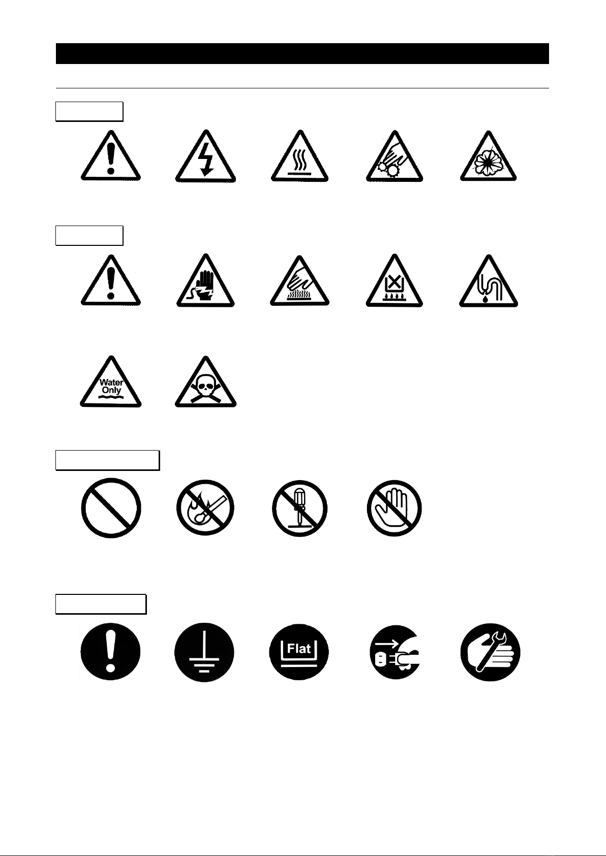
List of symbols.........................................................................2
Residual risk map ......................................................................3
Warnings・Cautions.....................................................................4
Warnings・Cautions.....................................................................5
List of residual risks ....................................................................6
2. Before operating the Equipment.................................................... 7
Precautions when installing the Equipment ................................................7
2. Before operating the Equipment.................................................... 8
Precautions when installing the Equipment ................................................8
3. Names and functions of each part ................................................. 12
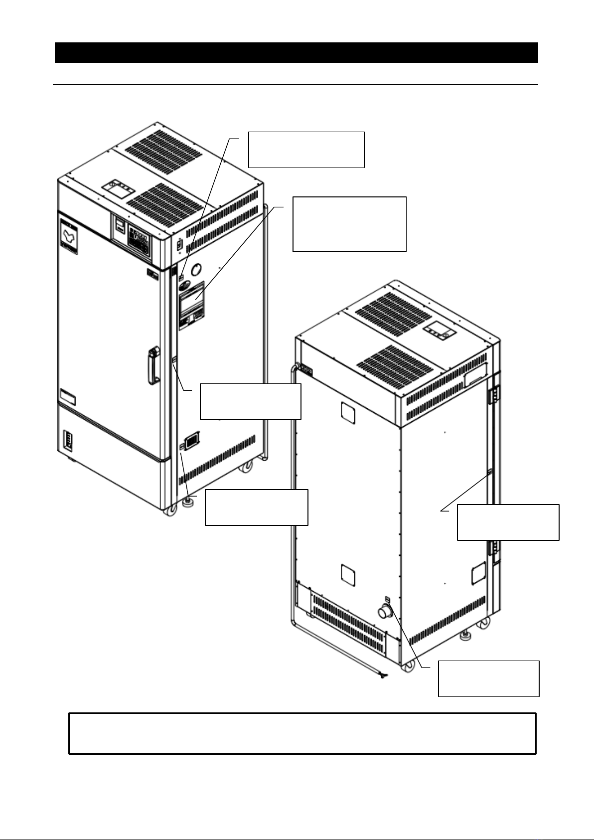
External view.........................................................................12
External view.........................................................................13
System ..............................................................................14
Structure diagram .....................................................................15
Control Panel.........................................................................16
4. Operating procedure ............................................................. 17
Prior confirmation .....................................................................17
Date & Time setting ...................................................................18
Buzzer function selection...............................................................20
Fixed temperature operation............................................................22
Auto stop operation....................................................................26
4. Operating procedure ................................................................29
Operation of the variable wind-speed function and the method of entry .......................32
Program operation ....................................................................34
Programming Method..................................................................37
How to copy or delete programs.........................................................44
About the wait function.................................................................46
Setting key lock mode .................................................................47
Calibration offset......................................................................48
Calibration offset......................................................................49
Setting the recovery mode..............................................................50
Resetting integrated CO2 volume and CO2 emission factor.................................51
Backup data saving / reading out / resetting...............................................53
Monitoring data .......................................................................54
Independent Overheat Prevention Device ................................................56
5. Handling precautions ............................................................ 57
Warnings and Cautions ................................................................57
Warnings and Cautions ................................................................58
6. Maintenance method............................................................. 63
Daily inspection/maintenance...........................................................63

7. Long storage and scrap .......................................................... 64
WhennotusingtheEquipmentforalongtime/whenscrapping...................................64
Matters to consider when scrapping the Equipment ........................................64
8. When a trouble occurs ........................................................... 65
Message error table ...................................................................65
Troubleshooting ......................................................................67
9. After sales service and warranty .................................................. 68
Request to repair parts.................................................................68
10. Specifications .................................................................. 69
Specifications ........................................................................69
11. Accessory ..................................................................... 72
List of accessories ....................................................................72
12. Wiring diagram ................................................................. 74
DNF811 Wiring diagram .............................................................74
DNF911 Wiring diagram .............................................................75
Wiring diagram part symbols............................................................76
13. List of dangerous substances.................................................... 77
14. Standard setup manual.......................................................... 78
15. Reference data ................................................................. 79
DNF811 .............................................................................79
15. Reference data ................................................................. 80
DNF911 ...............................................................................80

1. Safety Precautions
Explanation of symbols
About symbols
Various symbols are provided in this Instruction Manual and on the
product to ensure safe operation. Improper handling of this Equipment
without understanding their contents will lead to the results classified
below. Be sure to fully understand the description of symbols below
before proceeding to the text of this Manual.
Warning
Caution
Indicates a situation which may result in minor injury (Note 2)
and property damages (Note 3.)
(Note 1)Serious injury means a wound, an electrical shock, a bone fracture or
intoxication that may leave after effects or require hospitalization or
outpatient visits for a long time
(Note 2)Minor injury means a wound or an electrical shock that does not require
hospitalization or outpatient visits for a long time.
(Note 3)Property damage means damage to facilities, devices and buildings or other
properties.
Meanings of symbols
This symbol indicates a matter urging user to follow the warning
(“caution”included).
Specific description of warning is indicated near this symbol.
This symbol indicates prohibitions.
Specific prohibition is indicated near this symbol.
This symbol indicates matters that the user must perform.
Specific instruction is indicated near this symbol.
Indicates a situation which may result in death
or serious injury (Note 1.)

2
1. Safety Precautions
List of symbols
Warning
General
Warnings
Danger!: High
Voltage
Danger!: High
Temperature
Danger!: Moving
Part
Danger!:
Explosion Hazard
Caution
General Cautions
Caution:
Electrical Shock!
Caution: Burns!
Caution: Heating
Container without
water!
Caution: Water
Leak!
Caution: For
water only
Caution: Toxic
Chemicals
Prohibitions
General
Prohibited
Actions
No open flame
Do not
disassemble
Do not touch
Compulsions
General
Mandatory
Actions
Connect
grounding wire
Leveled
Installation
DisconnectPower
Regular
Inspection

3
1. Safety Precautions
Residual risk map
【DNF811】
⑲Safety indication
“BURN”
⑲Safety indication
“BURN”
⑲Safety
indication “BURN”
Caution rating sticker
③⑧⑨⑪⑬⑰⑱
⑲⑳㉑㉒㉓㉗㉘
※Contact us when the caution texts are illegible because the nameplate has peeled off or
characters are eliminated. We will send you a new name plate (for value)
⑲Safety
indication “BURN”
⑲Safety
indication “BURN”

4
1. Safety Precautions
Warnings・Cautions
【DNF911】
⑲Safety
indication “BURN”
⑲Safety indication
“BURN”
⑲Safety
indication “BURN”
Caution rating sticker
③⑧⑨⑪⑬⑰⑱
⑲⑳㉑㉒㉓㉗㉘
⑲Safety
indication “BURN”
※Contact us when the caution texts are illegible because the nameplate has peeled
off or characters are eliminated. We will send you a new name plate (for value)
⑲Safety indication
“BURN”
⑲Safety
indication “BURN”

5
1. Safety Precautions
Warnings・Cautions
List of residual risks (Instructions for avoiding risks)
This list summarizes residual risks to avoid personal injuries or damages to properties during or
related to the use of the product.
Be sure to fully understand or receive instructions on how to use, maintain and inspection of the
product before starting operation.
During or on carrying-in or installation
№
Degree of
risks
Details of risks
Protective measures to be implemented
by the machine users
Relevant
sections
①
Caution
Injury
Use cargo handling equipment for carrying and
installation. Two or more people shall be
necessary when transporting by humans.
2.3
②
Warning
Fire or
electrical shock
Carefully select an installation site and take
care for the installation environment.
2.1
③
Caution
Injury
Install on a level surface.
2.3
④
Caution
Injury
Implement safety measures for installation.
2.4
⑤
Caution
Injury
Implement appropriate safety measures after
installation.
2.5
⑥
Warning
Fire
Assure sufficient ventilation for the unit.
2.6
⑦
Warning
Fire or
electrical shock
Do not use the unit at a place that may be
subject to splashes of liquid.
2.7
⑧
Warning
Explosion or
fire
Do not use the unit in a flammable or an
explosive atmosphere.
2.8
⑨
Warning
Fire or
electrical shock
Connect the power supply to the dedicated
distribution board.
2.9
⑩
Warning
Fire or
electrical shock
Take care for handling of the power cord.
2.12
⑪
Warning
Fire or
electrical shock
Be sure to connect the ground wire.
2.10
2.11
⑫
Warning
Fire or
electrical shock
Do not disassemble nor modify the Equipment.
2.13
During operation
№
Degree of
risks
Details of risks
Protective measures to be implemented
by the machine users
Relevant
sections
⑬
Warning
Explosion and
fire
Do not use an explosive or combustible
substance.
5.1
⑭
Warning
Explosion and
fire
When using resin containers, take care not to
allow the temperature to rise beyond their
service temperature limit.
5.2
⑮
Warning
Fire or
electrical shock
Immediately turn the ELB off when an
abnormality should occur.
5.3
⑯
Warning
Fire, electrical
shock or
burning
Do not put any foreign objects in the unit.
5.4
⑰
Warning
Burning
Take extreme care for handling of specimens
after operation at a high temperature.
5.5
⑱
Warning
Burning
Take extreme care when opening the door
during operation at a high temperature.
5.6
5.26
⑲
Warning
Burning
Do not touch any hot surfaces.
5.7
⑳
Warning
Fire
Always set the sample, etc. on the dedicated
shelf plate.
2.14

6
1. Safety Precaution
List of residual risks
During operation
№
Degree of
risks
Details of risks
Protective measures to be implemented
by the machine users
Relevant
sections
㉑
Caution
Injury
Do not attempt to climb on the unit.
5.8
㉒
Caution
Injury
Do not put any objects on the unit.
5.9
㉓
Warning
Fire
Turn the ELB off when thunder is heard.
5.10
㉔
Caution
Burning and
injury
Use the unit at the appropriate temperature
(within the temperature control range).
5.13
㉕
Warning
Burning
Pay attention to the bath internal temperature at
end of operation.
5.27
㉖
Warning
Fire and
electrical shock
Take care when handling samples.
5.17
㉗
Warning
Fire
Make a temperature setting for the standalone
overheat preventive unit.
5.20
During inspection and maintenance
№
Degree of
risks
Details of risks
Protective measures to be implemented
by the machine users
Relevant
sections
㉘
Warning
Fire or
electrical shock
Inspect the ELB and the standalone overheat
preventive unit at regular intervals.
5.22
㉙
Warning
Fire or
electrical shock
Remove the power cord before inspection or
maintenance.
6
㉚
Warning
Burning
Start maintenance only after the device has
returned to the normal temperature.
6
㉛
Warning
Fire or
electrical shock
Do not attempt to disassembly the devices.
6
When you are not going to use the unit for a long time or when discarding the unit
№
Degree of
risks
Details of risks
Protective measures to be implemented
by the machine users
Relevant
sections
㉜
Warning
Fire or
electrical shock
Turn power off and remove the power cord.
7
㉝
Caution
Injury, trapping
Do not leave the unit at a place where children
may play.
7
㉞
Caution
Injury
When the equipment is to be disposed of,
remove the hinge and door lock to prevent tight
closing of the door.
7

7
2. Before operating the Equipment
Precautions when installing the Equipment
1. Choose proper place for installation
Do not install this Equipment in the place where:
・the location is rough, dirty or un-leveled.
・flammable gas, explosive gas or corrosive gas will be generated.
・ambient temperature will be more than 35℃or less than 5℃.
・ambient temperature will fluctuate. ・Liquid may splash
・there is excessive humidity and dusty. ・there is direct sunlight.
・there is constant vibration. ・outside the building.
・power supply is instable.
Install the Equipment(s) at the place with sufficient space as specified as below
An exhaust port exists in the back of main body. When the exhaust duct is not provided, install
the product while paying attention to the back space and checking for any combustibles.
【DNF811】
Min 30cm
Min 80cm
Min 30cm
Min 30cm

8
2. Before operating the Equipment
Precautions when installing the Equipment
【DNF911】
Min 30cm
Min 30cm
Min 30cm
Min 70cm

9
2. Before operating the Equipment
Precautions when installing the Equipment
2.For Ventilation
When the product is used (with the damper opened) for ventilation, take such measures as to
ensure sufficient ventilation around the installation location.When ventilation around the product
is not sufficient, hot air discharged through the exhaust port may cause increase in temperature
of the location or fume andgas generated from the sample may fill the space. Be sure to connect
the exhaust duct to the exhaust port to ensure discharge of hot air to the outside. The exhaust
duct is optionally available and should be ordered separately. See “P. 70 List of Accessories.”
3. Install the Equipment on leveled location.
Install this Equipment on leveled floor. If it is installed on rough and/or slope floor, vibration or
noise will be occurred, and unexpected trouble and malfunction may be happened.
Weight of this Equipment is as follows:
DNF811: approx. 135kg、DNF911 : approx. 210kg
Use cargo handling equipment for carrying and installation. Two or more people shall be
necessary when transporting by humans. In such an event, raise the adjuster and transport
slowly and gently.
4. Implement safety measures when installing the unit.
May be injured by moved and/or fallen this Equipment down by earthquake and/or unexpected
impact. Recommend to install this Equipment at the place away from the access door and to
take other safety steps.
5. Implement appropriate safety measures after installation.
May be injured by moved and/or fallen this
Equipment down by earthquake and/or
unexpected impact.
To ensure the safety, be sure to provide any
adequate measur to the main body and to the
installation surface to prevent overturn.
DNF811/911 provide 2 adjusters underneath
front bottom of this Equipment.
Set those adjusters by the following procedure
after this Equipment installation.
①Turn each adjuster until securely sand on the
floor.
②Check any gap between floor and 4(four)
standing points.
③Tighten each nut of its adjuster against to the
nut above to prevent loosening.
6. Ventilate sufficiently for the Equipment
Do not operate the Equipment blocked in the radiating slit holes-Louver on its side and back
panels and top panel. Refer to 3. “Name and Functions of each part” on page 11 for the location
of Louvers.
Internal temperature will rise, causing a malfunction of the controller to compromise the
performance as well as to cause a possible accident or a fire.
7. Do not operate at the location of liquid splashing.
Do not operate this Equipment at the location of liquid splashing. If Controller of this Equipment
will be wetted by splashing any kind of liquid, it may cause accident, controller malfunction,
electrical shock and/or fire.

10
2. Before operating the Equipment
Precautions when installing the Equipment
8. Never operate in an atmosphere where flammable or explosive gas is present.
Never operate this Equipment in an atmosphere where flammable or explosive gas is present.
This Equipment is not explosion-proof. Spark may be discharged by switching Earth Leakage
Breaker (ELB) “ON(|)” and “OFF(○)” and also relay during operation, and then it may cause
fire or explosion.
See Chapter 13. “List of Dangerous Substances” for flammable and explosive gases on
page .76
9. Connect Power Cord/Power Cable to receptacle or switch board of facilities.
Connect Power Cord/Power Cable to suitable receptacle/switch board of facilities according to
electrical requirements as follows.
Electrical
requirements:
DNF811 AC220Vsinglephase50/60Hz15.5Aormore(ELBcapacity;20A)
DNF911 AC220Vsinglephase50/60Hz18.5Aormore(ELBcapacity;20A)
The operational voltage range is ±10%, the voltage range where the specified performance is
guaranteed is rating±5%, the frequency is rating±1%.
※Check line voltage of its receptacle/switch board of facilities and/or whether utilize the same
line with other equipments or not, if this Equipment does not start up/operate even to turn
Earth Leakage Breaker(ELB) On(|). Take correct action for the solution, such as changing its
power source away from other equipment.
10. Must connect grounding wire properly.
・Must connect grounding wire properlyto grounding line orterminal in orderto avoid electrical
shock due to electrical leakage.
・Never connect grounding wire to gas line pipe or water line pipe due to fire or electrical
shock.
・Never connect grounding wire to telephone grounding line or to lightening conductor due to
fire or electrical shock.
・Require to ground by Electrical Equipment Technical Standards Section 19-calss
D(Grounding Resistance Max. 100Ω) in Japan, if grounding terminal is not provided. Please
contact with local dealer, local electrician, or Yamato Customer Service Center.
・Connect the terminals firmly to switch board of facilities or appropriate power plug.
・Power plug itself will not be included as an accessory of this Equipment. Connect to the
power supply facilities that meet the electric capacity.
Core color
Wiring on the
distribution board
White
Ground side
Black
Voltage side
Green
Earth
White
Black
Green

11
2. Before operating the Equipment
Precautions when installing the Equipment
11. Take care for handling of the power cord.
Never operate this Equipment at bundled Power Cord/Power Cable. May heat its Cord/Cable
and then cause fire, if operate at bundled it.
Do not modify, bend forcibly, twist or pull Power Cord/Power Cable. Otherwise, may cause fire
and/or electrical shock.
Do not damage Power Cord/Power Cable by setting under any desk and/or chairs, or by
pinching it between objects. Otherwise, may cause fire and/or electrical shock.
Do not place Power Cord/Power Cable close to kerosene heater, electric heater, or other heat-
generating devices.
Turn immediately off (○) Earth Leakage Breaker (ELB) and also disconnect Power Plug/breaker
of switch board of facilities, if it is damaged such as exposure of core wire or disconnection.
Turn immediately off (○) Earth Leakage Breaker (ELB) and also disconnect Power Plug/breaker
of switch board of facilities, if it is damaged such as exposure of core wire or disconnection.
Connect Power Cord/Power Cable to appropriate receptacle or switch board of facilities.
12. Never disassembly nor modify the Equipment.
Never disassemble nor modify this Equipment. Those actions may cause this Equipment
malfunction, fire or electric shock.
13. Installation of shelf boards and samples (Do not put samples directly on the
bottom of the chamber.)
The models DNF811 has four shelf boards and DNF911 has eight shelf boards and
One (two for DNF911) of those boards is screwed to the lowest shelf rung on the shelf pillar
inside at the time of factory shipping.
Put other shelf boards to places you want in the bath.
Placing the sample directly on the bottom of product may disturb the air circulation and make
the normal temperature control difficult, resulting in burn of the sample by abnormal
temperature and fire.Always place the sample on the shelf plate and never place it directly on
the bottom.
Do not use the shelf plates other than dedicated ones. Otherwise normal temperature
control cannot be achieved.

12
3. Names and functions of each part
External view
【DNF811】
Handle
Caution rating
nameplate
Cable port
Door
Louver
Exhaust port
Louver
Louver
独立過昇防止器
ELB
Control panel
Power cord
(with round
terminal)
Suction port
IIndependent overheat preventive device
Damper
Adjuster
Caster

13
3. Names and functions of each part
External view
【DNF911】
Caution rating
nameplate
Cable port
ELB
Control
panel
Door
Handle
Louver
Exhaust
port
Suction
port
Power cord
(with round
terminal)
Exhaust
port
Louver
Suction
port
Louver
IIndependent overheat preventive device
Damper
Caster
Adjuster

14
3. Names and functions of each part
System
The product has the variable wind-speed function. This function enables change of wind speed in 10
stages (FAN: 1 to FAN 10). Its combination with the programmed operation function enables stepwise
change of the wind speed.
Door
Inner
bath
Variable wind-speed
function
Circulation
fan
Heater
(Side view) Wind speed: 1 to 10

15
3. Names and functions of each part
Structure diagram
This product has the damper function.
The damper mechanism can change the damper opening in five stages; 0~100.With the damper opening,
the air is discharged from the inside through the exhaust port. This function is appropriate for efficient
sample drying by changing the internal air or for rapid lowering of the internal temperature. Adjust the
damper opening according to the purpose.
Shelf
plate
Shelf
support
Fan motor
Exhaus
t port
Heater
Damper
Exhaust damper filly opened
Exhaust damper fully closed
Sirocco
fan
Overheat
preventive
sensor
Temperature
control
sensor
Exhaust
port
Exhaust
port
Exhaust
port
Damper
Suction

16
3. Names and functions of each part
Control Panel
No.
Name
Description
1
Top screen
Display read temperature in Chamber and error numbers.
2
Bottom screen
Display target temperature and various information.
3
Program setting item display
Illuminate one of lamps selected from different settings.
4
Comes on during duration/time
setting and in the Monitoring
mode
Illuminate one of lamps selected from 3(three) different settings.
5
REMOTE Lamp
Illuminate during control via communication
6
FAN Llamp
lluminate this Lamp while fan motor is in operation
7
ERROR Lamp
Illuminate this Lamp at each error occurred.
8
OPERATE Lamp
lluminate this Lamp during oepration, and flash it during operation standby mode.
9
HEATER Lamp
Flashes or lights while the heater is live according to the operation amount.
10
EVENT Lamp
lluminate this Lamp at Event Output setting(option).
11
FIXED TEMP Lamp
lluminate while the fixed temperature operation mode is selected.
12
PROGRAM Lamp
lluminate in the Program operation mode.
13
AUTO START Lamp
lluminate in the Auto start mode.
14
AUTO STOP Lamp
lluminate in the Auto stop mode.
15
MODE key
Use at changing Operation Mode among No. 10 thru. No.13(⑩~⑬ on the
Panel).
16
Controller POWER key
Turn “Idle State”-(Controller is sleeping) or “Standby State”-(Controller is
awaking) of Keys(except ⑱MENU Key) by pressing and holding this key.
17
DISP key
Keep this key pressed longer to execute the Monitoring function.
This key functions as the back key for setting items while any of setting menusis
displayed.
18
START/STOP key
Use to start sellected operation or to stop working operation.
19
MENU key
Use to set target program, click on/off, output temperature range(option), and etc.
20
Esc key
Use to abort or get out of working menu without entering and/or editing set value
and items.
21
▲(Up) key
Use to change set value up.
22
▼(Down) key
Use to change set value down.
23
key
Used as the Left key for the setting digits (cursor) during setting.
24
ENTER key
Use to enter set value and items.
25
Independent overheat
preventive device
Used for setting an operating temperature of the independent overheat
preventive device.
26
Damper knob
Knob to adjust the opening of exhaust damper
▼
This manual suits for next models
1
Table of contents
Other Yamato Oven manuals

Yamato
Yamato DF Series User manual

Yamato
Yamato DVS402 User manual

Yamato
Yamato DKN302C User manual

Yamato
Yamato DKM300C User manual

Yamato
Yamato DG-450C User manual

Yamato
Yamato DE410 User manual

Yamato
Yamato DPC Series User manual

Yamato
Yamato DX302 User manual

Yamato
Yamato DNF 400 User manual

Yamato
Yamato DG400 User manual