Yamato DKM300C User manual

Forced Convection Constant
Temperature Oven
Model: DKM300C/400C/600C
DKM310C/410C/610C
Yamato Scientific America Inc.
Thank you for purchasing "Forced Convection
Constant Temperature Oven, DKMC Series" of
Yamato Scientific Co., Ltd.
To use this unit properly, read this "Instruction
Manual" thoroughly before using this unit.
Keep this instruction manual around this unit
for referring at anytime.
WARNING!:
Carefully read and thoroughly understand the
important warning items described in this
manual before using this unit.
- First Edition -

Table of Contents
1. Safety precautions........................................................................................................................................ 1
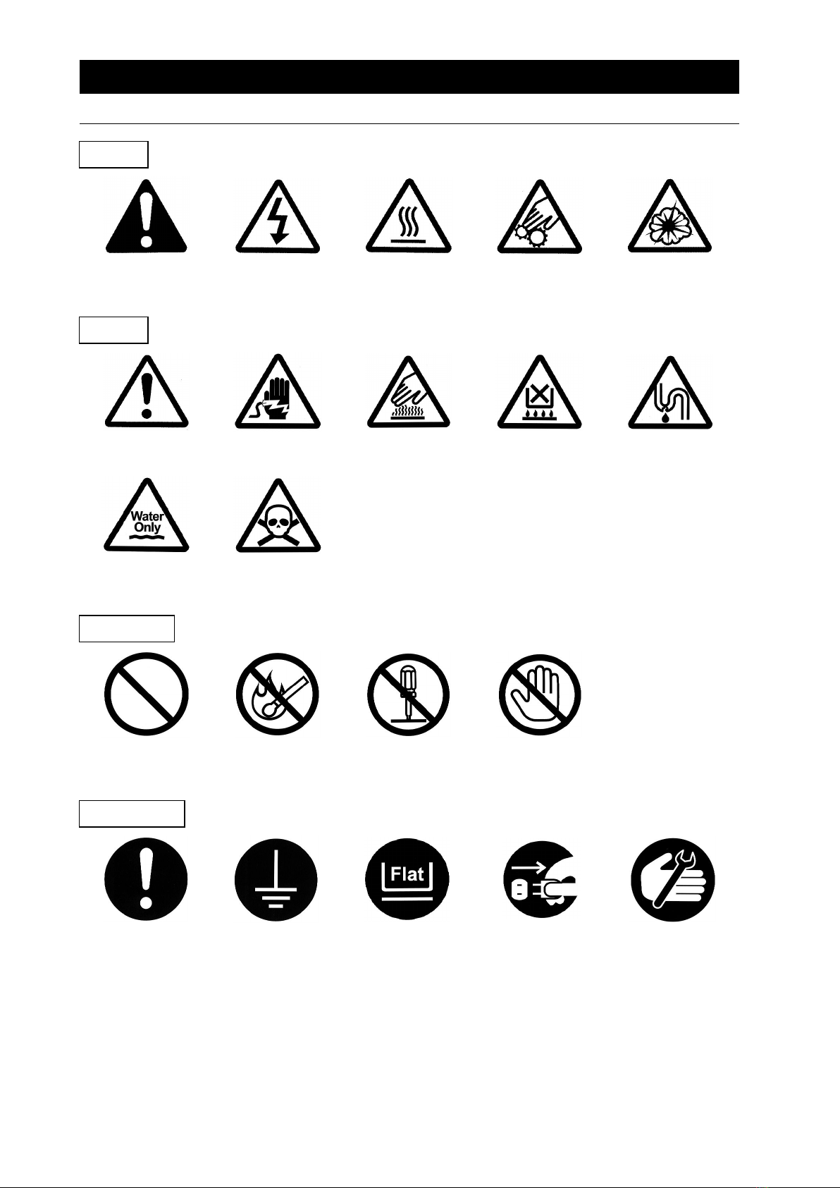
Explanation of pictograms..............................................................................................................................1
List of symbols................................................................................................................................................. 2
Warning ・Cautions....................................................................................................................................... 3
2. Before operating the unit............................................................................................................................ 4
Precautions when installing the unit.............................................................................................................4
Installation procedures ・precautions........................................................................................................ 7
3. Names and functions of parts................................................................................................................. 10
Main body....................................................................................................................................................... 10
Operation panel............................................................................................................................................. 11
Explanation of characters............................................................................................................................ 12
4. Operating procedures................................................................................................................................ 13
List of operation modes and functions.......................................................................................................13
Operation mode ・function setting keys and characters...................................................................... 15
Operating procedures (settings for overheat prevention device)..........................................................16
Operating procedures (fixed temperature operation)..............................................................................17
Operating procedures (quick auto stop operation)..................................................................................18
Operating procedures (auto stop operation)............................................................................................ 20
Operating procedures (auto start operation)............................................................................................ 22
Useful functions (calibration offset function).............................................................................................24
Useful function (setting lock function)........................................................................................................25
Useful function (power outage compensation function)......................................................................... 26
5. Cautions on handling................................................................................................................................. 27
6. Maintenance procedures...........................................................................................................................30
Daily inspection/maintenance..................................................................................................................... 30
7. When the unit is not to be used for a long time or when disposing.............................................31
When the unit is not to be used for a long time or when disposing......................................................31
Notes about disposition................................................................................................................................31
8. Troubleshooting...........................................................................................................................................32
Safety device and error codes.................................................................................................................... 32
When a malfunction is suspected...............................................................................................................33
9. After sales service and warranty............................................................................................................ 34
When requesting a repair............................................................................................................................ 34
10. Specifications.............................................................................................................................................35
11. Wiring diagram...........................................................................................................................................36
12. List of replacement parts........................................................................................................................ 36
13. List of dangerous materials................................................................................................................... 39
14. Standard installation manual.................................................................................................................40

1
1. Safety precautions
Explanation of pictograms
A variety of pictograms are indicated in this operating instruction and on products to assure
safe operation. Possible results from improper operation ignoring them are classified as
follows.
Be sure to fully understand the descriptions below before proceeding to the text.
Warning Indicates a situation which may result in death or serious injury
(Note 1)
Caution Indicates a situation which may result in minor injury (Note 2) and
property damage (Note 3).
(Note 1) Serious injury means a wound, an electrical shock, a bone fracture or intoxication
that may leave after effects or require hospitalization or outpatient visits for a long
time.
(Note 2) Minor injury means a wound or an electrical shock that does not require
hospitalization or outpatient visits for a long time.
(Note 3) Property damage means damage to facilities, devices and buildings or other
properties.
This pictogram indicates a matter that encourages the user to adhere to
warning (“caution” included).
Specific description of warning is indicated near this pictogram.
This pictogram indicates prohibitions
Specific prohibition is indicated near this pictogram.
This pictogram indicates matters that the user must perform.
Specific instruction is indicated near this pictogram.
About pictograms
Meanings of pictograms

2
1. Safety precautions
List of symbols
Warning
General warnings
Danger!:
High voltage
Danger!:
High temperature
Danger!:
Moving part
Danger!: Hazard
of explosion
Caution
General cautions Electrical shock! Burning!
Caution for no
liquid heating!
Caution for water
leak!
For water only
Poisonous
material
Prohibitions
General bans Fire ban
Do not
disassemble
Do not touch
Compulsions
General
compulsions
Connect ground
wire
Install levelly
Pull out the power
plug
Regular
inspection

3
1. Safety precautions
Warning ・Cautions
Warning
Never operate the unit in an atmosphere containing flammable or explosive gas
Never operate the unit in an atmosphere containing flammable or explosive gas.
Otherwise, an explosion or a fire may result since the unit is not explosion-proof.
See section “13. List of dangerous materials” on page 39.
Be sure to connect the ground wire.
Be sure to connect the ground wire correctly. Otherwise, electrical leak may result and cause
an electrical shock or a fire.
Ban on operation when an abnormality occurs
When a smoke or a unusual odor is seen or sensed, immediately turn the ground fault interrupter
on the main unit off and pull out the power plug. A fire or an electrical shock may result.
Never use electrical power cords bundled.
When these are used bundled, they might overheat causing a fire.
Take care not to damage electrical power cords.
Avoid tightly bend, pull with a strong force or twist to prevent electrical power cords from
damaging. A fire or an electrical shock may result.
Never use an explosive or a flammable material with this unit.
Never use an explosive material, a flammable material or a material containing them. An
explosion or an electrical shock may result.
See section “13. List of dangerous materials” on page 39.
Never try to touch a hot part.
Some parts of the unit are hot during and immediately after operation. Take special care for
possible burning.
Never try to disassemble or alter the unit.
Never try to disassemble or alter the unit. A malfunction, a fire or an electrical shock may result.
Caution
When a thunder is heard.
When a thunder is heard, turn the main power off immediately. A malfunction, fire or an
electrical shock may result.

4
2. Before operating the unit
Precautions when installing the unit
1. Carefully select an installation site.
Take special care not to install the unit at a place described below:
・Uneven surfaces or dirty surfaces
・Where flammable gas or corrosive gas exists
・Where the ambient temperature is 35℃or more
・Where temperature changes severely
・Where humidity is high
・Where subject to direct sunlight
・Where vibration is severe
Secure minimum spaces as shown below around the unit.
15 cm
or more 15 cm
or more
Front
15 cm or more
1m or more
2. Install the unit on a level surface.
Flat
Install the unit on a level surface. If the whole bottom surface of the unit does not contact
the surface evenly, vibrations or noises may result. This might cause unexpected troubles
or malfunctions.
Weight of the unit are: Model DKM300C/310C:approx 35 kg;Model DKM400C/410C:approx
50 kg;Model DKM600C/610C:approx 65 kg, When lifting the unit for transportation and
installation, carefully handle it by at least two people.
3. Installation
The unit might fall down or move by an earthquake or an impact resulting a personal injury.
We recommend to make safety measures such as to avoid installing the unit at a place other
than busy places.

5
2. Before operating the unit
Precautions when installing the unit
4. Assure sufficient ventilation for the unit.
Do not operate the unit when its vent holes on the side and rear panels covered or blocked.
Internal temperature of the unit will rise degrading the performance and an accident, a
malfunction or a fire may result.
5. Do not operate the unit at such a place that may subject to splash.
Do not operate the unit at such a place that may subject to splash. Liquid entering the
inside may cause an accident, a malfunction, an electrical shock or a fire.
6. Never operate the unit in an atmosphere containing flammable or explosive gas.
Never operate the unit in an atmosphere containing flammable or explosive gas. Since the
unit is not explosion-proof, an arc is discharged when switching the circuit breaker
interrupter “ON” and “OFF” and during operation and a fire or an explosion may result.
See the section “13. List of dangerous materials” on page 39 for flammable and explosive
gases.
Explosive gas
Combustible gas

6
2. Before operating the unit
Precautions when installing the unit
7. Be sure to connect the power plug to the dedicated power distribution panel or
a wall outlet.
Choose a correct power distribution board or receptacle that meets the unit’s rated electric
capacity.
Electrical capacity:
DKM300C AC115V 7.5A
DKM400C AC115V 11A
DKM600C AC115V 12A
DKM310C AC220V 4.5A
DKM410C AC220V 6.5A
DKM610C AC220V 7A
NOTE:
There could be the case that the unit does not run even after turning ON the power. Inspect
whether the voltage of the main power is lowered than the specified value, or whether other
device(s) uses the same power line of this unit. If the phenomena might be found, change the
power line of this unit to the other power line. Please consult your dealer or a local electrical
contractor for the connection of devices that use a single-phase 220V power source.
Do not connect the unit to any parts or lines other than a correct power supply line such as a
gas pipe, a water pipe or a telephone line.
Otherwise, an accident or a malfunction may result.
8. Handling of a power cord
Never use electrical power cords bundled. When these are used bundled, they might
overheat causing a fire.
Never alter, forcibly bend, twist or pull the power cord. Otherwise, a fire or an
electrical shock may result.
Do not put the power cord under a desk, a chair or between some objects to avoid
damaging it. Otherwise, a fire or an electrical shock may result.
Do not place the power cord close to a stove or other heat generating device.
Sheath of the cord may burn and result in a fire or an electrical shock.
If the power cord should be damaged (exposure of core wire or disconnection), immediately
turn the MCB on the main body, turn the source power off and ask your dealer to replace the
cord. Operating the unit with a damaged power cord may cause a fire or an electrical shock.
Be sure to connect the power cord to a correct wall outlet.

7
2. Before operating the unit
Installation procedures ・precautions
(1) Select an installation site.
・Make sure that all of four legs are securely on a flat surface.
(2)
Install shelf boards.
・The lowest shelf board has been secured with screws at the time of shipping from the
factory.
・Install shelf pegs at heights you want on the right and left shelf posts in the internal bath of
the main body.
・Completely push shelf boards by sliding to the end.
*Take care to put each shelf board on correct pairs of right and left shelf pegs.
・Make sure that shelf boards will not fall nor rattle.
・Withstand load of each shelf board is 15 kg in even loading. When putting samples,
arrange them as dispersed as possible.
Shelf pillar
Screw
Screw
Shelf board
Flow
adjusting
plate
Clamp
Shelf board
Sample
15 kg

8
2. Before operating the unit
Installation procedures ・precautions
・Put samples with spaces between them. Too many samples may prevent proper
temperature control. To assure proper temperature control, put samples with a space at
least 30% of the shelf board area.
Make at least 30% of space
(3)
Do not put a sample on the bottom of the internal bath.
・Operating the unit with a sample directly put on the bottom of the internal bath might
degrade its temperature characteristics. This also may cause corrosion, damage or rust
of the internal bath. Never put any sample on the bottom surface.
・When putting samples, take care not to allow them touching the wall, where sensor or other
devices are installed. Put samples on the shelf board included with the unit.
(4) Take special care for samples shown below:
(1) Samples that contain flammable or explosive components
・The unit is not explosion proof. Never attempt to dry or process materials that
contain flammable or explosive components.
(2) Corrosive samples
・Take care for handling of corrosive samples. Although SUS304 stainless steel is
used for major components, note that they might corrode with strong acid. Note that
packing may corrode with acid, alkali, oil or organic solvents.
(5)
Always operate the unit with the vent holes open.
・There are two vent holes on the top surface of the unit. In regular operation, open both of
two vent holes. Adjust their opening level according to the water amount contained in a
specific sample.
Note that high temperature steam may be blowing out of the vent
holes.
To prevent a burn, never try to look into the vent holes or touch
those parts with bare hands.
(6)
Always shut the door completely.
・Make sure that the clamp on the right side of the door is completely locked before operating
the unit.

9
2. Before operating the unit
Installation procedures ・precautions
(7)
About two-tier stacking
・Use the dedicated optional parts to stack units in two tiers. Contact you dealer or the
nearest sales office for the dedicated optional part.
(8)
Before using the unit for the first time
・When you operate the unit for the first time at a higher temperature, the unit may generate
an order. This is due to decomposed bonding material contained in heat-insulation
material and is not a malfunction of the unit. We recommend operating the unit at the
highest temperature once before starting its regular operation.

10
3. Names and functions of parts
Main body
DKM300C/400C/600C/310C/410C/610C
Front panel
Rear panel
Power switch (MCB)
Handle
Operation panel
Rating plate
Exhaust
port
Standalone overheat
protection device
(hydraulic)
Power cord
Door
Cable port

11
3. Names and functions of parts
Operation panel
M EA SURED TEM P.
℃
H EATER
R U N
SET TEM P.
R U N
STO P
TIM ER
SU B M EN U
No. Name Operation/action
①RUN/STOP key Used for starting/stopping operation.
② ▼▲ key Used for selecting settings.
③TIMER key Key for selecting timer operation settings.
Quick auto stop operation, auto stop operation or auto start
operation can be selected.
SUB MENU key
(Long press of the TIMER
key)
Key for setting calibration offset temperature, the key lock
function or the power outage compensation function.
④RUN lamp
Illuminates during fixed temperature operation and blinks
during timer operation.
⑤HEATER lamp Illuminates while heater power is on.
⑥MEASURED TEMP.
screen
Displays measured temperature in the bath/set characters/
alarm information.
⑦SET TEMP. screen Displays a set temperature, timer settings and timer remaining
time.
⑤
④
⑥
⑦
①
②
③

12
3. Names and functions of parts
Explanation of characters
Characters on the controller are explained in this section.
Characters Identifier Name Application
AStP Auto stop setting Used for setting auto stop operation
AStr Auto start setting Used for setting auto start operation
End Time up
Displayed when timer operation has
ended.
See page 18 and 20.
cAL Calibration offset setting
Used for inputting a calibration offset
temperature.
See section “Using the calibration
offset function” on page 24.
Lock Key lock of settings
Key locks settings to prevent their
alteration.
See section “Using the lock function”
on page 25.
Pon Power outage
compensation setting
Used for setting auto start operation.
See section “Using the power outage
compensation function” on page 26.
* See the section “Operation mode ・function setting keys and characters” on page 15 for characters
of operation modes and functions.

13
4. Operating procedures
List of operation modes and functions
Operation modes of the unit are as shown below:
№Name Description Page
1
Fixed temperature
operation
Turning the MCB on to enter the operation setting mode.
Proceed to temperature setting that uses ▼▲ keys.
Pressing the RUN/STOP key longer starts operation,
and pressing the RUN/STOP key longer again stops
operation.
P.17
2Quick auto
stop operation
Used when you want to “stop fixed temperature operation
being performed automatically in several hours.
Press the TIMER key during fixed temperature operation to
display “AStP.”
Set a duration before stop with the ▼▲ keys.
Pressing the RUN/STOP key starts quick auto stop operation
and activates the timer in the middle of it to automatically stop
it after the set period of time.
P.18
3 Auto stop operation
Used when you want to “set automatic stop for fixed
temperature operation when making settings for it.”
Press the TIMER key to display “AStP.”
Set a duration before stop with the ▼▲ keys.
Pressing the RUN/STOP key starts auto stop operation.
P.20
4 Auto start operation
Used when you want to “start operation automatically after
several hours” after power is turned on.
Press the TIMER key to display “AStr.”
Set a duration before stop with the ▼▲ keys.
Pressing the RUN/STOP key starts auto start operation.
P.22
* Operation mode cannot be changed while the unit is in operation. First stop operation before
changing the mode.

14
4. Operating procedures
List of operation modes and functions
Functions of the unit are as shown below:
№
Name Description Page
1Overheat prevention
function
Automatic overheat prevention function:
This function is linked to the unit set temperature and has
been set to so that it is automatically activated (returned
automatically) at a temperature 12℃higher than the set
temperature in the bath.
Standalone overheat prevention device:
When the temperature in the bath reaches the set
temperature of the overheat prevention device, its heater
circuit trips to shut off controller operation.
The temperature can be set with the manual dial on the
hydraulic overheat prevention device installed at the right
side of the unit.
P.16
2Calibration offset
function
Calibration offset function compensates any differences
between the target temperature in the bath and the control
temperature of the controller (sensor temperature.)
The function can compensate to either plus or minus side
for the whole temperature band of the unit.
This compensation can be set with the SUB MENU keys.
P.24
3 Setting lock function This function locks the set operation status.
The lock can be set or released with the SUB MENU keys. P.25
4Power outage
compensation function
This function returns the main unit operation to the resume
status after recovery from power outage, or keeps the
current stop status.
This compensation can be set with the SUB MENU keys.
P.26

15
4. Operating procedures
Operation mode ・function setting keys and characters
Key operations and characters in the diagram below are used for operation mode and function
settings.

16
4. Operating procedures
Operating procedures (settings for overheat prevention device)
As a safety measure for preventing overheat, a hydraulic overheat prevention device (manual return)
is installed.
Temperature setting range and functions
The temperature setting range for the standalone overheat prevention device is “50℃~320℃.”
When the temperature in the bath keeps rising beyond the controller set temperature and reaches the
set temperature of the overheat prevention device, the heater circuit trips and the controller operation
is shut off.
When the overheat prevention device is activated, it will not be released until the MCB is
turned on.
How to set temperature
Setting the overheat prevention temperature
・Set the temperature scale on the hydraulic overheat
prevention device installed on the right side of the unit to
the arrow in the diagram shown left.
・Turn the MCB to “OFF” and wait for a while without
opening the door.
・After a while, turn the MCB “ON.” (Turn the MCB “ON”.)
Set the temperature scale to the
arrow
Caution
①Set temperature as “set temperature +20℃” as a rough standard and add 5℃to the setting if
the device functions improperly.
②The temperature setting range for the standalone overheat prevention device is “50 ℃ ~
320℃.” Be sure to set the overheat prevention activation temperature correctly otherwise the
device may not start, the overheat prevention device is activated before temperature in the
bath increases completely, or a fire or other unexpected accidents may result.
The temperature is set at 320℃on shipping from the factory.
③If the temperature for the standalone overheat prevention device is set at around or below the
room temperature, the device may be triggered when the door is opened.
④The overheat prevention device has been designed to prevent overheating of devices not to
protect samples. The device does not prevent accidents caused from use of explosive or
flammable materials.

17
4. Operating procedures
Operating procedures (fixed temperature operation)
How to start fixed
temperature operation
1. Turn the MCB ON. (Turn the MCB to “ON.”)
When the MCB is turned ON, the initial values will be
displayed for about four seconds, then the initial screen
will appear and the current bath temperature and the
previous set temperature are displayed on each of the
indicators.
Measured temperature screen: Displays the current bath
temperature
Set temperature screen: Displays the previous set
temperature
M EA SU R ED TEM P.
℃
HEATER
R U N
SET TEM P.
STO P
RUN
M EA SU R ED TEM P.
℃
H EA TER
RUN
SE T TEM P.
TIM E R
SU B M EN U
2. Setting the temperature
Set a temperature using the ▼▲ keys.
STO P
RUN
M EA SU R ED TEM P.
℃
H EA TER
RUN
SE T TEM P.
TIM E R
SU B M EN U
3. Starting operation
Press the RUN/STOP key longer.
Fixed temperature operation will start and the RUN lamp
and the HEATER lamp come on.
4. Stopping operation
Press the RUN/STOP key longer.
Operation stops, the RUN lamp goes off and the screen
switches to the initial setting screen.
When you want to correct
setting errors or change
settings
When you want to change settings, press the ▼▲ keys on
the current screen to enter the setting mode where you can
change settings. Blink stops three seconds after three
seconds after change and setting is completed.
Caution
1When you want to lower the set temperature during fixed temperature operation,
note that it takes some time to reach the reset temperature since the unit has no
cooling capacity.
2Immediately after operation has been stopped, the temperature in the bath is
around the set temperature. Operation stop refers only to machine stop and
time needed for decreasing the temperature in the bath is not considered.

18
4. Operating procedures
Operating procedures (quick auto stop operation)
Used when you want to “stop fixed temperature operation being performed automatically in several
hours. Quick auto stop operation is a function to enable auto stop timer setting during operation.
Procedures for quick auto
stop operation
STO P
RUN
M EA SU R ED TEM P.
℃
H EA TER
RUN
SE T TEM P.
TIM E R
SU B M EN U
1. Setting time period before stop during fixed
temperature operation
①Make sure that the RUN lamp is illuminated to indicate
the unit is in operation.
Press the TIMER key.
Characters AStP are indicated on the
MEASURED TEMP. screen to indicate the auto stop
operation mode and set duration blinks on the SET
TEMP. screen.
②Set a duration you want using the ▼▲ keys.
About the timer function The maximum time that can be set for the timer is 999 hours
50 minutes.
Up to 99 hours 59 minutes, time can be set in minutes.
One hundred hours and over are set only in 10 minutes.
Keep the ▼ ▲ keys pressed to continuously change set
time and you can quickly reach the time you want. Press
the ▼▲ keys once at a time for fine adjustment.
STO P
RUN
M EA SU R ED TEM P.
℃
H EA TER
RUN
SE T TEM P.
TIM E R
SU B M EN U
2. Starting timer operation
When the time you want is set, press the RUN/STOP key
while the SET TEMP. screen is blinking.
The RUN lamp blinks and timer operation is started.
TIMER starts counting when the temperature in the bath
reaches the set temperature.
Once timer counting is started, the SET TEMP. screen
changes to the remaining time display.
STO P
RUN
M EA SU R ED TEM P.
℃
H EA TER
RUN
SE T TEM P.
TIM E R
SU B M EN U
3. Stopping and ending timer operation
Operation stops automatically when the set temperature
has elapsed.
Characters End blink on the SET TEMP. screen to
indicate operation has ended.
Press the RUN/STOP key for approx. one second to end
the timer operation mode. The screen switches to the
initial setting screen.
①
②
This manual suits for next models
5
Table of contents
Other Yamato Oven manuals

Yamato
Yamato DNF 400 User manual

Yamato
Yamato DS 400 User manual

Yamato
Yamato DG-450C User manual

Yamato
Yamato DPC Series User manual

Yamato
Yamato DKN302C User manual

Yamato
Yamato DX302 User manual

Yamato
Yamato DVS402C User manual

Yamato
Yamato DG400 User manual

Yamato
Yamato DG-440C User manual

Yamato
Yamato DF412/612 User manual