Yamato DE411 User manual

Clean Oven
DE411/611
DT411/611
Instruction Manual
First Edition
●Thank you for choosing DE411/611 and DT411/611
series Clean Ovens from Yamato Scientific Co., Ltd.
●This product is not intended for medical
applications. For laboratory drying and sterilization
use only.
●For proper equipment operation, please read this
instruction manual thoroughly before use. Always
keep equipment documentation safe and close at
hand for convenient future reference.
Warning: Read instruction manual warnings
and cautions carefully and
completely before proceeding.
Yamato Scientific America Inc.
Santa Clara,CA
.
Printed on recycled paper

Contents
1. SAFETY PRECAUTIONS...........................................................................................................1
Explanation of Symbols ...................................................................................................................... 1
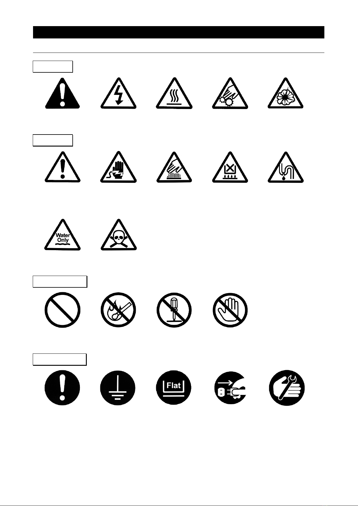
Symbol Glossary................................................................................................................................. 2
Warnings and Cautions....................................................................................................................... 3
2. PRE-OPERATION PROCEDURES ............................................................................................4
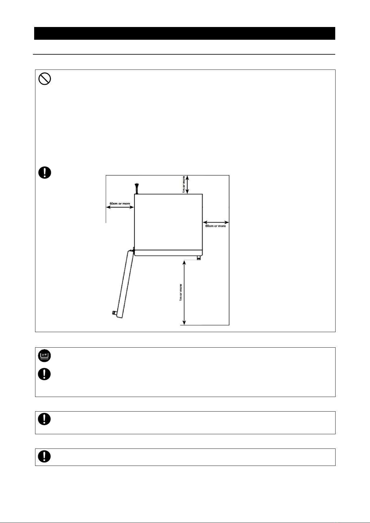
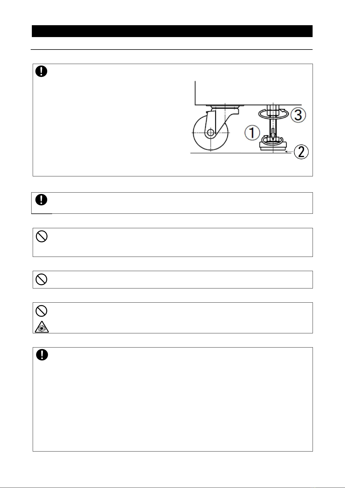
Installation Precautions & Procedures................................................................................................ 4
3. COMPONENT NAMES & FUNCTIONS......................................................................................8
Main Unit............................................................................................................................................. 8
Interior Structure................................................................................................................................. 9
Control Panel .................................................................................................................................... 10
4. OPERATION PROCEDURE.....................................................................................................11
Prior Confirmation............................................................................................................................. 11
Setting Date & Time.......................................................................................................................... 12
Buzzer function selection.................................................................................................................. 13
Constant Temperature Operation..................................................................................................... 15
Auto Stop Operation ......................................................................................................................... 19
Auto Start Operation......................................................................................................................... 22
Programmed Operation .................................................................................................................... 25
Copying & Deleting Programs .......................................................................................................... 34
Wait Function.................................................................................................................................... 36
Keypad Lock Function ...................................................................................................................... 37
Calibration Offset Function ............................................................................................................... 38
Recovery Function............................................................................................................................ 39
CO2Emissions & Power Consumption Settings............................................................................... 40
Data Backup, Data Recovery & Reset ............................................................................................. 42
Monitoring Data................................................................................................................................. 43
Independent Overheat Prevention Device........................................................................................ 45
5. HANDLING PRECAUTIONS ....................................................................................................46
Warning............................................................................................................................................. 46
Caution.............................................................................................................................................. 47
6. MAINTENANCE PROCEDURES.............................................................................................. 52
Daily Inspection & Maintenance ....................................................................................................... 52
Replacing the HEPA filter ................................................................................................................. 52
7. STORAGE AND DISPOSAL ....................................................................................................53
ExtendedStorage&UnitDisposal......................................................................................................... 53
Disposal Considerations................................................................................................................... 53
8. TROUBLESHOOTING.............................................................................................................. 54
Error Codes....................................................................................................................................... 54
Troubleshooting Guide...................................................................................................................... 56
9. SERVICE AND REPAIR...........................................................................................................57
10. SPECIFICATIONS.................................................................................................................. 58
11. ACCESSORY OPTIONS ........................................................................................................60
Accessory Item List........................................................................................................................... 60
12. WIRING DIAGRAM................................................................................................................. 62
DE411/611 DT411/611................................................................................................................... 62

Wiring Diagram Glossary.................................................................................................................. 63
13. HAZARDOUS SUBSTANCES LIST....................................................................................... 64
14. SETUP CHECKLIST...............................................................................................................65
APPENDIX 1 ................................................................................................................................ 66
Program Planning Worksheet........................................................................................................... 66

1
1. SAFETY PRECAUTIONS
Explanation of Symbols
A Word Regarding Symbols
Various symbols are provided throughout this text and on equipment to ensure
safe operation. Failure to comprehend the operational hazards and risks
associated with these symbols may lead to adverse results as explained
below. Become thoroughly familiar with all symbols and their meanings by
carefully reading the following text regarding symbols before proceeding
Warning
Caution
Signifies a situation which may result in minor injury (Note 2)
and/or property damage (Note 3.)
(Note 1) Serious injury is defined as bodily wounds, electrocution, bone
breaks/fractures or poisoning, which may cause debilitation requiring
extended hospitalization and/or outpatient treatment.
(Note 2) Minor injury is defined as bodily wounds or electrocution, which will not
require extended hospitalization or outpatient treatment.
(Note 3) Property damage is defined as damage to facilities, equipment, buildings or
other property.
Symbol Meanings
Signifies warning or caution.
Specific explanation will follow symbol.
Signifiies restriction.
Specific restrictions will follow symbol.
Signifies an action or actions which operator must undertake.
Specific instructions will follow symbol.
Signifies a situation which may result in serious
injury or death (Note 1.)

2
1. SAFETY PRECAUTIONS
Symbol Glossary
Warning
General Warning
Danger!: High
Voltage
Danger!:
Extremely Hot
Danger!: Moving
Parts
Danger!:
Blast Hazard
Caution
General Caution
Caution:
Shock Hazard!
Caution:
Burn Hazard!
Caution: Do Not
Heat Without
Water!
Caution: May
Leak Water!
Caution:
Water Only
Caution: Toxic
Chemicals
Restriction
General
Restriction
No Open Flame
Do Not
Disassemble
Do Not Touch
Action
General Action
Required
Connect Ground
Wire
Level Installation
Required
DisconnectPower
Inspect
Regularly

3
1. SAFETY PRECAUTIONS
Warnings and Cautions
Warning
NEVER operate equipment near combustible gases/fumes.
Do not install or operate DE/DT series unit near flammable or explosive gases/fumes. Unit
is NOT fire or blast resistant. Negligent use could cause a fire/explosion.
See “List of Hazardous Substances” (P.64).
ALWAYS ground equipment.
Always ground equipment properly to avoid electric shock.
DO NOT operate equipment when abnormalities are detected.
If smoke or unusual odors begin emitting from unit, or if any other abnormalities are
detected, terminate operation immediately, turn off main power switch (Earth Leakage
Breaker - “ELB”) and disconnect power cable. Continued operation under such conditions
may result in fire or electric shock.
DO NOT operate equipment with bundled or tangled power cable.
Operating unit with the power cable bundled or otherwise tangled may cause power cable to
overheat and/or catch fire.
DO NOT damage power cable.
Damaging the power cable by forcibly bending, pulling or twisting may cause fire or electric
shock to the operator.
NEVER process explosive or combustible substances.
Attempting to process/use explosive or combustible substances in/near unit may cause
explosion or fire. See “List of Hazardous Substances” (P.64).
NEVER disassemble or modify equipment.
Attempting to dismantle or modify unit in any way, may cause malfunction, fire or electric
shock.
DO NOT touch hot surfaces.
Some surfaces on this unit become extremely hot during operation. Exercise vigilance in
order to avoid getting burned.
Caution
DO NOT operate equipment during thunderstorms.
In the event of a thunderstorm, terminate operation and turn off main power switch (ELB)
immediately. A direct lightning strike may cause damage to equipment, or result in fire or
electric shock.

4
2. PRE-OPERATION PROCEDURES
Installation Precautions & Procedures
1. Choose an appropriate installation site.
DO NOT install unit:
・where flammable or corrosive gases/fumes will be generated.
・where ambient temperature will exceed 35ºC, will fall below 5ºC or will fluctuate.
・in excessively humid or dusty locations.
・where there is constant vibration.
・where power supply is erratic.
・in direct sunlight or outdoors.
Install DE/DT series unit in a location with sufficient space, as specified as below.
2. Install on a level surface.
Install unit on level and even surface. Failure to do so may cause abnormal vibrations or noise,
resulting in possible complications and/or malfunction.
Approximate weights:
DE/DT411: approx. 200kg DE/DT611: approx. 270kg
Handle unit with care. Transportation and installation should always be done by two or more
people.
3. Install in a safe location.
In the event of an earthquake or other unforeseen incident, equipment may unexpectedly shift or
fall, causing injury. Taking preventative steps to install unit in a safe location, away from room
access doors and out of harm’s way, is strongly recommended.
4. Remove protective caster covers with care.
Units are delivered with protective coverings (gray cover tubes) on casters. Gently remove them
using a utility knife, exercising care not to damage the casters or inflict personal injury.

5
2. PRE-OPERATION PROCEDURES
Installation Precautions & Procedures
5. Position adjustable leveling feet.
Position the 2 (two) adjustable leveling feet,
located on the undercarriage of DE/DT units.
After unit installation is complete, position the
adjustable leveling feet using the following
procedure:
1) Rotate leveling feet down until unit stands
securely on the floor.
2) Check for gaps between floor and 4
(four) contact points (e.g. the 2 ‘two’ front
leveling feet and the 2 ‘two’ rear casters).
3) Once unit is secure, tighten both leveling feet
stop nuts firmly against the topmost nut to
prevent leveling feet from turning under
vibration.
6. Check stability.
Unit may tip over or fall, causing injury or death during an earthquake or other unforseen
incident. Be sure to stabilize unit properly (adjustable leveling feet securely positioned, etc.) to
assure safe operation and a safe work area.
7. Install in a well-ventilated area.
Install unit so that side panel heat vents (see P.8 for location) are unobstructed and allowed to
sufficiently diffuse heat. Failure to do so may result in excessive temperatures inside the unit
control panel, causing possible degraded CPU board performance, malfunction or fire. See
installation specifications above.
8. Install in a dry location.
Install unit where it will be free from liquid spray and other moisture. Failure to do so may result
in control mechanisms becoming wet, causing malfunction, electrical shock and/or fire.
9. Install in a location free of flammables and explosives.
Never install near flammables or explosives. Unit is NOT fire or blast resistant. Simply switching
the main power switch (ELB) “ON” or “OFF” can produce a spark, which could relay during
operation, causing a fire or explosion when near flammable or explosive fluids, chemicals or
gases/fumes. See “List of Hazardous Substances” (P.64).
10. Connect to a proper power supply terminal.
Connect power cable to a suitable facility outlet or terminal, according to the following electrical
requirements.
Power
requirements:
DE411 AC220V 3 phase 50/60Hz 7.0 A
DE611 AC220V 3 phase 50/60Hz 10.0A
DT411 AC220V 3 phase 50/60Hz 10.0A
DT611 AC220V 3 phase 50/60Hz 14.0A
Standard test conditions with no load should be as follows. Operational voltage range: ±10%,
Voltage range at which specified performance is guaranteed: ±5%, Frequency rating: ±1%,
Atmospheric pressure range: 86kPa ~ 06kPa, Ambient temperature: 23±5: Humidity: 65±5%.
Check the line voltage on outlet or terminal to be used and properly evaluate whether to utilize
a line being shared by other equipment. If the unit is not activated by turning on the main power
switch (ELB), take an appropriate course of action, such as connecting the unit to a dedicated
power source.
Multiple power cables connected to a single outlet may cause unit input voltage to drop,
resulting in degraded heating and temperature control performance.

6
2. PRE-OPERATION PROCEDURES
Installation Precautions & Procedures
11. Triple phase power cable MUST be connected properly.
DE/DT models are designed to operate in triple phase at 220V AC. Determine phasing capability
of facility power supply (single phase vs. triple phase) before attempting to connect power cable.
Power connections for these units require specialized knowledge and skill. Contact Yamato
dealer or a certified electrician about performing necessary electrical work and power cable
connections. Electrical work and connections performed by anyone other than a qualified
technician may result in malfunction, fire or electric shock.
Core color
Wiring on the
distribution board
Red
Phase R
White
Phase S
Black
Phase T
Green
Earth
If three-phase (R, S, T) connection is configured incorrectly, “fan error” will be displayed when
unit is powered on and fan motor will not rotate. In this event, change any two of the three wires.
Error will clear and fan motor will operate normally.
Confirm that differential pressure gauge indicator is beyond the halfway point and in the green
zone.
12. Handle power cable with care.
Never operate unit with power cable bundled or tangled; and do not modifiy, bend, forcibly twist
or pull on power cable. Doing so may cause fire and/or electrical shock.
Do not risk damage to power cable by positioning it under desks or chairs, or by allowing it to be
pinched in between objects. Doing so may cause fire and/or electrical shock.
Do not place power cable near kerosene/electric heaters or other heat-generating devices.
Doing so may cause power cable insulation to overheat, be damaged and/or catch fire, which
may result in electric shock.
Turn off main power switch (ELB) immediately and disconnect from facility terminal or outlet, if
power cable becomes partially severed or damaged in any way. Failure to do so may result in
fire or electric shock. Contact a local dealer or Yamato sales office for assistance in replacing
power cable if it is damaged.
Always connect power cable to appropriate facility outlet or terminal.
13. Ground wire MUST be connected.
・Grounding to Electrical Equipment Technical Standards, Section 19, class D (Grounding
Resistance Max. 100Ω) is required in Japan when no grounding terminal is provided.
Contact a local dealer, electrician, or Yamato Sales office for location-specific electrical
requirements.
・Connect terminals securely to facility terminal or to an appropriate connector.
・Plugs and connectors are not included with this unit. Ground unit properly to facility outlet or
terminal as required.
Core color
Facility
Red
Phase R
White
Phase S
Black
Phase T
Green
Earth
Never connect ground wire to gas lines, water pipes, telephone grounding lines or lightning
rods. Doing so may result in fire or electrical shock.
Earth
Ground

7
2. PRE-OPERATION PROCEDURES
Installation Precautions & Procedures
14. DO NOT disassemble or modify.
Attempting to disassemble or modifiy this unit in any way may result in malfunction, fire or
electric shock.
15. Chamber rack installation and sample placement.
Install rack guides in desired position inside chamber before initial use.
Placing samples directly on bottom chamber surface may overheat samples, cause spills or
lead to other mishaps. Temperature control may likewise become inaccurate, causing
malfunction, fire or other equipment damage.
Always place samples on supplied chamber racks only; never on bottom chamber surface.
Use optional basket-type racks for processing smaller items (See P.60).
16. Exhaust precautions.
When leaving exhaust damper open for ventilation during operation, removing cover from the
intake port is recommended
Remove the three screws from port cover at the right side of unit and remove.
Store the screws and intake port for safekeeping and later use.
Before using exhaust damper for ventilated operation, take proper measures to assure
adequate work area ventilation. Failure to do so may cause excessive work area temperatures
due to heat from exhaust. Likewise, smoke and other harmful fumes may be emitted into work
area from samples in process. Implement proper ventilation measures, such as by installing an
exhaust hood or by running a proper duct from the exhaust port.
Exhaust port diameter is 61mm.

8
3. COMPONENT NAMES & FUNCTIONS
Main Unit
Exterior view
Louver
Exhaust Port
Heat Vent
Rating &
Production
Label
Cable Port
Intake Port
Heat Vent
Leveling Foot
Flow Meter Blank
for N2Gas Option
Door
Door Handle
Control Panel
Main Power Switch (ELB)
Terminal Block Blank for
Optional Outputs
HEPA Filter
Access Panel
Heat Vent
Power Cable
Heat Vent

9
3. COMPONENT NAMES & FUNCTIONS
Interior Structure
Exhaust Port
Temp Control Sensor
HEPA Filter
Sirocco Fan
Fan Motor
Caster
Leveling Foot
Heater
Support Post
Chamber Rack
Rack Support

10
3. COMPONENT NAMES & FUNCTIONS
Control Panel
No
Name
Description
1
Upper Display
Readout for chamber temperature, error code, etc.
2
Lower Display
Readout for temperature setting, clock, timer, etc
3
Function Indicator Lamps
Illuminates (one or more) to show which function is currently running or active
4
Mode Indicator Lamps
Illuminates (one at a time) to show which mode is currently running.
5
REMOTE Indicator Lamp
Illuminates while remote comm (optional item) transmission is in progress.
6
ERROR Indicator Lamp
Illuminates when an error has occured.
7
OPERATE Indicator Lamp
Illuminates while in operation. Flashes in operation standby mode.
8
HEATER Indicator Lamp
Illuminates when heaters are on and drawing power.
9
EVENT Indicator Lamp
Illuminates when event output (optional item) is transmitted.
10
FIXED TEMP Indicator Lamp
Illuminates while constant temperature operation is in progress.
11
PROGRAM Indicator Lamp
Illuminates while programmed operation is in progress. Flashes while entering
program settings.
12
AUTO START Indicator Lamp
Illuminates while auto start operation is in progress.
13
AUTO START Indicator Lamp
Illuminates while auto stop operation is in progress.
14
MODE key
Press to switch between operation modes, ⑩~⑬on control panel.
15
POWER key
Press and hold to switch between unit idle and unit standby.
16
DISPLAY key
Press to switch between monitoring options in lower display.
17
START/STOP key
Press to start or stop an operation.
18
MENU key
Press to switch between setting options.
19
ESCAPE key
Press to return to previous menu without finalizing settings
20
▲(Up) key
Press to increase setting value incrementally. Press and hold to increase
perpetually.
21
▼(Down) key
Press to decrease setting value incrementally. Press and hold to decrease
perpetually
22
key
Press to move cursor left.
23
ENTER key
Press to finalize setting items
24
Independent Overheat
Prevention Device
Set device to keep unit from exceeding a predetermined temperature.
25
Filter Gauge
HEPA filter monitoring gauge
26
Damper Lever
Damper aperture adjustment mechanism
▼

11
4. OPERATION PROCEDURE
Prior Confirmation
1. Check power supply and ground wire.
Confirm unit power cable is connected to a proper power source and grounded.
2. Check main power switch (ELB).
Confirm that ELB functions properly.
See “Maintenance Procedures”(P.52).
Check ELB performance once a month or before extended perpetual operation.
Current time shows in control panel lower display when ELB is ON (|).
3. Check Independent Overheat Prevention Device.
Confirm that IOPD temperature is set 20ºC above unit temperature setting.
Check IOPD performance before extended operations. See “Independent Overheat Prevention
Device” (P.45).
4. Check exhaust damper aperture.
Confirm that damper aperture is set properly. Close exhaust damper completely if ventilation is
not required.

12
4. OPERATION PROCEDURE
Setting Date & Time
The backup battery installed in DE/DT series units, is a wear item and has an estimated life of
approximately 5 years. Replacing battery within the 5-year lifespan is recommended.
Contact a local dealer or Yamato sales office to request a replacement battery. If unit has
program data in memory, backup these settings before replacing backup battery. See P.42 of this
manual for details.
To set the current date & time subsequent to backup battery replacement, follow the steps below.
1
Turn on power.
Turn ON the main power switch (ELB), located on the right
panel of the DE/DT series units.
Lower display on the control panel will show the time.
This indicates that the machine is in “idle”.
Press and hold to display the standby screen.
Upper display shows current temperature in the chamber,
while lower display shows current temperature setting.
This indicates that machine is in “standby”.
Fan begins running (runs when door is closed and stops
whenever door is opened).
2
Go to date/time setting menu.
1) Press repeatedly until is shown
in lower display. Press .
2) Press to bring up year in upper display
and month/day/time in lower display. Clock
indicator lamp flashes.

13
4. OPERATION PROCEDURE
Setting Date & Time
3
Set the date.
1) Press .
2) Set the current year using and press
.
3) Set month/date using and press
.
Press to move cursor position.
4
Set clock.
1) Press .
2) Press and set clock using .
Press .
Enter time using 24-hour (military time) system.
Press to move cursor position.
3) Press twice to restore initial screen once
setting is completed.
Buzzer function selection
3
Set the date.
4) Press .
5) Set the current year using and press
.
6) Set month/date using and press
.
Press to move cursor position.
4
Set clock.
4) Press .
5) Press and set clock using .
Press .
Enter time using 24-hour (military time) system.
Press to move cursor position.
6) Press twice to restore initial screen once
setting is completed.

14
4. OPERATION PROCEDURE
Mode & Function Flow

15
4. OPERATION PROCEDURE
Constant Temperature Operation
FIXED TEMP (constant temperature) mode runs DE/DT unit at a constant selected temperature
until START/STOP key is pressed, manually terminating operation.
SV: Set Value (temperature setting), t:Time
Setting constant temperature mode.
1
Turn on power
Turn ON (|) main power switch (ELB) (idle).
Press and hold to turn on control panel power.
(Standby)
Current temperature reading is shown in upper display,
Temperature setting is shown in lower display.
Fan begins running (runs when door is closed and
stops whenever door is opened).
2
Select constant temperature mode.
Press (repeatedly if needed) until FIXED TEMP
lamp lights.
Fixed Temperature mode is factory default.
Once mode has been changed, the last mode
run will be selected on subsequent startups.
3
Set temperature.
1) Press . Changeable digits flash in lower
display.
2) Change digit positions using and
increase or decrease value using .
Operating temperature ranges:
DE411/611: 0~260ºC
DT411/611: 0~360ºC
3) Press when temperature setting has
been entered.
▲
Operation start (manual)
SV
t
▲
Operation stop (manual)

16
4. OPERATION PROCEDURE
Constant Temperature Operation
4
Start operation.
Press to start operation.
OPERATE and HEATER lamps light and temperature
begins building.
Lower display in heat build phase:
Lower display in temperature stabilization:
Lower display in cooling phase:
5
Pause/stop operation
Press to manually terminate operation.
Start screen will be restored. Press to begin
operation once again, if desired.
Fan motor continues running regardless of wheter
operation is stopped. Press and hold to turn
off control panel and stop fan.

17
4. OPERATION PROCEDURE
Constant Temperature + Quick Auto Stop Operation
6
Set timer
The quick auto stop function is used to automatically stop
constant temperature operation at a certain time (by clock)
or after a desired duration (by timer). (decided during
operation).
1) Press with constant temperature operation in
progress.
2) is shown in lower display. “TIME” lamp
(top-left in lower display) flashes.
3) Select TIME (timer) or CLOCK using and
press .
4) Set TIME (setting range: 0~99hr:59min) or
CLOCK (24-hour time system) in upper display and
press .
Example 1. Quick Auto Stop function set to timer:
Operation stops automatically 35 hours and 30 minutes
after temperature setting is reached.
Example 2. Quick Auto Stop function set to clock:
Operation stops automatically at 15:00 (3:00PM).
5) AUTO STOP lamp lights and Auto Stop function
begins.
Press at any time during operation to monitor
remaining time in the lower display.
Remaining time display (timer):
Stop time display (clock):
Press again or wait about 10 seconds for
screen to return to initial screen.
This manual suits for next models
3
Table of contents
Other Yamato Oven manuals

Yamato
Yamato DX302C User manual

Yamato
Yamato DR 200 User manual

Yamato
Yamato DVS402C User manual

Yamato
Yamato DX302 User manual

Yamato
Yamato DF Series User manual

Yamato
Yamato DE410 User manual

Yamato
Yamato DG400 User manual

Yamato
Yamato DKN302C User manual

Yamato
Yamato DS 400 User manual

Yamato
Yamato DF412/612 User manual