Yamato DPC Series User manual

Vacuum Drying Oven
Model DP83C/104C
Third Edition
● Thank you for purchasing "DPC Series Vacuum Drying
Oven" of Yamato Scientific America Co., Ltd.
● To use this unit properly, read this "Instruction Manual"
thoroughly before using this unit. Keep this instruction
manual around this unit for referring at any time.
WARNING: Carefully read and thoroughly understand
the important warning items described in this manual
before using this unit.
Yamato Scientific America Inc.

Contents
1. Cautions in using with safety ........................................................................................................ 1
Explanation .......................................................................... 1
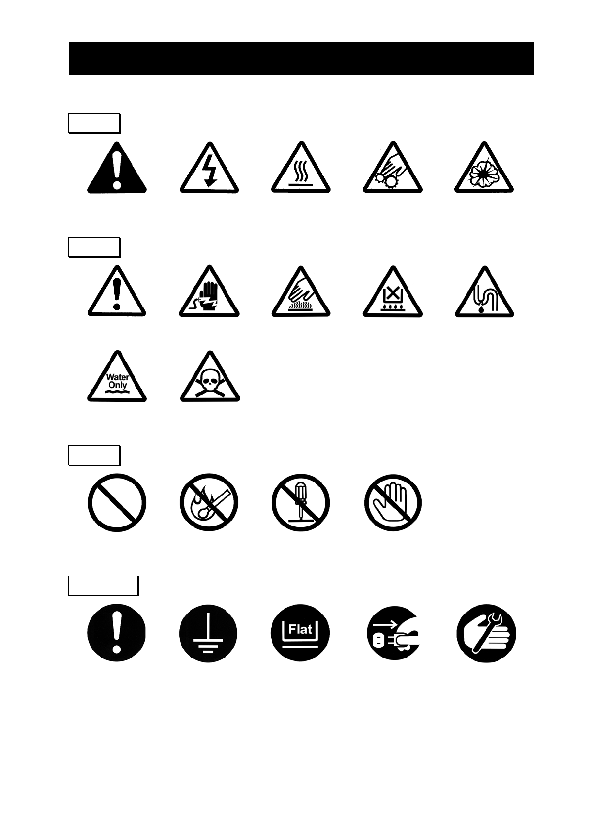
Table of Illustrated Symbols ............................................................ 2
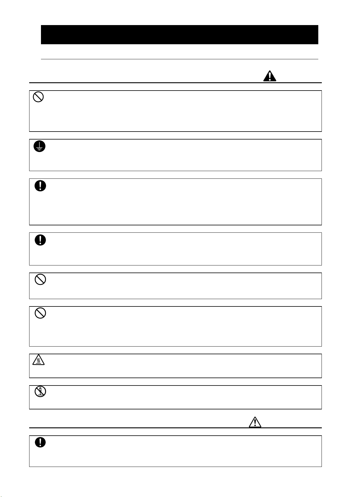
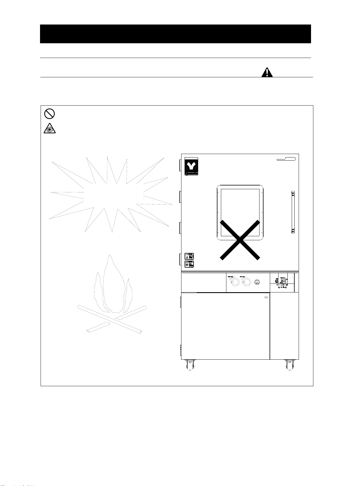
Fundamental Matters of "WARNING!" and "CAUTION!" .................................... 3
2. Before using this unit .................................................................................................................... 4
Requirements for Installation ........................................................... 4
3. Description and Function of Each Part ........................................................................................ 9
Main Unit ............................................................................ 9
Operation Panel ..................................................................... 11
Characters of the Controller ........................................................... 12
4. Operation Method ........................................................................................................................ 14
Operation Mode and Function List ..................................................... 14
Operation Mode, Function Setting Key, and Characters ................................... 16
Setting of Overheating Prevention Device ............................................... 17
Fixed Temperature Operation .......................................................... 18
Quick Auto Stop Operation ............................................................ 19
Auto Stop Operation ................................................................. 21
Auto Start Operation ................................................................. 23
Program Operation .................................................................. 25
Program Repeat Function ............................................................. 30
Programming Preparation Form ....................................................... 31
Other Functions (Calibration) .......................................................... 33
Other Functions (Lock) ............................................................... 34
Vacuumizing and air inflow ............................................................ 35
5. Handling Precautions .................................................................................................................. 36
6. Maintenance Method ................................................................................................................... 38
Daily Inspection and Maintenance ...................................................... 38
7. Long storage and disposal ......................................................................................................... 39
When not using this unit for long term / When disposing ................................... 39
Disposal Notice ..................................................................... 39
8. In the Event of Failure .................................................................................................................. 40
Safety Device and Error Code ......................................................... 40
Trouble Shooting .................................................................... 41
9. After Service and Warranty ......................................................................................................... 42
When requesting a repair ............................................................. 42
10. Specification ............................................................................................................................... 43
11. Wiring Diagram ........................................................................................................................... 45
12. Replacement Parts Table ........................................................................................................... 47
13. List of Dangerous Substances .................................................................................................. 48
14. Installation Manual ..................................................................................................................... 49

1
1. Cautions in using with safety
Explanation
MEANING OF ILLUSTRATED SYMBOLS
Various symbols are used in this safety manual in order to use the unit without
danger of injury and damage of the unit. A list of problems caused by ignoring
the warnings and improper handling is divided as shown below.Be sure that you
understand the warnings and cautions in this manual before operating the unit.
WARNING! If the warning is ignored, there is the danger of a problem that
may cause a serious accident or even fatality.
CAUTION! If the caution is ignored, there is the danger of a problem that may
cause injury/damage to property or the unit itself.
Meaning of Symbols
This symbol indicates items that urge the warning (including the caution).
A detailed warning message is shown adjacent to the symbol.
This symbol indicates items that are strictly prohibited.
A detailed message is shown adjacent to the symbol with specific actions not to
perform.
This symbol indicates items that should be always performed.
A detailed message with instructions is shown adjacent to the symbol.
Illustrated Symbols

2
1. Cautions in using with safety
Table of Illustrated Symbols
Warning
Warning,
generally
Warning,
high voltage
Warning,
high temperature
Warning,
drive train
Warning,
explosive
Caution
Caution,
generally
Caution,
electrical shock
Caution,
scald
Caution,
no load heating
Caution,
not to leak
Caution,
water only
Caution,
deadly poison
Prohibit
Prohibit,
generally
Prohibit,
inflammable
Prohibit,
to disassemble
Prohibit,
to touch
Compulsion
Compulsion,
generally
Compulsion,
connect to the
grounding
terminal
Compulsion,
install on a flat
surface
Compulsion,
disconnect the power
plug
Compulsion,
periodical
inspection

3
1. Cautions in using with safety
Fundamental Matters of "WARNING!" and "CAUTION!"
Warning
Do not use this unit in an area where there is flammable or explosive gas
Never use this unit in an area where there is flammable or explosive gas. This unit is not explosion-proof.
An arc may be generated when the power switch is turned on or off, and fire/explosion may result. (Refer
to page 48 "13. List of Dangerous Substances ".)
Always ground this unit
Always ground this unit on the power equipment side in order to avoid electrical shock due to a power
surge.
If a problem occurs
If smoke or strange odor should come out of this unit for some reason, turn off the power key right away,
and then turn off the circuit breaker and the main power. Immediately contact a service technician for
inspection. If this procedure is not followed, fire or electrical shock may result. Never perform repair work
yourself, since it is dangerous and not recommended.
Do not use the power cord if it is bundled or tangled
Do not use the power cord if it is bundled or tangled. If it is used in this manner, it can overheat and fire
may be caused.
Do not process, bend, wring, or stretch the power cord forcibly
Do not process, bend, wring, or stretch the power cord forcibly. Fire or electrical shock may result.
Substances that cannot be used
Never use explosive substances, flammable substances and substances that include explosive or
flammable ingredients in this unit. Explosion or fire may occur. (Refer to page 48 "13. List of Dangerous
Substances ".)
Do not touch high-temperature parts
The inside of the body or the door may become hot during and just after operation. It may cause burns.
Do not disassemble or modify this unit
Do not disassemble or modify this unit. Fire or electrical shock or failure may be caused.
Caution
During a thunder storm
During a thunderstorm, turn off the power key immediately, then turn off the circuit breaker and the main
power. If this procedure is not followed, fire or electrical shock may be caused.

4
2. Before using this unit
Requirements for Installation
Warning
1. Always ground this unit
・ In order to avoid electric shock caused by electric leakage, be sure to connect the earth
wire (the green cable of power cord) to the grounding wire or ground terminal.
・ This unit uses single-phase 220V power source. Please entrust your local electrical
contractor for power connecting work, grounding as per electrical device technical
benchmark.
・ Do not connect the earth wire to gas or water pipes. If not, fire disaster may be caused.
・ Do not connect the earth wire to the ground wire of telephone or lightning conductor. If
not, fire disaster or electric shock may be caused.
・
緑
M5用丸端子
黒
白
・ The power plug is not accessory.
Please correctly connect the
ground wire as per the power
source device.
2. Choose a proper place for installation
Do not install this unit at a place where:
Rough or dirty surface.
Flammable gas or corrosive gas is generated.
Ambient temperature exceeds 35C.
Ambient temperature fluctuates violently.
There is direct sunlight.
There is excessive humidity and dust.
There is a constant vibration.
Install this unit on a stable place with the space as shown below.
15cm
以上
15cm
以上
手前側
15cm 以上
1m以上
M6 type O-terminal
1.5M
Yellow green
White
Black
DP103C specification is 3-phase 480V, please connect with matched distributor
Over 15cm
Over 15cm Over 15cm
Over 1.5m
Front side

5
2. Before using this unit
Requirements for Installation
Warning
3. Do not use this unit in an area where there is flammable or explosive gas
(Refer to page 48 "13. List of Dangerous Substances ".)
Never use this unit in an area where there is flammable or explosive gas. This unit is not
explosion-proof. An arc may be generated when the power switch is turned ON or OFF, and
fire/explosion may result.
SINCE 1889
可燃性气体
爆炸性气体
Vacuum Drying Oven DP83C
Explosive gas
Flammable gas

6
2. Before using this unit
Requirements for Installation
Warning
4. Do not modify 5. Installation on horizontal surface
Modification of this unit is strictly
prohibited. It may cause a failure.
Set this unit to the flattest place. Setting this
unit on rough or slope place could cause the
vibration or noise, or cause the
unpredictable trouble or malfunction.
SINCE 1889 DP83C
Vacuum Drying Oven
改造
SINCE 1889DP83C
Vacuum Drying Oven
6. Do not make an overload
7. Do not set samples in close formation
The withstand load of shelf is 15kg
(uniform load). Set the samples apart each
other.
The temperature in furnace cannot be
controlled if too much samples are set there.
Make sure to use the shelf and set samples
apart each other so as to make the free
space of 30% or more to the furnace to
acquire accuracy of temperature.
Make the free space of 30% or more
Samples
15kg
Shel
f
Do not modify

7
2. Before using this unit
Requirements for Installation
Caution
8. Choose a correct socket
Choose a correct power socket that meets the unit’s rated electric capacity.
Electric capacity DP83C AC220V 18.5A (not contain vacuum pump current)
DP104C 3-phase 480V 17.5A (not contain vacuum pump current)
There could be the case that the unit does not run even after turning ON the power. Inspect
whether the voltage of the main power is lowered than the specified value, or whether other
device(s) uses the same power line of this unit. If the phenomena might be found, change the
power line of this unit to the other power line. This unit does not have plug, please consult
your dealer or a local electrical contractor for power connection.
9. Installation and layout
It may cause injure to a person if this unit falls down or moves due to earthquake or impact.
To prevent, take measures that the unit cannot fall down, and not install at a busy place.
The unit is equipped with casters, check if the casters are locked.
Hang the caster handle, in front of the caster, over its tyre from side.
10. First use
When first using the unit, it may stink once there is high temperature. The odor is generated
from insulation materials decomposing. It is not machine failure. It’s better to have a
high-temperature operation before using.
11. Handling of power cord
Do not entangle the power cord. This will cause overheating and possibly a fire.
Do not bend or twist the power cord, or apply excessive tension to it. This may cause a fire
and electrical shock.
Do not lay the power cord under a desk or chair, and do not allow it to be pinched in order
to prevent it from being damaged and to avoid a fire or electrical shock.
Keep the power cord away from any heating equipment such as a room heater. The cord's
insulation may melt and cause a fire or electrical shock.
If the power cord becomes damaged (wiring exposed, breakage, etc.), immediately turn off
the power at the rear of this unit and shut off the main supply power. Then contact your
nearest dealer for replacement of the power cord. Leaving it may cause a fire or
electrical shock.
Connect the power plug to the receptacle which is supplied appropriate power and voltage.
12. Use of vacuum pump
Place the vacuum pump horizontally.
Regularly spot check the vacuum pump as per its instruction manual.
This unit does not have vacuum breaker system and vacuum pump anti oil backstreaming
system. Please buy the anti oil backstreaming accessories from the vacuum pump agent.
For the purge/pump valve and vacuum pump usage, please carry on as per P34 Vacuumizing
and air inflow.

8
2. Before using this unit
Requirements for Installation
13. List of vacuum pump piping
Item
Model
Manufacturer Vacuum
pump model
Suction
port of
pump
Necessary piping part
DP83/104C
(40NW flange)
Yamato PD(PX)136*1
PD(PX)201*1 Ф30mm
ID Ф25mm vacuum rubber hose 1pc
Vacuum quick-release adapter 1pc
Clamp (25KF) 1pc
Clamp (40KF) 1pc
Center ring with O-ring (25KF) 1pc
Center ring with O-ring (40KF) 1pc
Vacuum quick-release reducer joint
(25-40KF) 1pc
SIEG
2ZX-4B,220V 25KF
flange
Stainless steel vacuum rubber hose 1pc
Clamp (25KF) 1 pc
Clamp (40KF) 1 pc
Center ring with O-ring (25KF) 1pc
Center ring with O-ring (40KF) 1pc
Vacuum quick-release reducer joint
(25-40KF) 1 pc
Mitsubishi
VP-SW
-A200(S)
-A310(S)
25KF
flange
Stainless steel vacuum rubber hose 1 pc
Clamp (25KF) 2 pc
Clamp (40KF) 1 pc
Center ring with O-ring (25KF) 2 pc
Center ring with O-ring (40KF) 1pc
Vacuum quick-release reducer joint
(25-40KF) 1 pc
Oerlikon
Leybold
D8C
D16C 25KF
flange
Stainless steel vacuum rubber hose 1 pc
Clamp (25KF) 1 pc
Clamp (40KF) 1 pc
Center ring with O-ring (25KF) 1pc
Center ring with O-ring (40KF) 1pc
Vacuum quick-release reducer joint
(25-40KF) 1 pc

9
3. Description and Function of Each Part
Main Unit
DP83C
Door handle
Door
Operation panel
Cable hole
Caution plate
Caster
Power switch (ELB)
Pump valve
Purge valve
Observation window Clasp
Vacuum pressure gauge
Support foot

10
3. Description and Function of Each Part
Main Unit
DP104C
Door handle
Door
Operation panel
Cable hole
Fastening handle
Power switch (ELB)
Pump valve
Purge valve
Observation
window
Vacuum pressure gauge
Support foot

11
3. Description and Function of Each Part
Operation Panel
① START/STOP Key Start/stop the operation.
② ▲▼ Key Use for rising UP/lowering DOWN the setting value.
③ ENTER Key Settle the inputted value.
④ FIXED TEMP Key Choose the fixed temperature operation.
⑤ TIMER Key Choose the timer operation (Quick Auto Stop/Auto Stop/Auto Start).
⑥ PROGRAM Key Choose the program operation or program creation mode. (3 types and 6
modes programs)
⑦ SUBMENU Key Use for setting the overheating prevention temperature, calibration offset
temperature, key lock function, or program repeat function.
⑧ HEATER Lamp Light while the heater works.
⑨ ALARM Lamp Light up when an error occurs. (Buzzer sounds simultaneously.)
⑩ AUTO STOP Lamp Blink while setting quick auto stop timer or auto stop timer.
Light while quick auto stop timer or auto stop timer is running.
⑪ AUTO START Lamp Blink while setting auto start timer.
Light while auto start timer is running.
⑫ FIXED TEMP Lamp Blink while setting fixed temperature operation.
Light while fixed temperature operation is running.
⑬ PROGRAM Lamp Blink while setting program operation.
Light while program operation is running.
⑭ Measurement Temp. Display Display the measured temperature, setting character, alarm information.
⑮ Setting Temp. Display Display the setting temperature, setting value for timer mode, remaining
time.
⑯ Overheating Prevention
Temp. Display
Display the setting temperature for overheating prevention device.
⑥
⑤
Measured temp.
℃
Heate
r
Alarm
Auto stop
Auto star
t
Enter
Set temp.
Over temp.
protector
Fixed temp.
Start
Program
Stop
Fixed temp. Timer Program Submenu
①
⑦
⑯
⑮
⑭ ⑧
⑨
⑩
⑪
⑫
③
②
④
⑬

12
3. Description and Function of Each Part
Characters of the Controller
The explanation of VS6 controller characters are as below:
Character Identifier Name Purpose
Fix
Fixed Temperature
Setting Mode
Used for starting the fixed
temperature operation.
Sv Temperature Setting Used for setting the temperature.
AStP
Timer Setting Mode
Display
Represents the setting of quick auto
stop or auto stop operation.
AStr
Timer Setting Mode
Display
Represents the setting of auto start
operation.
tim Time Setting Used for setting the time.
PrG3 Program Type
Used for choosing program type from
1 to 3. (Refer to Page 25" Program
Operation".)
PAt Program Pattern
Used for choosing program pattern.
(Refer to Page 25 " Program
Operation".)
End Time Up Displays when the timer operation is
completed (Refer to Page 19, 22)
Sv-1
Program Temperature
Setting
Used for setting the temperature for
each step in the program. (Sv-1 to
Sv-30 is shown.)
t-1 Program Time Setting Used for setting the time for each step
in the program. (t-1 to t-30 is shown.)
PS-3
Step Number to be
Repeated
Used for choosing the step number to
be repeated under the program
operation with repeat function. (Refer
to Page 30 “Use program repeat
function".)
Pc-2 Repeating Times
Used for setting the repeating times
under the program operation with
repeat function.
(Refer to Page 30 “Use program
repeat function".)

13
3. Description and Function of Each Part
Characters of the Controller
Character Identifier Name Purpose
cAL
Calibration Offset
Setting
Used for inputting the calibration offset
temperature. (Refer to Page 33 "Other
Function".)
oH
Overheating Prevention
Setting
Used for setting temperature for
overheating prevention device. (Refer
to Page 17 "Setting of Overheating
Prevention Device ".)
Lock Key Lock
Locks the keys on control panel to
protect from unnecessary operation.
(Refer to Page 34 "Other Function".)
※ Also refer to Page 16 "Operation Mode, Function Setting Key, and Characters".

14
4. Operation Method
Operation Mode and Function List
All the operation modes of this unit are as below:
No. Name Description Page
1 Fixed Temperature
Operation
Pressing the FIXED TEMP key enters into the fixed
temperature operation setting mode.
Pressing it again enters into the temperature setting mode.
The "▲▼" are used to set temperature.
Pressing the START/STOP key starts or stops operation.
P. 1 8
2 Quick Auto Stop
Operation
This operation is used to specify the period up to automatic
stop during operation.
The period up to operation stop can be set by pressing the
TIMER key during fixed temperature operation.
The "▲▼" are used to set the time.
Pressing the START key starts the quick auto stop operation,
activates the timer function and stops the operation
automatically after specified period.
P. 1 9
3 Auto Stop Operation
This operation is used to specify the automatic stop time in
the fixed temperature operation.
Pressing the TIMER key displays "AStp".
The setting temperature "SV" can be set by pressing the
ENTER key.
The operation time "tim" can be set by pressing it again.
Pressing the START/STOP key starts the auto stop operation.
P. 2 1
4 Auto Start Operation
This operation is used to specify the period up to automatic
start after power on.
Pressing the TIMER key displays "AStr".
The setting temperature "SV" can be set by pressing the
ENTER key.
The operation time "tim" can be set by pressing it again.
Pressing the START/STOP key starts the auto start operation.
P. 2 3
5 Program Operation
This operation is used to change the temperature according to
the setting temperature and time.
Pressing the PROGRAM key displays "PrG1".
Press it again to select the program mode.
Press the ENTER key to select the pattern "PA t". Press the
ENTER key to display "End". Input the number of patterns to
be used.
Input the temperature and time of patterns "SV-n" and "t-n"
respectively.
P. 2 5
※ This unit is impossible to change mode during the operation. If the mode requires to be
changed, stop the operation.

15
4. Operation Method
Operation Mode and Function List
The operation functions of this unit are as below:
No. Name Description Page
1.
Overheating
prevention
function
Auto overheating
prevention function
This function is set to be automatically activated (auto
reset) when the temperature exceeds the setting
temperature by 12℃.
P. 17
Overheating
prevention device
Though the device shares power source, display, and
key input with the controller, it has independent
temperature measurement circuit, CPU, sensor and
output circuit. Overheating prevention temperature
can be set using the operation panel.
The unit stops operation when the device is
activated. The unit starts operation again when the
POWER switch is pressed again (manual reset).
2. Calibration offset function
This calibration offset function is for calibrating the
difference occurred between the required in- furnace
temperature and control temperature (sensor
temperature) of the controller. This unit can be
calibrated toward either plus side or minus side of the
whole temperature range.
P. 33
3.
Overheating prevention
temperature calibration
function
The temperature of overheating prevention device is
automatically corrected when the temperature of
controller is collected.
-
4. Recovery at power failure
The unit starts operation with the same condition as
just before power failure if it occurs during operation.
Press the START/STOP key to start the unit again.
-
5. Setting value locking This function locks the established operation status.
It can be set and cancelled with the SUBMENU key. P. 34

16
4. Operation Method
Operation Mode, Function Setting Key, and Characters
The operation mode and function settings use the operational keys and characters as shown below.

17
4. Operation Method
Setting of Overheating Prevention Device
The unit has the overheating prevention device (manual reset) that consists of independent
temperature measurement circuit, CPU, sensor and output circuit (it shares power source, display,
and key input with the controller) in addition to the automatic overheating prevention function (auto
reset) in the controller.
Setting range/function
The unit has failsafe functions against overheating. One of them is built in the controller and
previously set at factory shipment so to be automatically activated when the temperature exceeds the
setting temperature of temperature controller by 12℃, where the heater repeats on and off.
The other is united with the controller, which can be set by operating the keys on the controller.
The setting range of latter is from 0℃ to max set temperature of main controller + 50℃.
In case the temperature in furnace exceeds the setting temperature of controller to reach to that of
overheating prevention device, the circuit is shut off and "Er19" is displayed with blinking on the
screen of controller with buzzer sound. If the device is once activated,"Er19"continues to be displayed
until the power is newly turned on.
Temperature setting procedure 1. Turn on the power (turn on the ELB)
The default value is displayed for about 4 seconds after
turning on the power. The screen then displays the initial
setting. The current temperature in furnace, operation mode
character and setting temperature of overheating prevention
device are displayed on respective screens.
2. Set the temperature for overheating prevention
① Press the SUBMENU key.
② Press the "▼▲" several times to select the setting
character of overheating prevention temperature
"OH" .
③ Press the ENTER key. The current setting temperature is
displayed with blinking on the setting temperature screen.
Note: To prevent improper operation, set the value 20℃
or more over the setting temperature of controller.
④ Select the value using the "▼▲"and then press the
ENTER key. This completes the setting.
Caution
① The standard setting temperature of device is "the maximum setting temperature of unit + 20℃
" or "setting temperature + 20℃". If the unit performs improper operation, increase it 5℃ more.
② Improper setting of temperature may cause inoperative of unit, malfunction of device, e.g. it is
activated during increasing in temperature in furnace, or unexpected accidents such as fire
disaster. To prevent such matters, set a proper value.
The temperature of DP83C/104C is set to 220℃ at factory shipment.
③ The purpose of overheating prevention device is to protect the unit from overheating. It does
not intend to protect the samples, or to protect them from the accident caused by the use of
explosive or inflammability.
测 定 温 度
℃
加热器
确 定
设定温度
过升防止
开始
停止
定 值
故障
自动停止
自动开始
定值运转
程序运转
时 间 功 能 程 序
③ ②
确 定
测 定 温 度
℃
加热器
设定温度
过升防止
开始
停止
定 值
故障
自动停止
自动开始
定值运转
程序运转
时 间 功 能 程 序
④
④
①

18
4. Operation Method
Fixed Temperature Operation
Fixed temperature
operation procedure
1. Turn on the power (turn on the ELB)
The default value is displayed for about 4 seconds after turning on
the power. The screen then displays the initial setting. The current
temperature in furnace, operation mode character and setting
temperature of overheating prevention device are displayed on
respective screens.
Measurement temperature screen: Displays the current
temperature in furnace.
Setting temperature screen: Displays the operation mode
character.
Overheating prevention screen: Displays the setting
temperature of overheating prevention device
(Refer to Page 16 about operation mode characters)
2. Select the operation mode
Press the FIXED TEMP key to display "FIX", which indicates the fixed
temperature operation, on the center display screen.
3. Set the temperature
Press the FIXED TEMP key again.
The setting temperature screen displays the character "SV" which
indicates the temperature setting. Also it displays the current setting
temperature with blinking. The FIXED TEMP lamp blinks, too.
Set the temperature by pressing the "▼▲".
4. Start operation
Press the orange START/STOP key for about 1 second. The unit
starts operation and the blinking FIXED TEMP lamp lights on.
5. Stop operation
Press the orange START/STOP key for about 1 second. The unit
stops operation and the FIXED TEMP lamp lights off. The screen
returns to the initial setting screen.
To correct or check setting…
Press the FIXED TEMP key again to correct or check the setting.
Changing the setting temperature during operation is also possible by pressing the FIXED TEMP
key.
测 定 温 度
℃
加热器
确定
设定温度
过升防止
停止
开始
定值
故障
自动停止
自动开始
定值运转
程序运转
时间 程序 功能
测 定 温 度
℃
加热器
设定温度
过升防止
停止
开始
定值
故障
自动停止
自动开始
定值运转
程序运转
时间 程序 功能
测 定 温 度
℃
加热器
确定
设定温度
过升防止
停止
开始
定值
故障
自动停止
自动开始
定值运转
程序运转
时间 程序 功能
This manual suits for next models
2
Table of contents
Other Yamato Oven manuals

Yamato
Yamato DVS402C User manual

Yamato
Yamato DX302C User manual

Yamato
Yamato DNF811 User manual

Yamato
Yamato DE410 User manual

Yamato
Yamato DG-440C User manual

Yamato
Yamato DF Series User manual

Yamato
Yamato DE411 User manual

Yamato
Yamato DF412/612 User manual

Yamato
Yamato DX302 User manual

Yamato
Yamato DKN302C User manual
Popular Oven manuals by other brands

AEG Electrolux
AEG Electrolux E33519-5 user manual

Electrolux
Electrolux EB6GL5QCN user manual

HearthStone
HearthStone Outdoor Wood Fired Cooking Oven 4.0 owner's manual

Welbilt
Welbilt Convotherm 4 easyTouch 6.10 ES user manual

V-ZUG
V-ZUG Combair V2000 operating instructions

Magic Chef
Magic Chef MCSWOE24S user manual