Yamato DVS402C User manual

Constant Temperature
Drying Oven
Model
DVS402C/DVS602C
DVS412C/DVS612C
- Second Edition -
zThank you very much for purchasing this Yamato DVS series
constant temperature drying oven.
zPlease read the “Operating Instructions” and “Warranty”
before operating this unit to assure proper operation. After
reading these documents, be sure to store them securely
together for future reference.
zWARNING!
Carefully read and thoroughly understand the important
warning items described in this manual before using this
unit.
Yamato Scientific America Inc.

Table of contents
1. Safety precautions ........................................................................................................................1
Explanation of symbols....................................................................................................................1
List of symbols.................................................................................................................................2
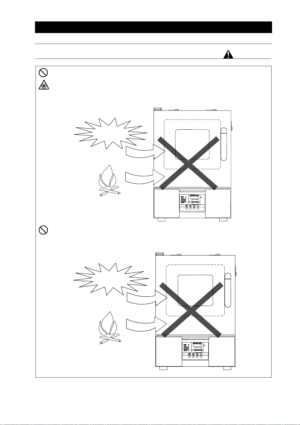
Warning・Cautions .........................................................................................................................3
2. Before operating the unit..............................................................................................................4
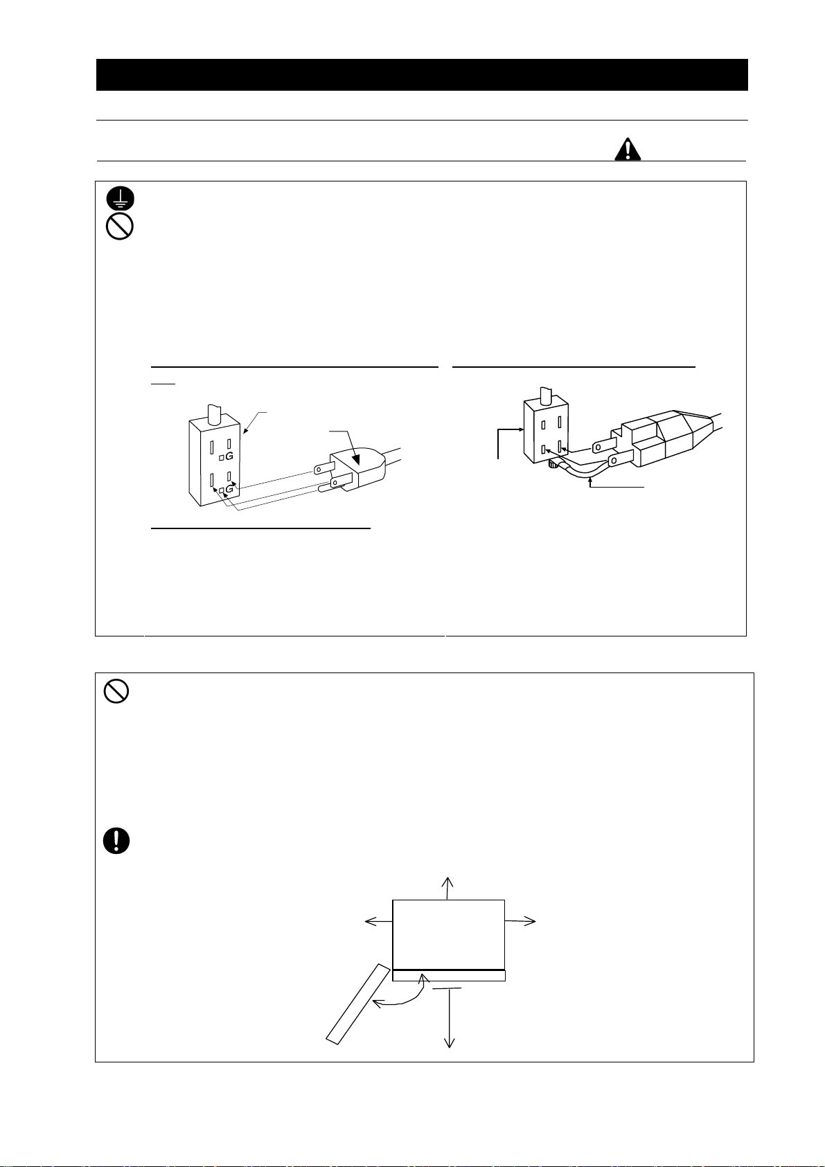
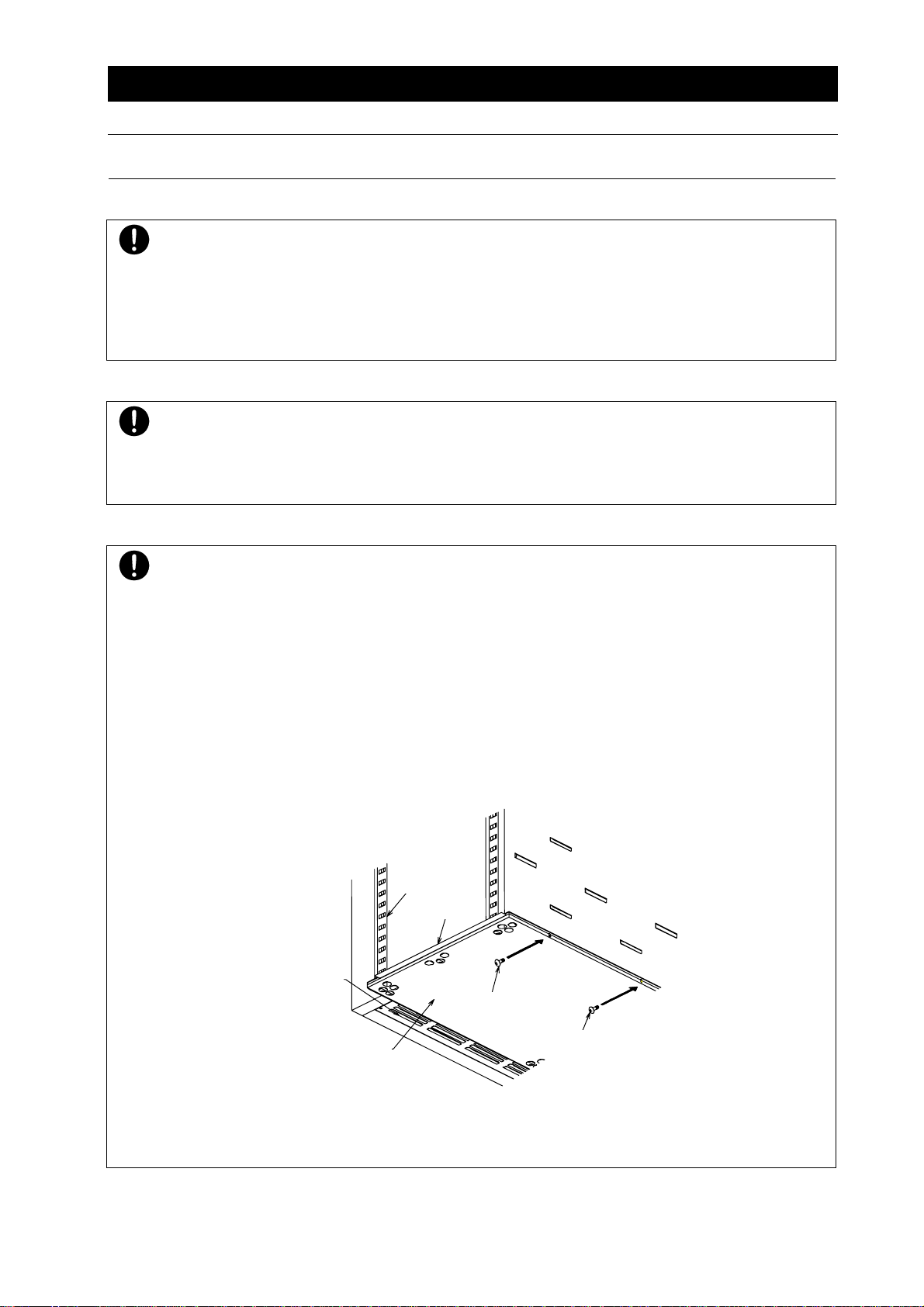
Precautions when installing the unit ................................................................................................4
3. Names and functions of parts ......................................................................................................9
Main body........................................................................................................................................9
Operation panel.............................................................................................................................10
Explanation of characters ..............................................................................................................11
4. Operating procedures.................................................................................................................13
List of operation modes and functions...........................................................................................13
Operation mode・function setting keys and characters ................................................................15
Settings for overheat prevention device ........................................................................................16
Operating procedures (fixed temperature operation).....................................................................17
Operating procedures (quick auto stop operation) ........................................................................18
Operating procedures (auto stop operation)..................................................................................19
Operating procedures (auto start operation)..................................................................................21
Preparing a program......................................................................................................................23
Program repeat operation..............................................................................................................28
Programming sheet .......................................................................................................................29
Useful functions (calibration offset function) ..................................................................................31
Useful function (lock function) .......................................................................................................32
5. Cautions on handling..................................................................................................................33
6. Maintenance procedures ............................................................................................................35
Daily inspection/maintenance........................................................................................................35
7. When the unit is not used for a long time or when disposing.................................................36
When the unit is not used for a long time or when disposing.........................................................36
Notes about disposition .................................................................................................................36
8. Troubleshooting ..........................................................................................................................37
Safety device and error codes.......................................................................................................37
When a malfunction is suspected..................................................................................................38
9. After sales service and warranty................................................................................................39
When requesting a repair ..............................................................................................................39
10. Specifications ............................................................................................................................40
11. Wiring diagram...........................................................................................................................41
12. List of replacement parts..........................................................................................................42
13. List of dangerous materials......................................................................................................43
14. Standard installation manual....................................................................................................44

1
1. Safety precautions
Explanation of Symbols
A variety of symbols are indicated in this operating instruction and on products to assure
safe operation. Possible results from improper operation ignoring them are classified as
follows.
Be sure to fully understand the descriptions below before proceeding to the text.
Warning Indicates a situation which may result in death or serious injury
(Note 1)
Caution Indicates a situation which may result in minor injury (Note 2) and
property damage (Note 3).
(Note 1) Serious injury means a wound, an electrical shock, a bone fracture or intoxication
that may leave after effects or require hospitalization or outpatient visits for a long
time.
(Note 2) Minor injury means a wound or an electrical shock that does not require
hospitalization or outpatient visits for a long time.
(Note 3) Property damage means damage to facilities, devices and buildings or other
properties.
This symbol indicates a matter that encourages the user to adhere to warning
(“caution” included).
Specific descriptions of warnings are indicated near this symbol.
This symbol indicates prohibitions
Specific prohibitions are indicated near this symbol.
This symbol indicates matters that the user must perform.
Specific instructions are indicated near this symbol.
About Symbols
Meanings of pictograms

2
1. Safety precautions
List of symbols
Warning
General warnings Danger!
High voltage
Danger!
High temperature
Danger!
Moving part
Danger!
Hazard of explosion
Caution
General cautions Electrical shock! Burning! Caution for no
liquid heating!
Caution for water
leak!
For water only Poisonous
material
Prohibitions
General bans Fire ban Do not
disassemble Do not touch
Compulsions
General
compulsions
Connect ground
wire Install levelly Pull out the power
plug
Regular
inspection

3
1. Safety precautions
Warning・Cautions
Warning
Never operate the unit in an atmosphere containing flammable or explosive gas
Never operate the unit in an atmosphere containing flammable or explosive gas.
Otherwise, an explosion or a fire may result since the unit is not explosion-proof.
See section “13. List of dangerous materials” on page 43.
Be sure to connect the ground wire.
Be sure to connect the ground wire correctly. Otherwise, electrical leak may result and cause
an electrical shock or a fire.
Ban on operation when an abnormality occurs
When a smoke or an unusual odor is seen or sensed, immediately turn the power switch on the
main unit off and pull out the power cord (plug) from the power supply. A fire or an electrical
shock may result.
Never use electrical power cords bundled.
When these are used bundled, they might overheat causing a fire.
Take care not to damage electrical power cords.
Avoid tightly bend; pull with a strong force or twist to prevent electrical power cords from
damaging. A fire or an electrical shock may result.
Never use an explosive or a flammable material with this unit.
Never use an explosive material, a flammable material or a material containing them. An
explosion or an electrical shock may result.
See section “13. List of dangerous materials” on page 43.
Never try to touch a hot part.
Some parts of the unit are hot during and immediately after operation. Take special care for
possible burning.
Never try to disassemble or alter the unit.
Never try to disassemble or alter the unit. A malfunction, a fire or an electrical shock may
result.
Caution
When a thunder is heard.
When a thunder is heard, turn the main power off immediately. A malfunction, fire or an
electrical shock may result.

4
2. Before operating the unit
Precautions when installing the unit
Warning
1. Be sure to connect the ground wire.
・ The DS402C/602C types use a single-phase 115V, DVS412C/612C types use a
single-phase 220V power source. Please consult your local electrical contractor for
power connecting work.
・ Be sure to connect the ground wire (green core wire of the power cord) to the ground
wire or the ground terminal in order to prevent an electrical shock from electric leakage.
・ Never connect the ground wire to gas or water pipes. Otherwise, a fire may result.
・ Never connect the ground wire to the ground for telephone wire or lightning conductor.
Otherwise, a fire or an electrical shock may result.
・ Do not use a branching receptacle, which may generate heat and possible danger.
We recommend use of a ground type outlet
tap.
When there is no ground terminal.
●In this case, class 3 grounding work is
necessary and please consult your dealer
or our nearest sales office.
When a bipolar type outlet tap is used
●Insert the ground adaptor included as an
option, into a power plug confirming the
polarity of the outlet. Connect the
grounding wire (green) of the ground
adaptor to the ground terminal on the
power supply equipment.
2. Carefully select an installation site.
Take special care not to install the unit at a place described below:
・ On uneven or dirty floor
・ Where combustible gas or corrosive gas exists
・ Where the ambient temperature is 35℃or more
・ Where temperature widely fluctuates
・ Where there is excessive dust or humidity
・ Where subject to direct sunlight
・ Where vibration is severe
Install this unit at a place with spaces shown below.
Do not cover the exhaust ports on the top of the unit.
15 cm
or more 15 cm
or more
Front
15 cm or more
1m or
more
Grounded
tap
Power plug
Bipolar outlet
tap
Ground wire

5
2. Before operating the unit
Precautions when installing the unit
Warning
3. Never operate the unit in an atmosphere containing explosive or flammable gas
Never operate the unit in an atmosphere containing flammable or explosive gas. Since the
unit is not explosion-proof, an arc is discharged when turning a switch “ON” and “OFF” and
during operation and a fire or an explosion may result.
See the section “13. List of dangerous materials” on page 43 for flammable and explosive
gases.
Never use the unit with an explosive material, a flammable material or a material containing
them. An explosion or a fire may result.
See the section “13. List of dangerous materials” on page 43 for flammable and explosive
substances.
Explosive
gas
Combustible
gas
Explosive
substance
Combustible
substance

6
2. Before operating the unit
Precautions when installing the unit
Warning
4. Do not alter the product. 5. Install the unit on a level surface
The user shall never attempt to alter the
unit since it may cause a malfunction.
Fla
t
Install the unit on a level surface.
Installing this unit on a slope might cause
unexpected troubles or malfunctions.
6. Do not overload shelves.
7. Do not place too many samples.
Withstand load of each shelf board is
15kg in uniform loading. Place samples
in a dispersed fashion.
Too many samples may prevent proper
temperature control. Be sure to use
shelf boards and place samples apart
each other so as to make free space of
30% or more to assure proper
temperature accuracy.
Shelf board
Sample
15 kg
Make at least 30% of space
Alteration

7
2. Before operating the unit
Precautions when installing the unit
Caution
8. Be sure to connect the power plug to the dedicated wall outlet.
Use a power distribution panel or a wall outlet that meets the electrical capacity of the unit.
Electric capacity: DVS402C AC115V 11.5A DVS412C AC220V 6.75A
DVS602C AC115V 13.1A DVS612C AC220V 7.25A
When the unit will not start even when you turn the power switch to “ON”, check for low
main voltage or if the unit is connected to the same power supply line as other devices and
connect it to another line if necessary.
9. Installation
The unit might fall down or move by an earthquake or an impact resulting to a personal
injury.
We recommend making safety measures such as to avoid installing the unit at a place
other than busy places.
Also, take appropriate safety measures to prevent the unit from tripping over.
10. Placing shelf boards and samples
Two shelf boards are included with this product.
One of them has been fixed on the lowest stage of the shelf pillar of the internal bath at the
time of shipping from the factory.
Set another board to an appropriate position in the bath.
A heater is installed under the flow adjusting board. Thus, the temperature of the flow
adjusting board and around it is always higher than the set temperature and placing a
sample directly on the board may damage it or cause a fire.
Therefore, the shelf board is fixed with screws as shown to disable direct placement of
samples.
Because of the shape of samples, when the unit is operated with shelf boards removed to
accept them, assure sufficient space between them and the flow adjusting board and never
place samples directly on the flow adjusting board.
Shelf pillar
Flow adjusting
board
Clamp
Screw
Screw
Shelf board

8
2. Before operating the unit
Precautions when installing the unit
Caution
11. About handling of the power cord
Never use electrical power cords bundled. When these are used bundled, they might
overheat causing a fire.
Do not convert, forcibly bend, twist or pull the power cord. Otherwise, a fire or an
electrical shock may result.
Do not place the power cord under a desk or a chair, or sand between objects to avoid it
from being damaged.
Do not place the power cord close to a stove or other heat generating device. Sheath of
the cord may burn and result in a fire or an electrical shock.
If the power cord should be damaged (exposure of core wire or disconnection),
immediately turn the main unit off, pull out the power cord (plug) out of the power supply
and ask your dealer to replace the cord. Otherwise, a fire or an electrical shock may
result.
Connect the power cord to an appropriate wall outlet.
12. When you operate the unit for the first time
When you operate the unit for the first time at a higher temperature, the unit may generate
an odor. This is due to decomposed bonding material contained in heat-insulation
material and is not a malfunction of the unit. We recommend operating the unit at the
highest temperature once before starting its regular operation.

9
3. Names and functions of parts
Main body
Front view
DVS412C/612C
Rear View
Control panel
Door
Handle
Power switch(ELB)
Power cord
Exhaust port
Cable hole
Observation window
Caution plate
Rating plate

10
3. Names and functions of parts
Operation panel
MEASURED TEMP.
℃
HEATER
ALARM
AUTO STOP
AUTO START
ENTER
SET
TEMP.
OVER TEMP.
PROTECTOR
FIXED TEMP.
RUN
STOP
SUB
MENU
TIMER
FIXED
TEMP. PROGRAM
PROGRAM
No. Name Operation/action
①RUN/STOP key Used for starting/stopping operation
②▲▼ keys Used for selecting settings.
③ENTER key Used for determining a selected setting.
④FIXED TEMP. key Key for selecting fixed temperature operation.
⑤TIMER key Key for selecting timer operation.
Quick auto stop operation, auto stop operation or auto start
operation can be selected.
⑥PROGRAM key Used for selecting programming and starting the program operation.
Programs of six patterns in three types can be set.
⑦SUB MENU key Key for setting temperature of the overheat prevention device,
calibration offset temperature, the key lock function or the program
repeat function.
⑧HEATER lamp Illuminates while heater power is on.
⑨ALARM lamp When an error occurs, the lamp illuminates with an audible buzzer.
⑩AUTO STOP lamp Flashes while the quick auto stop timer is being set and illuminates
while the unit is in operation.
Flashes while the auto stop timer is being set and illuminates while
the unit is in operation.
⑪AUTO START lamp Flashes while the auto start timer is being set and illuminates while
the unit is in operation.
⑫FIXED TEMP. lamp Flashes while fixed temperature operation is being set and
illuminates while the unit is in operation.
⑬PROGRAM lamp Flashes while the program operation is being set and illuminates
while the unit is in operation.
⑭MEASURED TEMP.
display
Displays measured temperature in the bath・set characters・alarm
information.
⑮SET TEMP. display Displays a set temperature, timer settings and timer remaining time.
⑯OVER TEMP.
PROTECTOR display
Displays the set temperature for the overheat prevention device.
①
⑦
⑯
⑮
⑭
⑧
⑨
⑩
⑪
⑫
③
②
④
⑥⑤
⑬

11
3. Names and functions of parts
Explanation of characters
Characters on the VS4 type controller are explained in this section.
Characters Identifier Name Application
Fix Fixed temperature
operation setting
Means settings for fixed temperature
operation.
Sv Temperature setting Used for setting a temperature.
AStP Auto stop setting Used for setting auto stop operation.
AStr Auto start setting Used for setting auto start operation.
tim Time setting Used for setting a time.
PrG3 Program type select
Used for selecting a program type 1,
2 or 3 to be used.
See section “Preparing a program on
page 23.
PAt Program pattern select
Used for selecting a program pattern
to be used.
See section “Preparing a program on
page 23.
End Time up
Displayed when timer operation has
ended.
See page 18, 19, and 21.
Sv-1 Program temperature
setting
Used for setting temperatures for
each step of a program.
(Sv-1 to Sv-30 is displayed.)
t-1 Program time setting
Used for setting time for each step of
a program.
(t-1 to t-30 is displayed.)
PS-3
Program repeat
Selecting a return
destination
Used for selecting a step for returning
during program repeat operation.
See section “Program repeat
operation” on page 28.
Pc-2 Setting number of
program repetitions
Used for setting number of program
repeat operations.
See section “Program repeat
operation” on page 28.

12
3. Names and functions of parts
Explanation of characters
Characters Identifier Name Application
cAL Calibration offset setting
Used for inputting a calibration offset
temperature
See section “Using the calibration
offset function” on page 31.
oH
Setting overheat
protection device
temperature
Used for setting an overheat
protection device temperature.
See section “Settings for overheat
prevention device” on page 16.
Lock Key lock of settings
Key locks settings to prevent their
alteration
See section” Using” on page 32.
* See the section “Operation mode・function setting keys and characters” on page 15 for
characters of operation modes and functions
.

13
4. Operating procedures
List of operation modes and functions
Operation modes of the unit are as shown below:
№Name Description Page
1 Fixed temperature
operation
Pressing the FIXED TEMP. key to enter the fixed
temperature operation setting mode.
Pressing the FIXED TEMP. key again to enter the
temperature setting mode.
Set a temperature with the ▼▲ keys.
Pressing the RUN/STOP key to start operation,
and pressing the RUN/STOP key again to stop operation.
P. 1 7
2 Quick auto
stop operation
Used when you want to, for example, “stop operation being
performed automatically in several hours.
Pressing the TIMER key during the fixed temperature
operation to enable setting a time before operation stops.
Set duration before stop with the ▼▲ keys.
Pressing the RUN/STOP key starts quick auto stop operation
and activates the timer in the middle of it to automatically
stop it after the set period of time.
P. 1 8
3 Auto stop operation
Used when you want to “set automatic stop for fixed
temperature operation when making settings for it.”
Press the TIMER key to display “AStP.”
Pressing the ENTER key to set the temperature setting “Sv.”
Pressing the ENTER key again to enable setting of the
operation time “tim.”
Pressing the RUN/STOP key starts auto stop operation.
P. 1 9
4 Auto start operation
Used when you want to “start operation automatically after
several hours” after power is turned on.
Press the TIMER key to display “AStr.”
Pressing the ENTER key to set the temperature setting “Sv.”
Pressing the ENTER key again to enable setting of the
operation time “tim.”
Pressing the RUN/STOP key starts auto start operation.
P. 2 1
5 Program operation
This is used to raise or lower temperature based on the set
temperature and time.
Press the PROGRAM key to display “PrGn.” (n:1,2,3)
Press the PROGRAM key again to select a program mode
you want.
To select “PrG2” or “PrG3”, press the ENTER key to select a
pattern “PAt” you want.
Pressing the RUN/STOP key starts program operation.
P. 2 3
* Operation mode cannot be changed while the unit is in operation. First stop operation before
changing the mode.

14
4. Operating procedures
List of operation modes and functions
Operating functions of the unit are as shown below:
№Name Description Page
1 Overheat prevention
function
Automatic overheat prevention function:
This function is linked to the unit set temperature and
has been set to so that it is automatically activated
(returned automatically) at a temperature 12℃higher
than the set temperature in the bath.
Overheat prevention device:
Although the power supply, the display and the key input
assembly are in common with the controller, the device
consists of the standalone temperature measurement
circuit, the CPU, the sensor, and the output circuit
enabling to set to a temperature you want on the
operation panel.
If the overheat prevention device is triggered, the unit will
stop and will not recover until the power switch is turned
on again. (Manual recovery)
P. 1 6
2 Calibration offset
function
Calibration offset function compensates any differences
between the target temperature in the bath and the control
temperature of the controller (sensor temperature.)
The function can compensate to either plus or minus side
for the whole temperature band of the unit.
P. 3 1
3
Overheat prevention
temperature
compensation function
When temperature compensation in item two is made for
the controller, temperature to be input to the overheat
prevention device will also be compensated automatically.
-
4 Power outage
compensation function
When power outage occurs in the middle of operation, the
operation resumes from the status immediately before the
power outage.
-
5 Setting lock function This function locks the set operation status.
The lock can be set or released with the SUB MENU key. P. 3 2

15
4. Operating procedures
Operation mode・function setting keys and characters
Key operations and characters in the diagram below are used for operation mode and function settings.
ELB ON
Fixed temp.
operation
FIXED
TEMP
Sv
RUN/
STOP
Temp. setting
Timer
operation
Setting overheat
prevention device Calibration offset function
▲▼
TIMER
TIMER
Fixed temp.
operation
Quick/auto stop Auto start
One
sec.
RUN/
STOP
Sv
▲▼
Temp. setting
tim
Time setting
▲▼
ENTER
One
sec.
Operation
start Auto start of
operation
▼ ▲
Setting overheat
prevention device
temp.
▼ ▲
Setting
compensation
temp.
PlusMinus
SUB
MENU
Operation
start
TIMER
TIMER
Timer start
▼ ▲ ▼ ▲
SUB
MENU
FIXED
TEMP.
Auto stop
▲▼
tim
Time setting
AStP
ENTER
Sv
▲▼
Temp. setting
tim
Time setting
▲▼
One
sec.
TIMER
AStr
Automatic
stop of
operation
oH
ENTER
cAL
PRO-
GRAM
Programming
PRO-
GRAM
Program 1 Program 2 Program 3
ENTER
PrG1
30 steps x 1 pattern
PrG3
10 steps x 3 patterns
PrG2
15 steps x 2 patterns
Setting no. of
program steps
End
▲
▼
Sv-1
▲▼
Program mode
setting
Step 1
Temp. setting
t-1
▲▼
Step 1
Time setting
Press to switch
Temp. and time
are set in turn
for each step
ENTER
Program operation
start
SUB
MENU
SUB
MENU
PS-n
▼ ▲
Setting step No.
to return
SUB
MENU
Pc-n
▼ ▲
Setting no. of
step repetitions
Program repeat
operation
PAt
Program pattern
select
▲
▼
Setting no. of
program steps
End
▲▼
Sv-1
▲▼
Step 1
Temp.setting
t-1
▼ ▲
Step1
Time setting
Temp. and time
are set in turn
for each step
Program repeat
operation
(same as left)
Lock function
▼ ▲
Lock setting
ENTER
OFF
ON
▼ ▲
SUB
MENU
Lock
Operation
start
One
sec.
RUN/
STOP RUN/
STOP
RUN/
STOP
RUN/
STOP
PRO-
GRAM
Program
operation
PRO-
GRAM
Program 1 Program 2 Program 3
PrG1
30 steps x 1 pattern
PrG3
10 steps x 3 patterns
PrG2
15 steps x 2 patterns
Program mode
select
Press to switch
ENTER
PAt
Program pattern
select
▲
▼
RUN/
STOP
Operation
start
RUN/
STOP
Operation
start
ENTER
ENTER
ENTER ENTER
ENTER
ENTER
ENTER
ENTER
ENTER
ENTER
ENTER ENTER
ENTER
ENTER
ENTER
ENTER
ENTER

16
4. Operating procedures
Settings for overheat prevention device
The safety device for preventing overheat has the automatic overheat prevention function for the
controller (automatic recovery) and has the power supply, the display and the key input assembly in
common with the controller as well as it has an overheat prevention device (manual recovery) as a
secondary safety measures that consists of separate temperature measurement circuit, the CPU,
the sensor and the output circuit.
Temperature setting range and functions
The device has overheat prevention function in double. One is the function integrated in the
controller, which is designed to be activated automatically at a temperature 12℃above the set
temperature of the temperature controller (the heater repeats ON/OFF at +12℃) at the time of
shipping from the factory.
Another is integrated with the controller and is set with the keys on the controller.
The secondary overheat prevention function is added by this setting.
The temperature range settable for the overheat prevention device integrated with the controller is
“0℃to the 50℃+ the highest set temperature for the device.”
When the temperature in the bath keeps rising beyond the controller set temperature and reaches
the set temperature of the overheat prevention device, the circuit trips, Er19 flashes on the controller
screen, and the buzzer continues to sounds.
When the overheat prevention device is activated, it will not be released until power is turned on and
Er19 will not be released.
How to set temperature 1. Turn power ON. (Turn the ELB to ON.)
When power is turned ON, the initial values will be displayed
for about four seconds, then the initial screen will appear and
the current bath temperature, operation mode character and
the overheat prevention set temperature are displayed on
each of the displays.
MEASURED TEMP.
℃
HEATER
ALARM
AUTO STOP
AUTO START
ENTER
SET
TEMP.
OVER TEMP.
PROTECTOR
FIXED TEMP.
RUN
STOP
SUB
MENU
TIMER
FIXED
TEMP. PROGRAM
PROGRAM
MEASURED TEMP.
℃
HEATER
ALARM
AUTO STOP
AUTO START
ENTER
SET
TEMP.
OVER TEMP.
PROTECTOR
FIXED TEMP.
RUN
STOP
SUB
MENU
TIMER
FIXED
TEMP. PROGRAM
PROGRAM
2. Setting the overheat prevention temperature
① Press the SUB MENU key.
② Press the ▼▲ keys to select the overheat prevention
temperature setting character oH for the
MEASURED TEMP. display.
③ Pressing the ENTER key displays the current set
temperature flashing on the SET TEMP. display.
Caution: In general, set to a temperature at least 10℃
higher than the controller set temperature to
prevent the device from malfunctioning.
④ When the temperature you want is obtained with the ▼▲
keys, press the ENTER key to complete setting.
Caution
① Set temperature as “highest operation temperature for the unit +20℃” or “set temperature
+20℃” as a rough standard and add 5℃to the setting if the device functions improperly.
② Be sure to set the overheat prevention activation temperature correctly otherwise the device
may not start, the overheat prevention device is activated before temperature in the bath
increases completely, or a fire or other unexpected accidents may result.
The temperature is set at 290℃on shipping from the factory.
③ The overheat prevention device has been designed to prevent overheating of devices not to
protect samples. The device does not prevent accidents caused from use of explosive or
flammable materials.
①
②
③
④
④

17
4. Operating procedures
Operating procedures (fixed temperature operation)
How to start fixed
temperature
operation
MEASURED TEMP.
℃
HEATER
ALARM
AUTO STOP
AUTO START SET
TEMP.
OVER TEMP.
PROTECTOR
FIXED TEMP.
PROGRAM
1. Turn power ON. (Turn the ELB to ON.)
When power is turned ON, the initial values will be displayed for
about four seconds, then the initial screen will appear and the
current bath temperature, operation mode character and the
overheat prevention set temperature are displayed on each of the
displays.
MEASURED TEMP. display: Indicates the present bath temperature and various
characters.
Set temperature display: Indicates the set temperature and various characters.
Overheat prevention set temperature display: Indicates the set temperature for
the overheat prevention device.
For operation mode characters, see section page 11.
MEASURED TEMP.
℃
HEATER
ALARM
AUTO STOP
AUTO START
ENTER
SET
TEMP.
OVER TEMP.
PROTECTOR
FIXED TEMP.
RUN
STOP
SUB
MENU
TIMER
FIXED
TEMP. PROGRAM
PROGRAM
MEASURED TEMP.
℃
HEATER
ALARM
AUTO STOP
AUTO START
ENTER
SET
TEMP.
OVER TEMP.
PROTECTOR
FIXED TEMP.
RUN
STOP
SUB
MENU
TIMER
FIXED
TEMP. PROGRAM
PROGRAM
MEASURED TEMP.
℃
HEATER
ALARM
AUTO STOP
AUTO START
ENTER
SET
TEMP.
OVER TEMP.
PROTECTOR
FIXED TEMP.
RUN
STOP
SUB
MENU
TIMER
FIXED
TEMP. PROGRAM
PROGRAM
2. Selecting an operation mode
Press the FIXED TEMP. key to display the fixed temperature
operation mode on the SET TEMP. display.
Display the character Fix .
3. Setting the temperature
Press the FIXED TEMP. key again.
The character SV that indicate a set temperature is
displayed on the MEASURED TEMP. display on which the current
set temperature flashes and the FIXED TEMP. lamp flashes.
Set a temperature using the ▼▲ keys.
4. Starting operation
Press the RUN/STOP key for about one second. Operation starts
and status of the FIXED TEMP. lamp changes from flashing to
illuminated.
5. Stopping operation
Press the RUN/STOP key for about one second. Operation stops,
the FIXED TEMP. lamp goes off and the screen switches to the initial
setting screen.
When you want to
correct setting
errors or confirm
settings
When you made a mistake during setting or reconfirm settings you
made, press the FIXED TEMP. key again to resume setting.
When you want to change set temperature during operation, press the
FIXED TEMP. key to enter the setting mode and change the set
temperature. After change has been made, press the ENTER key to
complete the process.

18
4. Operating procedures
Operating procedures (quick auto stop operation)
Procedures for quick
auto stop operation
Used when you want to, for example, “stop fixed temperature
operation being performed automatically in several hours. Quick auto
stop operation is a function to enable auto stop timer setting during
operation.
MEASURED TEMP.
℃
HEATER
ALARM
AUTO STOP
AUTO START
ENTER
SET
TEMP.
OVER TEMP.
PROTECTOR
FIXED TEMP.
RUN
STOP
SUB
MENU
TIMER
FIXED
TEMP. PROGRAM
PROGRAM
1. Setting time period before stop during fixed temperature
operation
Make sure that the FIXED TEMP. lamp is illuminated to indicate the
unit is the fixed temperature operation mode.
Press the TIMER key.
The character tim that indicates the timer is displayed on
the MEASURED TEMP. display and the current set time flashes on
the SET TEMP. display.
Set a time you want using the ▼▲ keys.
About the timer function
The maximum time that can be set for the timer is 999 hours 50
minutes.
Up to 99 hours 59 minutes, time can be set in minutes.
One hundred hours and over are set only in 10 minutes.
Keep the ▼▲ keys pressed to continuously change set time and you
can quickly reach the time you want. Press the ▼▲ keys once at a
time for fine adjustment.
MEASURED TEMP.
℃
HEATER
ALARM
AUTO STOP
AUTO START
ENTER
SET
TEMP.
OVER TEMP.
PROTECTOR
FIXED TEMP.
RUN
STOP
SUB
MENU
TIMER
FIXED
TEMP. PROGRAM
PROGRAM
2. Starting timer operation
When you have set a time you want, start the RUN/STOP key for
about one second. Timer operation starts with the FIXED TEMP.
lamp and the AUTO STOP lamp are illuminated. Timer starts
counting when the RUN/STOP key is pressed.
3. Stopping and ending timer operation
Operation stops automatically when the set time comes.
The buzzer sounds for about five seconds to indicate operation has
stopped. At this time, the character End that indicates
operation end is displayed on the SET TEMP. display with the
FIXED TEMP. lamp and the AUTO STOP lamp are illuminated.
Press the RUN/STOP key for approx. one second to end the timer
operation mode. The screen switches to the initial setting screen.
When you want to
correct set
temperature or set
time, or confirm
settings
When you want to change set temperature during operation, press the
FIXED TEMP. key to enter the setting mode and change the set
temperature. After change has been made, press the ENTER key to
complete the process. When you want to change set time during
operation, press the TIMER key to enter the setting mode and change
the set time. Note, however, you need to set a time calculated by
adding the time already passed to the time to be added. After
change has been made, press the RUN/STOP key to complete the
process.
Pressing the ▼key will display the set temperature, the operation
mode and the remaining time on the SET TEMP. display.
This manual suits for next models
3
Table of contents
Other Yamato Oven manuals

Yamato
Yamato DPC Series User manual

Yamato
Yamato DR 200 User manual

Yamato
Yamato DNF 400 User manual

Yamato
Yamato DG-440C User manual

Yamato
Yamato DKN302C User manual

Yamato
Yamato DX302C User manual

Yamato
Yamato DNF301 DNF401 User manual

Yamato
Yamato DNF811 User manual

Yamato
Yamato DX302 User manual

Yamato
Yamato DS 400 User manual
Popular Oven manuals by other brands

Middleby Marshall
Middleby Marshall PS300F Owner's operating & installation manual

Kleenmaid
Kleenmaid TO56X owner's manual

Fulgor Milano
Fulgor Milano F1SP24 1 Series Use & care manual

Rommelsbacher
Rommelsbacher BGE 1580/E instruction manual

GE
GE Trivection JT930 installation instructions

S+ARCK
S+ARCK Gorenje BO658ST Detailed instructions for use