YAMIT E.L.I. AF800N Series User manual

Table of Contents
Subject Page No.
1.
Introduction
3
2.
Safety Instruction
3
3.
Description & Operation
4
4.
Technical
Data
5
5.
Initial Installation & Operation
8
6.
Maintenance &
Periodical Checks
10
6.1
6V (4X1.5V) Batteries Removal and Installation
10
6.2
Control Card Removal and Installation
11
6.3
Solenoid Removal and Installation
13
6.4
Hydraulic Piston Assembly Removal and Installation
14
6.5
Coarse Screen Removal and Installation
15
6.6
Fine Screen Assembly Removal and Installation
16
6.7
Dirt Collector Removal and Installation
18
6.8
Periodical Checks
20
7.
Troubleshooting
22
8.
IPB
27
9.
Appendix
33
9.1
Filtron
1-10 (DC/AC)
33
9.2
Control Loops Schematic Drawing
38
10.
International Warranty
40
ALL RIGHTS RESERVED, THIS MANUAL AND THE INFORMATION CONTAINED ARE NOT ALLOWED
TO BE USED WITHOUT WRITTEN PERMISSION FROM YAMIT Filtration & Water Treatment Ltd.
AF800N

1. Introduction
General
YAMIT Filtration Ltd congratulates you on purchasing the AF800N SERIES self-
cleaning filter. This filter is part of the wide family of filters produced and
supplied by YAMIT for agriculture, municipal water and sewage systems, and
all types of industrial applications. All products manufactured by YAMIT are
easy to install, use and service and don’t require special skills to operate them.
For operation and maintenance of the filter please follow the instructions in
this manual.
2. Safety Instructions
1. Prior to installation or handling of the filter, read carefully the installation
and operation instructions carefully.
2. Confirm filter draining prior to service.
3. Take precautions while lifting, transporting or installing the filter.
4. Installation of the filter should be performed so as to avoid direct water
splashing on any of the filter parts and especially on the electronic control
unit.
5. Confirm that filter weight, when full, meets the support construction
requirements.
6. Prior to installation confirm that line pressure matches filter’s operational
pressure.
7. During installation, use standard flanges and connections only.
8. Check that all filter flange bolts are properly secured.
9. Please note, the filter enters a flushing mode automatically, without prior
warning.
10. Use original parts only when servicing the filter.
11.YAMIT can not accept responsibility for any changes or modifications to the
equipment.
3
2
1
AF800N

1. Inlet
2. Coarse screen
3. Fine screen
4. Flushing valve
5. Hydraulic piston
6. Hydraulic motor chamber
7. Dirt
collector
8. Suction nozzle
9. Hydraulic motor
10. Outlet
11. Electronic DP unit
12. control unit
13. Solenoid
valve
3. Description & Operation
Filter Assembly General Description (Figure 1)
The AF800N SERIES self-cleaning filter enables high quality filtration from
grades of 80-1000 micron from various types of fluid sources such as sewage,
reservoirs, rivers, lakes, and wells.
The AF800N SERIES filter contains the following parts:
Figure 1: Filter Assembly
4
3
AF800N

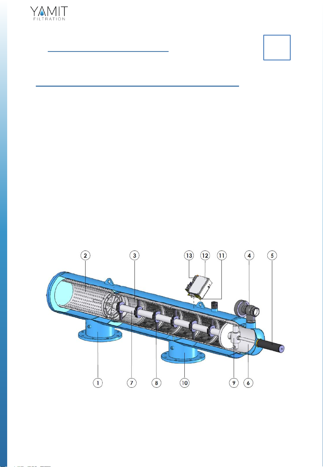
Filter Operation - General Description (Figure 1)
Water enters the filter through the “Inlet” (1) and passes through the coarse screen (2) that
functions as a “first stop” for rough particles. Water then reaches the fine screen (3), which
further purifies the flow by separating smaller particles from the water. As more water flows
through, impurities build up on the fine screen. As impurities on the screen accumulate, a
pressure imbalance is built up between the internal section of the fine screen (3) and its
external section. When the difference in pressure (DP) reaches the preset value in the
electronic control unit (12), a series of events is triggered while the water continues to flow
to the user. The flushing valve (4) opens, pressure is released from the hydraulic piston (5)
and water flows outside. Pressure in the hydraulic motor chamber (9) and the dirt collector
(7) is significantly lowered, and the dirt collector nozzles (8) begin a suction process. The
water flows through the hydraulic motor (9) which rotates the dirt collector (7) around its
axis. The pressure released from the piston (5) and the high pressure inside the filter cause
linear movement of the dirt collector. The combination of the linear movement and rotation
significantly cleans the entire internal screen (3) surface.
The flushing cycle takes about 10 seconds. The flushing valve (4) closes at the end of the
cycle and the increased water pressure returns the hydraulic piston (5) to its initial position.
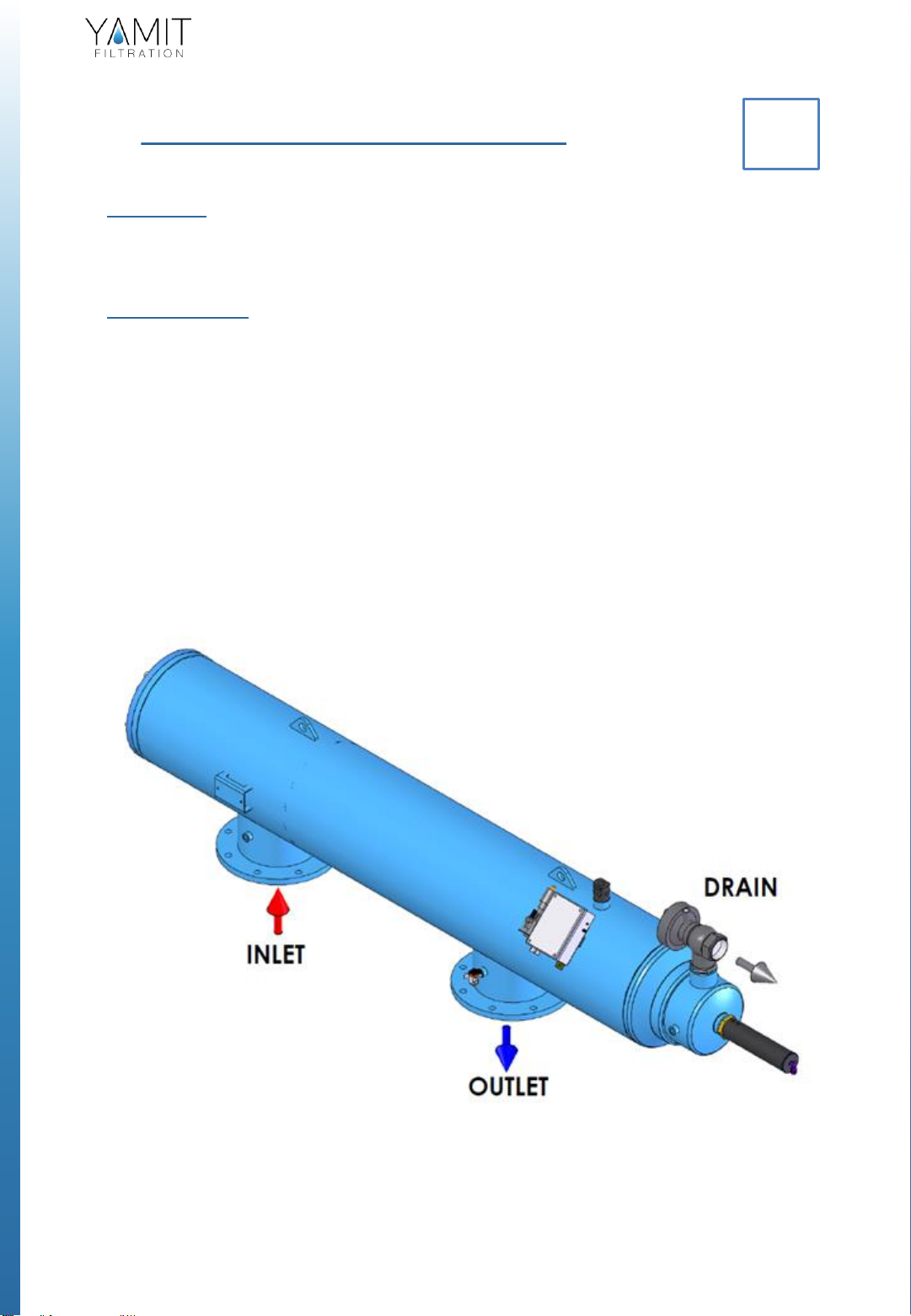
The filter is now ready for the next flushing cycle, with clean and filtered water flowing
through the “Outlet” (10).
Note: At the back of the piston is an indicator that pops up when the piston reaches the end
of its motion. –this indicator helps us to check whether the dirt collector, inside the filter,
completed it’s motion.
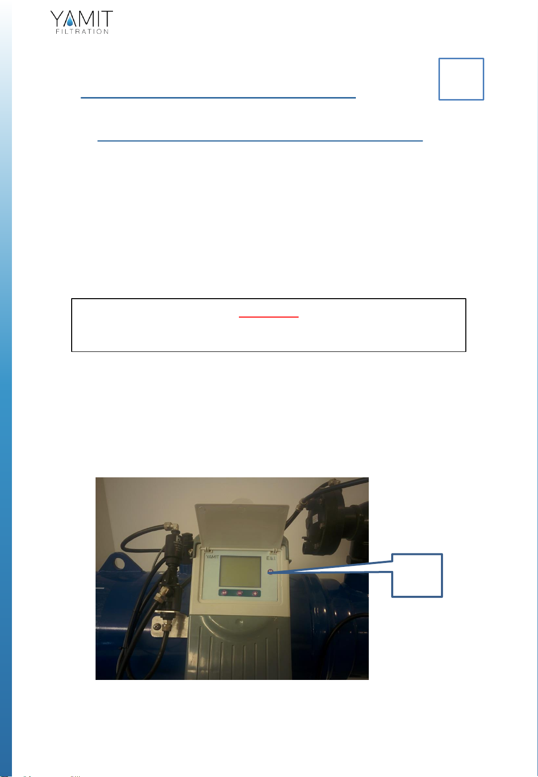
General Description of the Electronic Control System
The electronic system (12) initiates the cleaning process based on either time differential
(DT) and / or pressure indicator differential. The trigger closes a circuit and then triggers the
electronic control unit after a delay of 15 seconds. The electronic control unit (12) controls
the opening and the closing of the flushing valves (4) via the solenoid valve (13). The flushing
cycle, which takes a total of about 10 seconds (can be adjusted by the operator), resumes its
operation whenever the time cycle ends or the difference in pressure reaches the preset
pressure value set in the controller. If the difference in pressure remains unchanged after
one cycle, another cycle will start after a delay of 15 seconds.
.
Figure 1: Filter Assembly
5
AF800N

4. Technical Data
Standard Features
Minimum operating pressure: 2 bar (29 psi)
Maximum operating pressure: 10 bar (145 psi)
Clean filter pressure loss: 0.1bar (1.45 psi)
Maximum water temperature: 65°C (149°F)
Filtration range: 80-1000 microns
Control voltage: 6V 12V DC, 24V AC, 220V AC
Flush water consumption
(at minimum working pressure): 80 liters (21 gallons)
Filter housing materials: carbon steel coated with baked on epoxy
Measurements & Weight
6
X= Extra-long filter with extra-large filtration area
L= Long filter with large filtration area
* Flow rate data is for high quality water at filtration grade of 120 microns.
** Flushing flow rate data is for minimum operational pressure (2 bars / 29 psi).
4
Model
In/Outlet
D
(mm) (in)
D1
(in)
H
(mm)(in)
X
(mm) (in)
L
(mm) (in)
L1
(mm) (in)
L2
(mm) (in)
Weight
Package
(kg) (lb)
Volumen Package
LxAxH
(m) (ft)
AF803NL
75
3
10
545
21.4
450
17.7
1139
44.8
1386
54.6
2040
80.3
110
243
1.6x0.6x0.8
5.3x2.0x2.6
AF804NL
100
4
10
545
21.4
900
35.4
1535
60.4
1782
70.1
2820
111.0
135
298
1.9x0.6x0.8
6.6x2.0x2.6
AF804NX
100
4
10
545
21.4
900
35.4
1931
76.0
2178
85.7
3620
142.5
154
340
2.4x0.6x0.8
7.9x2.0x2.6
AF806NL
150
6
12
580
22.8
900
35.4
1605
63.2
1851
72.9
2890
113.8
147
324
1.9x0.6x0.8
6.6x2.0x2.6
AF806NX
150
6
10
555
21.8
900
35.4
2001
78.8
2247
88.5
3680
144.9
157
346
2.4x0.6x0.8
7.9x2.0x2.6
AF808NL
200
8
12
579
22.8
900
35.4
2190
86.2
2437
95.9
3870
152.4
187
412
2.6x0.6x0.8
8.5x2.0x2.6
AF810NL
250
10
14
595
23.4
900
35.4
2194
86.4
2437
96.1
3870
152.4
212
467
2.6x0.6x0.8
8.5x2.0x2.6
AF800N

Flow Rate
7
Filtration Grade Conversion Table
Micron
80 100
120
150
200
300
400
500
800
1000
Mesh
200
150
120
100
80 55 40 30 20 15
Pressure Loss at 120 micron
Model
In/Out
D
(mm) (in)
Maximum
Flow Rate
(m3/h) (gpm)
Screen area
(cm2) (in2)
Flushing
Flow Rate
(m3/h) (gpm)
Flushing volume
(m³) (gal)
AF803NL 75 350 220 3220 500 30 132 0.083 22.01
AF804NL 100 480 350 5780 895 30 132 0.083 22.01
AF804NX 100 4100 440 8410 1303
30 132 0.083 22.01
AF806NL 150 6150 660 5780 895 30 132 0.083 22.01
AF806NX 150 6160 700 8410 1303
30 132 0.083 22.01
AF808NL 200 8300 1320 8410 1303
30 132 0.083 22.01
AF810NL 250 10 400 1760 8410 1304
30 132 0.083 22.01
Pressure
(psi) (bar)
Flow
(m3/h)
(gpm)
AF800N

8
5. Initial Installation & Operation
General
The filter assembly is protectively packed with all parts assembled.
Installation
1. Remove the filter assembly from the wood platform.
2. Connect the filter assembly to the inlet line and outlet line.
3. Connect a drain pipe to the hydraulic flushing valve outlet opening (at
least 63 mm plastic pipe or 2" metal pipe and no more then 5 m long)
Confirm that water runs freely out of the drainpipe.
4. Check that all connections are properly secured.
5. Check that all nuts and bolts on the filter periphery are properly
tightened and secured.
6. Connect the batteries located in the control unit box as explained in
“Initial Operation” (See Figure 3).
Figure 2: Initial Filter Installation
5
AF800N

9
Initial Operation
1. Gradually open the inlet valve (make sure that the outlet valve, if
installed, is open).
2. Check the filter assembly and its connections for leaks.
Perform a flushing cycle manually by pushing the test button located on
the outside of the control box (See Figure 3).
3. Verify that the hydraulic piston fully extends during back flush.
4. Verify that the hydraulic flushing valve closes after 10 seconds.
5. When the filter is clean, verify that the differential pressure between
inlet and outlet does not exceed 0.1 bar.
6. Check that the differential pressure is set to 7 psi or 0.5 bar (5 meter) in
the controller (see Appendix 1).
Figure 3: Control Unit
AF800N

10
6. Maintenance & Periodical Checks
6.1 - 6V (4 x 1.5V) Battery Removal & Installation
The 4 x 1.5V battery enables the electronic control unit's operation. The
battery can last for 3000 flushing cycles, but should be replaced every six
months. Use ONLY ALKALINE type battery.
1. Remove the upper cover of the controller.
2. Disconnect and remove the used battery.
3. Connect a new battery according to the correct polarity. The controller
will perform long "beep" sound.
4. Close the upper cover.
5. Perform a flushing cycle by disconnecting the low pressure tube from the
differential pressure indicator (thereby closing the electrical circuit) –re-
connect it immediately as flushing starts.
6. Verify that the hydraulic flushing valve closes after 10 seconds.
7. Perform an additional flushing cycle manually by pushing the manual
bottom (M on the screen display). (See Figure 3).
WARNING
Take precautions while operating the filter as the filter may enter a flushing
mode automatically, without prior warning.
Figure 3: Battery Removal & Installation
6
M
AF800N

11
6.2 - Control Card Removal & Replacement
1. Disconnect the controller from power (AC) or remove batteries (DC)
2. Remove upper and lower cover. If there are any outputs card
connected to the controller disconnect them.
3. Unscrew 5 screws (Red Circles).
Disconnect power wires (Both AC & DC model - Blue Square)
Disconnect DP sensor, Pressure sensor and external DP (If exists -
Yellow Square)
4. Turn on back and separate the back cover:
DC MODEL AC MODEL
AF800N

12
5. For DC model only–Unscrew and remove step-up card
6. Unscrew the main card –4 screws (Red circles). Remove the card.
7. Place the new card and go backwards through the same steps as
described above:
•Fasten the 4 screws.
•Place the Step-up cards and fasten the screw (DC MODEL ONLY)
•Join the two plastic parts (Front and back) and turn to front.
•Connect DP sensor, Pressure sensor and external DP (If exists –
Yellow square)
•Connect power cable (Blue Square)
•Fasten the 5 screws (Red Circles)
•Reconnect the output cards to the controller. Reconnect solenoids (If
disconnected before)
•Return the upper and lower cover
•Connect to power.
AF800N

6.3 - Solenoid Removal & Replacement
The solenoid hydraulically controls the flushing valve's operation.
1. Remove the upper cove, disconnect and remove the 4 x 1.5V batteries.
2. Disconnect the solenoid control tubes.
3. Remove the fittings from the damaged solenoid.
4. Disconnect the electrical wiring from the control card terminals.
5. Remove the nut from the solenoid lower section.
6. Pull the solenoid out of the control assembly.
7. Insert a new solenoid into the control assembly.
8. Re-Install the nut on the solenoid lower section.
9. Install the fittings on the ports of the new solenoid.
10. Connect the 2 wires of the solenoid (black wire to "C" port, red wire to "1"
port).
11. Connect the solenoid control tubes
12. Connect the 4 X 1.5V batteries according to the correct polarity and close
the electronic control unit cover.
13. Perform a flushing cycle by disconnecting the low pressure tube from the
differential pressure indicator (closing of the electrical circuit) –re-connect
it immediately as flushing starts.
14. Verify that the hydraulic flushing valve closes after 10 seconds.
15. Perform an additional flushing cycle manually by pushing the manual
bottom (M on the screen display). (See Figure 3).
WARNING
Take precautions while operating the filter as the filter may enter a flushing
mode automatically, without prior warning.
13
Figure 5: Solenoid Removal & Replacement
AF800N

14
6.4 - Hydraulic Piston Assembly Removal &
Replacement
The hydraulic piston enables the linear movement of the dirt collector.
1. Close the inlet and the outlet line valves.
2. Verify that the filter is drained prior to service.
3. Disconnect the control tube from the piston assembly’s upper section.
4. Screw the brass base out (clockwise) of the filter body and carefully
remove the piston assembly.
5. Remove the O-ring from the current piston assembly.
6. Position the O-ring in the new piston assembly.
7. Lubricate the O-ring with silicon grease.
8. Carefully slide the new piston assembly into the filter housing.
9. Screw (counterclockwise) the brass base into the filter body and tighten it
gently.
10. Connect the control tube to the piston assembly’s upper section.
11. Open the inlet and the outlet line valves.
12. Check for leaks.
13. Push the piston indicator (on the rear side of the piston) inside.
Perform a flushing cycle manually by pushing the manual bottom (M on
the screen display). (See Figure 3).
14. Verify that the piston travels its complete path and that the indicator pops
up.
Verify that the hydraulic flushing valve closes after 10 seconds
WARNING
Take precautions while operating the filter as the filter may enter a flushing
mode automatically, without prior warning.
Figure 6: Piston Assembly Removal & Installation
AF800N

6.5 - Coarse Screen Removal & Installation
1. Close the inlet and the outlet line valves.
2. Verify that the filter is drained prior to service.
3. Remove the nuts and washers connecting the cover to the filter housing.
4. Remove the cover seal from the cover groove.
5. Pull out the damaged coarse screen out from the fine screen assembly
using the gripping handle.
6. Slide the new coarse screen into the fine screen assembly using the
gripping handle.
7. Verify that the straight side of the cover seal fits into the groove located in
the cover.
8. Put the cover on its place on the filter's housing and Install the nuts and
washers connecting the cover to the filter housing.
9. Open the inlet and outlet line valves.
10. Check for leaks.
11. Perform a flushing cycle manually by pushing manual bottom (M on the
screen display). (See Figure 3)
12. Verify that the hydraulic flushing valve closes after 10 seconds.
WARNING
Take precautions while operating the filter as the filter may enter a flushing
mode automatically, without prior warning.
15
Figure 7: Piston Assembly Removal & Installation
AF800N

16
6.6 - Fine Screen Assembly Removal & Installation
1. Close the inlet and the outlet line valves.
2. Verify that the filter is drained prior to service.
3. Remove the nuts and washers connecting the cover to the filter housing.
4. Remove the cover from the filter's housing and remove the cover seal from
the cover groove.
5. Pull out the coarse screen from the fine screen assembly using the gripping
handle.
6. Pull the fine screen assembly out of the filter housing assembly with the
dirt collector.
7. Remove both o-rings (445) from the current fine screen assembly.
8. Unscrew (clockwise - cw) the hydraulic motor from the dirt collector.
9. Unscrew (counterclockwise -ccw) the fine screen handle section from the
fine screen, loosen using screen wrenches.
10. Carefully pull the dirt collector out of the fine screen assembly.
11. Unscrew (ccw) the fine screen damaged sections and replaced them with
new sections.
12. Slide the dirt collector into the fine screen, through the dirt collector
bearing.
13. Position both o-rings (445) into the new fine screen assembly, if required
replace them.
14. Lubricate the o-ring (445) with silicon grease.
15. Screw (cw) the fine screen handle section to upper screen section; make
sure the dirt collector axis passes through the screen bearing. Tighten using
screen wrenches.
16. Screw (ccw) the hydraulic motor to the dirt collector.
17. Slide the new fine screen assembly into the filter housing assembly.
18. Slide the coarse screen into the fine screen assembly.
19. Verify that the straight side of the cover seal fits into the groove located in
the cover.
20. Put the cover on its place on the filter's housing and Install the nuts and
washers connecting the cover to the filter housing.
21. Open the inlet and the outlet line valves.
22. Check for leaks.
23. Perform a flushing cycle manually by pushing the manual bottom (M on
the screen display). (See Figure 3).
24. Verify that the hydraulic flushing valve closes after 10 seconds.
WARNING
Take precautions while operating the filter as the filter may enter a flushing
mode automatically, without prior warning.
AF800N

17
Figure 8: Fine Screen Assembly Removal & Replacement
AF800N

1818
6.7 - Dirt Collector Removal & Installation
1. Close the inlet and the outlet line valves.
2. Verify that the filter is drained prior to service.
3. Remove the nuts and washers connecting the cover to the filter housing.
4. Remove the cover from the filter's housing and remove the cover seal from
the cover groove.
5. Pull out the coarse screen from the fine screen assembly using the gripping
handle.
6. Pull the fine screen assembly out of the filter housing assembly with the
dirt collector.
7. Unscrew (clockwise - cw) the hydraulic motor from the dirt collector.
8. Unscrew (counterclockwise -ccw) the fine screen handle section from the
fine screen, loosen using screen wrenches.
9. Carefully pull the dirt collector out of the fine screen assembly.
10. Slide the new dirt collector into the fine screen, through the dirt collector
bearing.
11. Screw (cw) the fine screen handle section to upper screen section; make
sure the dirt collector axis passes through the screen bearing. Tighten using
screen wrenches.
12. Screw (ccw) the hydraulic motor to the dirt collector.
13. Slide the fine screen assembly into the filter housing assembly.
14. Slide the coarse screen into the fine screen assembly.
15. Verify that the straight side of the cover seal fits into the groove located in
the cover.
16. Put the cover on its place on the filter's housing and Install the nuts and
washers connecting the cover to the filter housing.
17. Open the inlet and the outlet line valves.
18. Check for leaks.
19. Perform a flushing cycle manually by pushing the manual bottom (M on
the screen display). (See Figure 3).
20. Verify that the hydraulic flushing valve closes after 10 seconds.
WARNING
Take precautions while operating the filter as the filter may enter a flushing
mode automatically, without prior warning.
AF800N

19
Figure 9: Dirt Collector Removal & Replacement
AF800N

20
6.8 - Periodical Checks
Perform yearly or periodical checks at the beginning of the season, according
to the following:
1. Replace the 4X1.5V batteries at the beginning of every season or every six
months; refer to "Batteries Removal & Replacement".
2. Check the condition of the coarse screen. If damaged, replace according to
"Coarse Screen Removal & Replacement”.
3. Check the condition of the fine screen assembly. If damaged, replace
according to "Fine Screen Assembly Removal & Replacement".
4. Check the condition of the dirt collector bearing and screen bearing. If any
of the bearings have become misshaped, (oval), replace with a new one.
5. Check the mechanical condition of the hydraulic piston assembly. Verify
piston’s free movement. If damaged or deteriorated, replace according to
"Hydraulic Piston Assembly Removal & Replacement".
6. Check the dirt collector suction nozzles height (see table). If damaged,
replace according to "Dirt Collector Removal & Replacement".
7. Check the condition of the controller while operating with running water.
8. Check the filter housing for paint damage or corrosion. If required, clean
the area with sandpaper and apply a thin layer of basic + epoxy paint.
9. Check for leaks
Dirt Collector Suction Nozzles Height Table
Type Number Nozzle Height
All filters 76mm
AF800N
This manual suits for next models
7
Table of contents
Popular Water Filtration System manuals by other brands

Acqua Brevetti
Acqua Brevetti BravoMAX M Installation and operating manual

Swim & Fun
Swim & Fun 1932 user manual

Pentair
Pentair STA-RITE AT 10 1-1,6A instruction manual

EINHELL
EINHELL 12 L Original operating instructions

Eureka Forbes
Eureka Forbes Dr. Aquaguard MAGNA UV user manual

Astral Pool
Astral Pool Combo 27413 Instruction and operation manual

Power Fist
Power Fist 8787681 user manual

SMA
SMA NR-PL-DCEMV5-01 manual

Grunbeck
Grunbeck violiQ:UV20 Operation manual

HydroLogic
HydroLogic micro75 user manual

Culligan
Culligan RVF-10 Installation and operation instructions

Excalibur Water Systems
Excalibur Water Systems FILTERMAX ZENTEC Installation and user guide