Yanmar i8350 User manual

Electronic Control System
Operation Manual for
SY Series Engines
with GEN III Controls
ELECTRONIC
CONTROL
SYSTEM
MANOPSY3M01
REvISION 3.2

Page ii © Yanmar 2008
Electronic Control System:
Operation Manual for SY Series Engines with GEN III Controls
All information, illustrations and specications in this manual are based on the latest information available at the time of
publishing. The illustrations used in this manual are intended as representative reference views only. Moreover, because
of our continuous product improvement policy, we may modify information, illustrations and / or specications to explain
and/or exemplify a product, service or maintenance improvement. We reserve the right to make any change at any time
without notice. Yanmar and are registered trademarks of Yanmar Co., Ltd. in Japan, the United States
and/or other countries.
Safety alerts alone cannot eliminate the hazards that they signal. Strict compliance to these special instructions when
performing installation, operation, and maintenance is the most effective accident prevention measure along with exercising
care and using common sense when performing such actions.
Maximum performance, and compliance with the EMC Directive, can only be ensured by correct installation.
It is strongly recommended that the installation conforms with the following standards:
APPLICABLE STANDARDS
a) ISO 8846 Small Craft-Electrical Devices
Protection against ignition of surrounding ammable gases.
b) ISO = International Standards Organization
SAFE BOATING STATEMENT
This device meets or exceeds the applicable ABYC, ISO, and USCG safe boating rules, regulations, standards, and
guidelines.
SAFE BOATING ON THE WEB
U.S. Coast Guard www.uscg.mil
U.S. Power Squadron www.usps.org
American Boat & Yacht Council (http://www.abycinc.org)
NMEA 2000® is a registered trademark of the National Marine Electronics Association.
NOTICE TO INSTALLER
RECREATIONAL CRAFT DIRECTIVE 94/25/EC
All Rights Reserved:
No part of this publication may be reproduced or used in any form by any means - graphic, electronic, or mechanical,
including photocopying, recording, taping, or information storage and retrieval systems - without the written permission
of Yanmar Marine International.

© Yanmar 2008 Page 1
Electronic Control System:
Operation Manual for SY Series Engines with GEN III Controls
Contents
System Overview ...............................................................................................................................................2
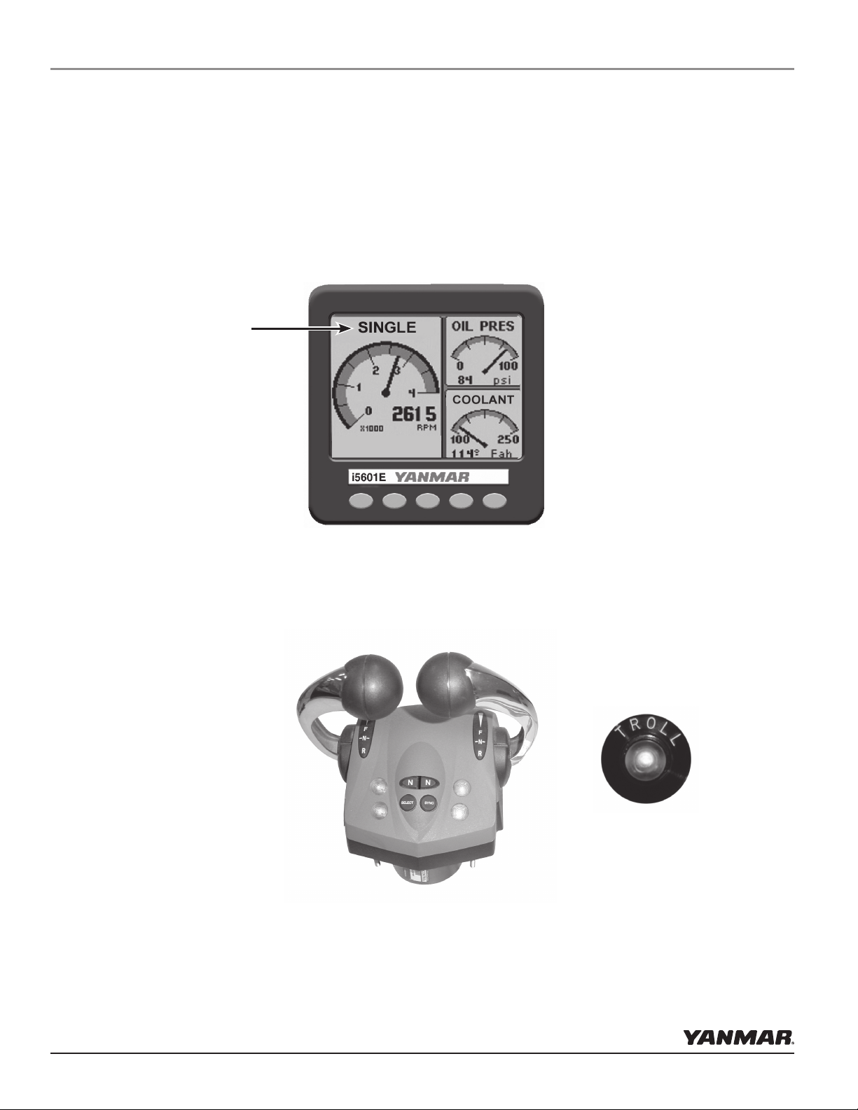
Helm Components .......................................................................................................................................2
Start Up ..............................................................................................................................................................3
Redundant (Back Up) Throttle .....................................................................................................................3
i5601E ..........................................................................................................................................................4
First Time Control Operation ......................................................................................................................6
Shift and Throttle Control Head Operation..................................................................................................6
Operation ............................................................................................................................................................7
Control Head Operation ..............................................................................................................................7
Identication ..........................................................................................................................................7
Select/Change Station ............................................................................................................................7
Indicator Dimming Feature ....................................................................................................................7
Shift Disconnect (SD) ............................................................................................................................8
Split Range Throttle (SRT) ....................................................................................................................8
Sync Operations .....................................................................................................................................9
Cruise Sync (CS)..............................................................................................................................9
Power Train Sync (PTS) ..................................................................................................................9
Trolling Mode (option) ..............................................................................................................................10
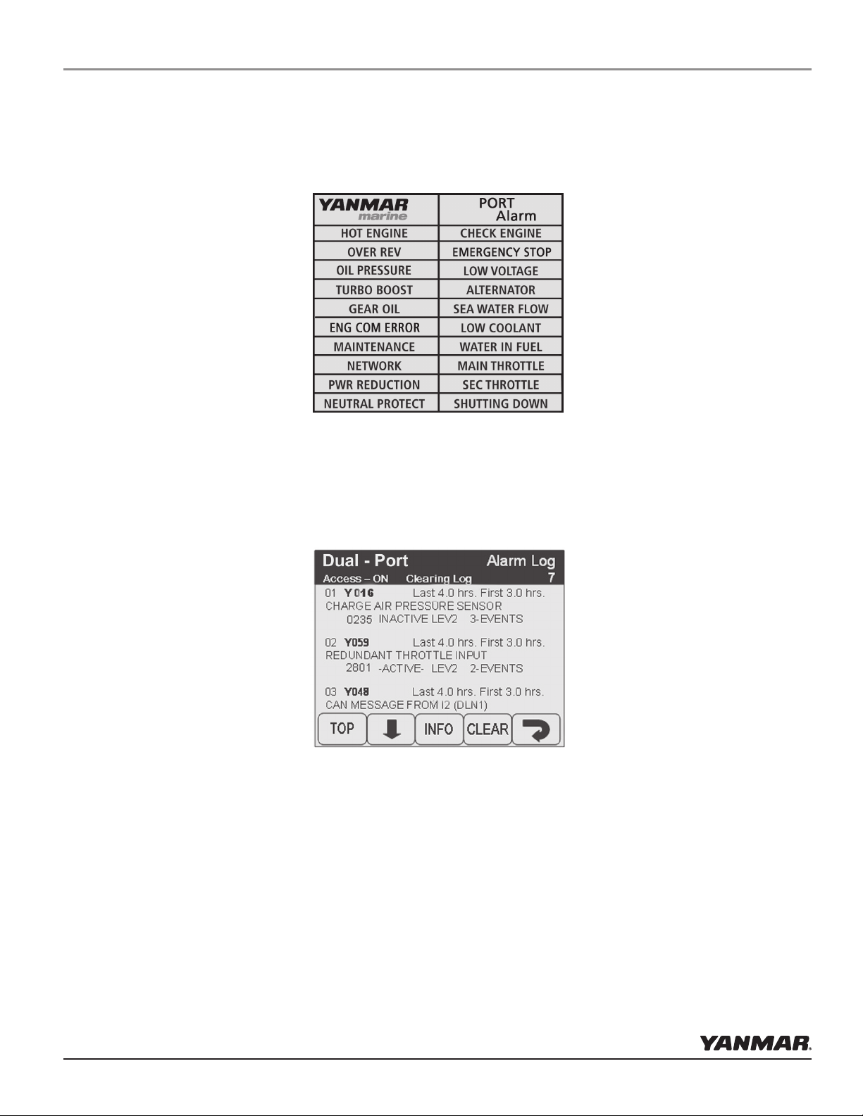
i5601E Digital Display Alarms/Diagnostic Code Screens ........................................................................11
Engine Alarms ......................................................................................................................................12
Engine Diagnostic Codes .....................................................................................................................12
Maintenance Warning ..........................................................................................................................12
Power Reduction Mode ..............................................................................................................................12
Diagnostics .................................................................................................................................................13
System Alarms ...........................................................................................................................................13
i8350/55 Operation ..........................................................................................................................................14
Appendix A: i5601E Digital Display Setup .....................................................................................................15
Display Settings .........................................................................................................................................16
Menus .........................................................................................................................................................16
User Settings and Factory Settings ............................................................................................................17
“Unlocking” the Hot Keys .........................................................................................................................17
Quad Screen Parameters ............................................................................................................................18
Appendix B: i5601E Menu Navigation ..........................................................................................................19
Appendix C: Default Settings .........................................................................................................................20
Appendix D: Fuses ...........................................................................................................................................21
Appendix E: Trouble Codes .............................................................................................................................21
Appendix F: Station Select Protection .............................................................................................................23
Appendix G: Network Status ...........................................................................................................................24

Page 2 © Yanmar 2008
Electronic Control System:
Operation Manual for SY Series Engines with GEN III Controls
System Overview
This dual engine electronic control system consists of the following helm equipment:
•Two Yanmar i5601E Digital Displays (one, if single engine)
•Dual Shift & Throttle Control Head (single shift & throttle control head, if single engine)
Yanmar i5601E Digital Display
The i5601E displays real-time data as well as warnings or alarms for any engine abnormality. Diagnostic codes
will be stored for future reference by a Yanmar technician.
Shift & Throttle Control Head
The Shift & Throttle Control Head selects the gear positions and the throttle settings. The Control Head has
several lights that conrm modes of operation and display warnings, if present. Buttons enable engine RPM
synchronization and shift disconnect as well as setting the brightness of the lights.
Other control congurations with the same functions but different form factors may be used. Refer to the
supplemental material included with those controls.
Helm Components
Although the scope of this document relates to both single and dual engines, the instructions within depict
the more widely used dual engine conguration.
Note: Displays “Single”
if single engine
conguration.
CP67601: Trolling Switch
(Optional)

© Yanmar 2008 Page 3
Electronic Control System:
Operation Manual for SY Series Engines with GEN III Controls
Start Up
WARNING
In normal operating mode, the engine is started and stopped with either the key switch, or the OFF-
ON-START rocker switch.
In an emergency situation, you can use the Emergency Stop switch to kill all power to the engine. This
will allow you to stop at once.
Place the control levers in neutral and turn the PORT ignition switch to the On position – but do not start the
engine. The green control head light will illuminate.
Check to see if the green light on the control head is solid or ashing. If solid, proceed to the next step. If
ashing, push the Select button to select the head. Position the control lever to neutral and the yellow light will
now come on.
Redundant (Back-up) Throttle
In the unlikely event that the throttle signal is lost between the helm mounted shift/throttle control head and the
engine, the system is designed to revert to the redundant or back-up throttle. First, the engine would reduce rpms
to idle speed, the digital display would show “Throttle Error,” and a small red indicator light would ash at the
key panel (or switch panel). Near the red light is a small potentiometer (looks like a volume control knob). Turn
the knob ALL the way to counter-clockwise in order to take control of the throttle. Then turn the knob SLOWLY
to clockwise - the light will glow solid. You will have control of the throttle, however, you will NOT have shift
control. When the signal loss problem has been corrected, you must shut the engine off and restart to return
throttle control back to the shift/throttle control head.
For Emergency Shift see transmission manual.
WARNING
Completely review the start-up procedures on pages 3 through 6 before starting the engine.
Two-position Emergency Stop Switch
(must be in “off” position to run engine -
bottom pushed in)
Three-position
Off-On-Start Switch
Potentiometer
"Subthrottle"
Red Indicator
Light

Page 4 © Yanmar 2008
Electronic Control System:
Operation Manual for SY Series Engines with GEN III Controls
In the unlikely event that an engine fault occurs, a warning box appears in the
display showing the cause of the fault, and the action to take, "Press Any Key
To Continue."
These screens show all of the key engine data and can be accessed by pushing a single button. The right-most
button allows the contrast and brightness to be set (see illustration below).
Start Up
i5601E Digital Display
When powered-up, the i5601E Digital Display will initially display an introductory screen showing the software
revision level. It will then display one of the following four screens:

© Yanmar 2008 Page 5
Electronic Control System:
Operation Manual for SY Series Engines with GEN III Controls
Pressing any key acknowledges the alarm and immediately switches the display to the Alarms screen. The
i5601E continues to beep until all alarm conditions (engine faults) have cleared. Unacknowledged alarms are
shown as ashing boxes. Press any key to acknowledge alarm boxes that may still be ashing, and they will then
change to a steady highlighted state.
Start Up
Engine Diagnostic Code Summary Screen
The i5601E is an extremely versatile display. The four-left keys can be recongured to allow the user to display
whatever screens he or she desires. For additional operational details, refer to the Appendix A.
Alarm blocks remain highlighted as long as the alarm condition (engine fault) remains and will automatically
reset to an un-highlighted state after the alarm condition has passed.

Page 6 © Yanmar 2008
Electronic Control System:
Operation Manual for SY Series Engines with GEN III Controls
Various features of the electronic control system have been selected and set as part of the installation. They can
be checked in Appendix C. They include:
• Max Throttle Amount in Split Range Throttle (SRT)
• Shift Delays
• Type of Sync (Power Train or Cruise)
•Station Protection
1. Before starting the engines for the rst time, take a moment to familiarize yourself with the shift and throttle
controls. With the engines not running, move the control levers over the full range until you are familiar with
the feel. Note that the detent pressure and drag can be adjusted using the adjusting screw on the front surface
of the control head. The top screw sets the detent pressure; the lower screw sets the drag.
2. Place the control levers in neutral and turn the ignition switches to the ON position -- but do not start the
engine. The green control head light will illuminate.
a. Check to see if the green light on the control head is solid or ashing. If solid, proceed to the next step.
If ashing, push the Select button to select the head. Position the control lever to neutral and the yellow
light will now come on.
The Shift & Throttle Control Head selects the gear positions and the throttle settings. The Control Head has
several lights that conrm modes of operation and display warnings, if present. Buttons enable engine RPM
synchronization and shift disconnect as well as setting the brightness of the lights.
Other control congurations with the same functions but different form factors may be used. Refer to the
supplemental material included with those controls.
Shift & Throttle Control Head Functions
The most common Shift and Throttle Control Head comes with a dual function, single lever control. A single
lever control initiates both shifting and throttle for a single engine.
First Time Control Operation
Start Up
Note that the detent pressure and drag can be adjusted using the
adjusting screw on the front surface of some control heads.

© Yanmar 2008 Page 7
Electronic Control System:
Operation Manual for SY Series Engines with GEN III Controls
Operation
Control Head Operation
The boat will start to move during the next steps. Be very cautious when rst
engaging the gears to establish that forward is truly forward and reverse is
truly reverse. A quick in-and-out of gear test is recommended. Ensure that
the boat is clear of all obstacles forward and aft before conducting this test.
WARNING
Select/change Station:
NOTE: Station Protection may be turned on, see Appendix F.
A lit green SELECT lamp indicates a station is active.
• On single station boats, station selection is automatic.
• For multi-station boats, choose a station and then press
SELECT button with levers in neutral.
to Change Stations:
• Move to new station and press select button. (Green lamp
ashes.)
• Match control handle positions with those of active station.
(Green lamp goes steady when levers match and this station
is now in control.)
Engine Trim Control:
in the handle (optional)
Lever Position Indicators:
Shift
Detent
Throttle
Friction
ADJUSTABLE LEVER FEEL
Starboard Port
Identication
Indicator Dimming Feature:
Push SELECT button and the lamps will dim. There are four
degrees of brightness from which to choose.
NOTE: Indicator Dimming is only accessible from the active
control station. (Green lamp on steady.)

Page 8 © Yanmar 2008
Electronic Control System:
Operation Manual for SY Series Engines with GEN III Controls
Shift Disconnect (SD):
Flashing yellow N (Neutral) lamp indicates SD engaged for this
engine. Allows throttle control without gear engagement.
TO ENGAGE Shift Disconnect:
• Move engine’s lever to the “Neutral” position.
• Press the N (Neutral) button next to this lever. (Yellow lamp
ashes.)
To Disengage Shift Disconnect:
• Return engine’s lever to the “Neutral” position.
• Press N (Neutral) button next to this lever. The yellow
N (Neutral) lamp will go steady - SD is disengaged and
the engine and transmission will now respond to lever
commands.
NOTE: The ashing yellow N (Neutral) lamp can indicate status of either Shift Disconnect (SD) or Split
Range Throttle (SRT). Please exercise caution when engaging/disengaging either of these modes! A steady-on
Neutral lamp ALWAYS indicates engine is in NEUTRAL.
Split Range Throttle (SRT):
Flashing yellow N (Neutral) lamp - SRT engaged for this
engine. Provides greater throttle sensitivity: moving an
engine’s control lever to “Full Forward” will only produce the
maximum percentage of WOT (Wide Open Throttle selected
at set-up - default Throttle Limit is 25%)
TO ENGAGE Split Range Throttle:
• Move engine’s lever to Forward Idle position.
• Press N (Neutral) button next to this lever. (Yellow lamp
ashes.)
TO DISENGAGE Split Range Throttle:
• Move engine’s lever to Forward Idle or Reverse Idle
• Press N (Neutral) button next to engine lever. The yellow N
(Neutral) lamp will go out - SRT is disengaged.
Operation

© Yanmar 2008 Page 9
Electronic Control System:
Operation Manual for SY Series Engines with GEN III Controls
Power Train Sync (PTS):
Automatically synchronizes engines and transmissions; the port
lever controls throttle and shift of both engines across the entire
control range.
A lit red SYNC lamp indicates sync is engaged.
TO ENGAGE PTS:
• Press SYNC button. (Red lamp ashes.)
• Match control handle positions within 5% of each other.
(Red lamp goes steady when levers match — power trains
are now in sync.)
TO DISENGAGE PTS:
• Press SYNC button. (Red lamp ashes.)
• Match control handle positions within 5% of each other.
(Red lamp goes off when levers match — power train sync
is now disengaged.)
Sync Operations:
NOTE: Your system ships with Cruise Sync set as the default.
Power Train Sync may be selected using the i5601E display.
Cruise Sync (CS): Default
Automatically synchronizes engine RPMs when levers are
close together and above 20% forward throttle.
A lit red SYNC lamp indicates sync is enabled.
TO ENABLE CS:
• Press SYNC button. (Red lamp ashes.)
• Match control handle positions within 5% of each other.
(Red lamp goes steady when levers match — CS is now
enabled.)
CS AUTOMATIC ENGAGEMENT:
• When levers are moved within 10% of each other and over
20% forward throttle.
CS AUTOMATIC DISENGAGEMENT:
• When levers are moved more than 10% apart or under 20%
forward throttle.
TO DISABLE CS:
• Press SYNC button. (Red lamp ashes.)
• Match control handle positions within 5% of each other.
(Red lamp goes off when levers match — cruise sync is
now off.)
Operation
Note: Starboard lever may be
chosen as master control using
the i5601E

Page 10 © Yanmar 2008
Electronic Control System:
Operation Manual for SY Series Engines with GEN III Controls
Optional Trolling Mode
The Trolling mode option allows the boat operator to slow the forward and aft speed of the boat for shing.
Trolling mode is achieved by the ECU electronically adjusting pressure bypass valves in the gearbox, allowing
the clutches to slip.
When trolling is selected (by pressing the separate trolling switch) and the control lever is moved forward, the
boat will start to move at the slowest speed. The factory default conguration for trolling operation is the Split
Trolling mode. This operation allows the operator to perform from minimum prop RPM (full slip) to maximum
prop RPM (full lock up) and then a throttle ramp up with one lever motion. The defaults are: 60% of the lever
movement from gear-idle to maximum prop RPM, with the remaining 40% lever movement used for throttle
control to a maximum of 40% throttle.
The trolling defaults -- as shown in Appendix C -- can be set to a variety of operating modes. Contact your
dealer for details, or see technical manual.
How to Enter Trolling Mode:
1) Move the Control Head lever(s) to the Neutral position.
2) Start the engine(s) if necessary. The system must see RPM in order to permit trolling mode to be entered.
3) Press the separate trolling switch. This places the system in trolling mode. The trolling light will illuminate
to indicate trolling mode is active.
4) When you move the Control Head lever(s) in either the forward or reverse direction, the engine RPM will
remain steady, but the boat should move in the selected direction.
5) To take the boat out of the trolling mode, return the Control Head lever(s) to the Neutral position and press
the Trolling switch.
Operation
Control Lever Range of Operation
Note: Split Range Throttle (SRT) is not operational while engaged in Trolling mode.
........................................................
60%
40%
TrollingThrottle
40% Throttle
Full Lock-up
CP67601 Trolling Switch
Trolling Switch

© Yanmar 2008 Page 11
Electronic Control System:
Operation Manual for SY Series Engines with GEN III Controls
Operation
i5601E Digital Display Alarms/Engine Diagnostic Codes
Engine Alarms/Diagnostic Codes
The ALARMs / DIAGs Screen Menu allows user to go the Alarm or Diag Code Screen. This is very useful in
the HOT KEY Mode, as a dedicated hot key is not required to view these screens. User can hold Right most
key down go into the menu mode and then via this menu access the desired screen.
Performs the function indicated by a pop-up menu,
if present.
With no pop-up menu showing, briey press to
display the Lighting & Contrast menu.
With no pop-up menu showing, press and HOLD
to display the MAIN MENU.
Buttons
“Down” Arrow moves menu selection down
“Up” Arrow moves menu selection up
“Right” Arrow acts on current menu item
“Back” Moves back to previous menu

Page 12 © Yanmar 2008
Electronic Control System:
Operation Manual for SY Series Engines with GEN III Controls
Operation
Engine Alarms
The Alarm Screen will display the status of 20 dened alarms.
A ashing black background indicates unacknowledged alarm; a
solid black background indicates an acknowledged still in alarm
state status.
Engine Diagnostic Codes
This screen displays the diagnostic code information. The title bar
indicates the number of diagnostic items.
Maintenance Warning
The maintenance timer will activate at between the rst 50 to 60 hours of operation. A maintenance warning
will be displayed on the digital display screen. To acknowledge this warning, press and hold the #5 (right most)
button on the i5601E digital display for a few seconds until the main menu is displayed. Use the down arrow
button to move the courser to “User Settings.” Press the right arrow button to enter the “User Setting” menu.
The arrow should be at the “Reset Maint. Time” selection. Press the right arrow key to reset. The warning will
go away. When 250 hours of operation after the reset has occurred, the maintenance warning will be displayed
again. This will occur every 250 hours thereafter. This a reminder that periodic maintenance must be performed
at these intervals.
Power Reduction Mode
An automatic protection mode called Power Reduction is included in the electronic control system to help
protect the engine from major failure. The Power Reduction mode will be activated if the oil pressure drops
below 2.3 bar (33 psi) for more than 5 seconds at an engine speed above 1000 RPM. In this mode the maximum
power will be reduced to 70% of normal.
On multi-engine boats the following actions occur on Power Reduction.
Condition Engine with Power Reduction Action
Sync OFF Either Engines operate independently
Sync ON Master Slave slowly matches master
Sync ON Slave Master normal, slave slows

© Yanmar 2008 Page 13
Electronic Control System:
Operation Manual for SY Series Engines with GEN III Controls
Diagnostics
The i5601E digital display indicates if certain malfunctions occur. The system
also stores certain DTC (Diagnostic Trouble Codes) for reference. These codes
will help you or a technician to determine which subsystem has malfunctioned.
Display and record all Trouble Codes so you can relay them to the technician.
A listing of possible Diagnostic Trouble Codes are in Appendix E.
There are also diagnostic lights built into the Electronic Control System to
assist in troubleshooting. The shift/throttle control head will ash to indicate
improper operation (see the section on the control head function).
There is an i8350 or i8355 Engine Control Unit (ECU) mounted in the engine
room. On the ECU module are three LED indicator lights which normally
ash to acknowledge proper operation. When the ignition switch is “ON”
and/or the engine is running, the three LED indicators will ash at various
rates to indicate the following:
Operation
• ENGINE CONTROL UNIT STATUS BLUE
• J1939 CANBus OPERATION YELLOW
•NMEA2000® CANBus OPERATION GREEN
If any of these are not ashing, consult your dealer.
i8350/55
Engine Control Unit
Critical Alarms
Continuous ashing both lights on either side of the
control indicates a Critical Alarm. System will do a “Safe
Shut Down,” and must be serviced before further use.
When a critical alarm occurs, the system will automatically
go to the selected “Fail Safe Response” mode. The system
MUST be shut down and restarted for most critical alarms.
Some functions may operate for a time after restart. See
display on Control Unit to determine cause of alarm.
If the alarm is caused by the Throttle Actuator hitting
“Stop” - Wide Open Throttle (WOT) - the alarm will go
away when the throttle is pulled back. However, as with
ALL Critical Alarms, the system must be serviced before
further use.
Non-Critical Alarms
Intermittent ashing of both lights on either side the
control (ve seconds ash, normal for fteen seconds, then
repeating), indicates a Non-Critical Alarm. Acknowledge
by a power up cycle. Continue to operate and have the
system checked as soon as possible.
System Alarms

Page 14 © Yanmar 2008
Electronic Control System:
Operation Manual for SY Series Engines with GEN III Controls
i8350/55 Operation
i8350/55 Engine Interface Module
The switches inside the i8350/55 allow for starting and stopping the engine.
• Turn on the ignition switch at the helm.
• To start the engine, turn on Emergency Start Power by pressing
in the top of the Emergency Start Power Switch. The buzzer
will sound.
• Start the engine by pressing in the top of the Emergency
Engine Start Switch.
• Stop the engine by pressing the RED “Stop” button.
For indicator light information, see page 13.
Programming connector.
Factory use only.
Important Note:
No service items
exist behind this
panel.
Removal of this
panel will void
the warranty

© Yanmar 2008 Page 15
Electronic Control System:
Operation Manual for SY Series Engines with GEN III Controls
Appendix A
The i5601E was set up at the factory with the keys assigned and locked as shown on page 4 of this manual. This
mode is the default mode and allows start up and operation of the engine. It serves many applications quite well.
The i5601E Digital Display unit has many additional features and capabilities. This section of the book shows
the use of some of these features.
Changing the basic set up is typically accomplished in one of two ways.
1. Go to the systems menu and alter basic selections
2. Enable the right arrow key (5) on the basic screens to allow changing of the data shown in the default
displays.
To enter the Main Menu press and hold key 5 until the menu appears.
To move around the menus use the softkeys at the bottom of the screen.
The function of a particular softkey changes from screen to screen to
whatever is most appropriate for the given screen.
Keys 1 2 3 4 5
i5601E Digital Display Setup
NOTE: Any changes to the setup menus may require reconguring the i5601E HOT KEY SETUP.

Page 16 © Yanmar 2008
Electronic Control System:
Operation Manual for SY Series Engines with GEN III Controls
Appendix A
Display Settings
The Monitor Settings Menu allows setting of parameters that are specic to the display unit. Some settings such
as Language and Lighting will be communicated to the other displays.
Display Description Function
MENU HOT KEYS LOCK Controls the actions of the keys
UNITS Sets a variety of units to suit the operator
LANGUAGE Sets the language the unit will display
TACH RNG 0-3000 Sets the tach range
SPEED Allows adjustments to speed readings if available
DEPTH OFFSET Allows adjustments to depth readings if available
DEFAULT MONITOR Returns the unit to the default settings
BEEPER ON Turns the key beeper on and off
ABOUT Supplies information about the display
Menus
This menu controls the key functions. There are three choices:
1. When the Pop-Up Menus feature is selected (drawing at right), the unit
functions like a typical computer. A key push brings up a menu and you
then use the keys to make a series of selections. This is the mode that
allows new screen set ups to be selected and any screen to be accessed.
2. The Hot Key Locked selection allows keys 1, 2, 3, and 4 to be assigned as
favorite screens. Pushing the key immediately brings up the selected screen.
This mode will not display the right arrow over key 5. Thus the screens are
locked when this is selected. This is the factory default setting.
3 . The Hot Key selection allows keys 1, 2, 3, and 4 to be assigned as favorite
screens. Pushing the key immediately brings up the selected screen. This
mode will display the right arrow above key 5. That arrow allows the user
to select various data inputs in the various sections of the screen.

© Yanmar 2008 Page 17
Electronic Control System:
Operation Manual for SY Series Engines with GEN III Controls
Appendix A
User Settings and Factory Settings
• The user setting allows for reset of the maintenance timer.
• The factory settings require a password to change.
“Unlocking” the Hot Keys
This is a popular way to expand the use of the i5601E. To unlock the hot keys and allow for additional data
selections go to the Main menu, as described on page 16. Then select HOT KEYS. Exit the menu back to the
normal operating screens. You will see a right hand arrow above key 5 when any key is pressed.
The Right Arrow button changes the menu to allow selection of each block. Pressing a block key will cycle
through the choices listed on the next page. The choices are presented in alphabetical order. Bold items are the
default settings and will appear initially unless replaced by an indented item listed underneath.
Note: Data in NMEA 2000® format may be added to the CANBus system from a compatible device which
feeds the optional parameters listed above. The i5601E display has the capability of displaying additional
information as other devices with NMEA 2000® communication capabilities are added to the vessel.
Example using a quad screen:
1 2 3 4 5
Hot Keys
1 2 3 4 5
Block Keys
Each button cycles the related block
through the list on the next page.

Page 18 © Yanmar 2008
Electronic Control System:
Operation Manual for SY Series Engines with GEN III Controls
Appendix A
Quad Screen Parameters
These data choices can be placed in any box of a quad screen or in the two small boxes of an engine data screen.
The screen headings that are included in a standard set-up are noted in bold.
Screen Heading Function Typical Data Source
Battery Battery Voltage Engine
Bearing Bearing to Waypoint GPS
COG Course Over Ground GPS
Coolant Engine Coolant Temperature Engine
Depth Depth of the water Sonar
Fuel Fuel level if single engine Sender
Fuel Center Fuel Level in the center tank Sender
Fuel Port Fuel Level in the port tank Sender
Fuel Rate Instantaneous fuel burn rate per engine Engine
Fuel Starboard Fuel Level in the starboard tank Sender
Gear Indicates the selected gear Engine
Heading Current vessel heading Compass
Hours Actual Engine Hours Engine
Load Percent load on engine Engine
Network Network voltage Engine
Oil Pressure Engine Oil Pressure Engine
Oil Temperature Engine Oil Temperature Engine
RPM Engine Revolutions Per Minute Engine
Rudder Rudder Angle Sender
Sea Temp Sea Water Temperature Sender
SOG Speed Over Ground GPS
Speed (SOW) Speed through the water Sender
Tab Port Position of the Port Trim Tab Sender
Tab Stbd Position of the Starboard Trim Tab Sender
Throttle The percent of throttle currently selected Engine
Torque The percent torque the engine is developing Engine
Turbo The amount of turbo boost pressure Engine
Waste The amount of waste in the holding tank Sender
Water The amount of water in the water tank Sender
WP Dist The distance to the selected waypoint GPS
XTE The cross track error from a best source GPS
Note: Data in NMEA 2000® format may be added to the CANBus system from a compatible device which
feeds the optional parameters listed above. The i5601E display has the capability of displaying additional
information as other devices with NMEA 2000® communication capabilities are added to the vessel.
This manual suits for next models
1
Table of contents
Popular Control System manuals by other brands

ENTRYPASS
ENTRYPASS EP.NE4800 Wiring guide

Festo
Festo ZSB-1/8-B Translation of the original instructions

Triangle MicroSystems
Triangle MicroSystems PETROSMART EZ installation instructions

Centralite
Centralite Elegance PC Programming Guide

Siemens
Siemens SINUMERIK 840D sl Function manual

Murphy
Murphy MGC2000 Installation and operation manual