YARD Commander YTL-590-043 User manual

to continually create quality products designed to enhance your home. Visit us online to see our full line of products available for your home
improvement needs. Thank you for choosing Yard Commander!
USE AND CARE GUIDE
10 CU. FT. STEEL DUMP CART
1-888-723-6534
Model # YTL-590-043
Questions, problems, missing parts? Before returning to the store,
please call Customer Service
8 a.m. - 5 p.m., PST, Monday - Friday
We appreciate the trust and condence you have placed in Yard Commander through the purchase of this 10-cu. ft. Steel Dump Cart. We strive

2
Table of Contents
Safety Information ..................................2
Warranty ..........................................3
Pre-Assembly 4
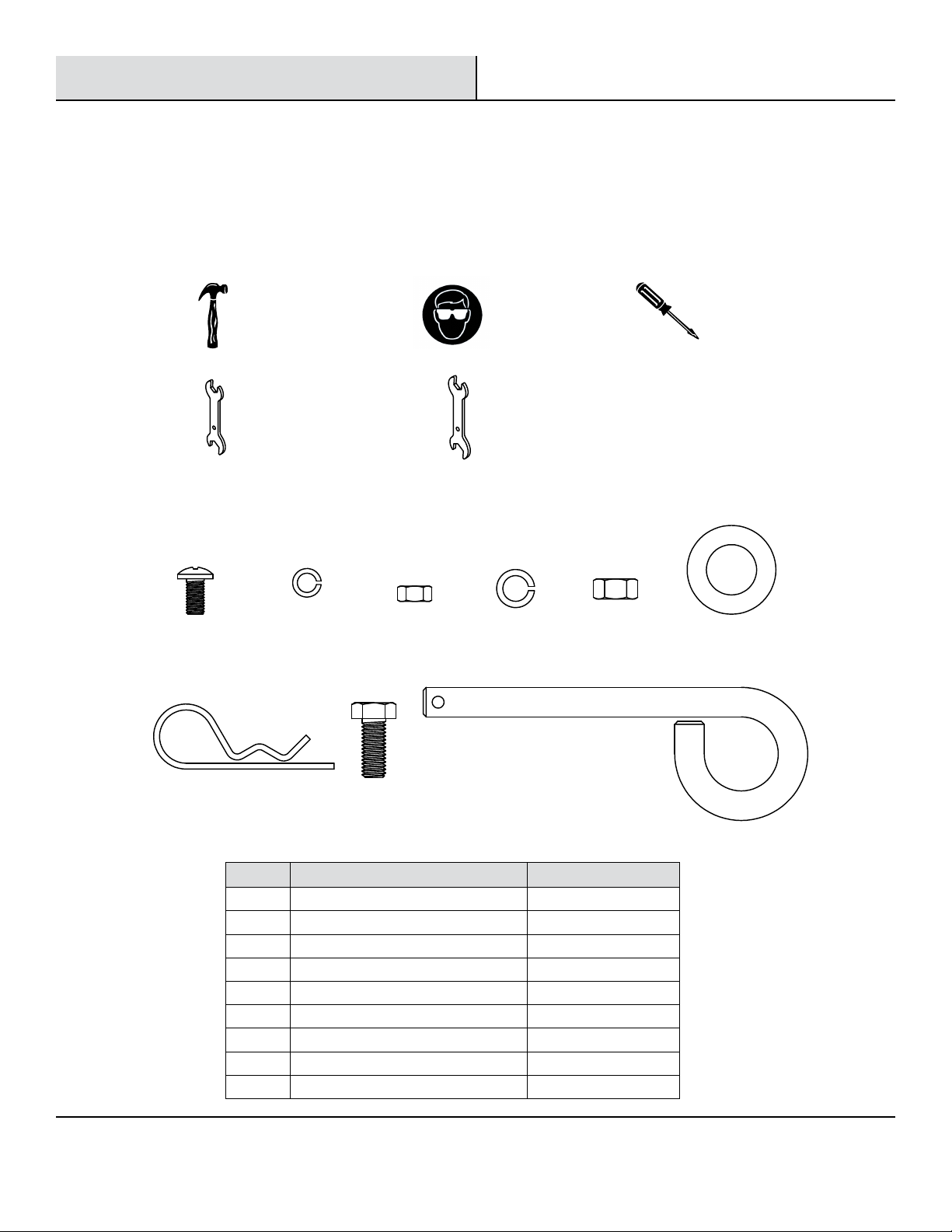
Tools Required ...................................4
Hardware Included ................................4
Package Contents .................................5
Assembly.................................... . . . 6-10
Operation .........................................11
Maintenance ......................................12
Care and Cleaning ..................................12
Service Parts ............................. . . . . . . 13-14
Safety Information
READ and UNDERSTAND this manual completely before using this Steel Dump Cart.
Operator must read and understand all safety and warning information, operating instructions, maintenance and storage instructions
before operating this equipment. Failure to properly operate and maintain the steel dump cart could result in serious injury to be
operator or bystanders.
Do not at any time allow passengers to sit or stand on the cart.
Do not allow children to play on, stand upon, or climb in the cart.
WARNING: This product can expose you to chemicals including lead and lead compounds which are known to the State of California to
cause cancer and birth defects or other reproductive harm. For more information, go to www.P65Warnings.ca.gov
Always inspect the cart before using to ensure it is in good working condition.
Replace or repair damaged or worn parts immediately.
Always check and tighten hardware and assembled parts before operation.
Do not exceed the equipment maximum load capacity of 400 Lbs.
Avoid large holes and ditches when transporting loads.
Be careful when operating on steep grades the cart may tip over.
Always operate at reduced speeds on rough terrain, along creeks, ditches and on hillsides.
Do not operate close to creeks, ditches and public highways.
To avoid personal injury and/or equipment damage DO NOT EXCEED 10 MPH.
Always use caution when loading and unloading the cart.
Only tow the cart with the recommended vehicles (Lawn/Garden Tractors and ATVs).
Always secure and lock dump cart to the vehicle hitch before operating.
.................................... ..
Always keep hands and feet clear from moving parts while operating the equipment.
Always clear and keep work area clean when operating.
Always wear safety gear, eye protection, gloves and work boots when operating the steel dump cart.
WARNING: The warnings, cautions, and instructions outlined in this instruction manual cannot cover all possible conditions or
situations that may occur. It must be understood by the operator that common sense and caution are factors which cannot be built into
this product and must be supplied by the operator.

3
Warranty
Warranty
For one year from the date of purchase, YTL International will replace for the original purchaser, or repair the steel dump cart. The
warranty will not apply to any unit which was not assembled correctly, misused, overloaded or which has been used oroperated contrary
to our instructions, or which has been repaired or altered by anyone other than an authorized representative.
Warranty Exclusions
This warranty does not cover cosmetic defects such as paint, decals or wear items such as tires. This warranty will not cover failures
or problems due to acts of God, or events or forces beyond the control of the manufacturer.
Normal Wear Exclusion
The steel dump cart needs periodic service to perform well. This warranty does not cover repair when normal use has exhausted the
life of a part or the equipment as a whole.
Installation, Use and Maintenance Exclusion
This warranty will not apply to parts and/or labor if the steel dump cart has been misused, neglected, involved in an accident, abused,
Limits of Implied Warranty and Consequential Damage Exclusion
YTL International disclaims any obligation to cover any loss of time, use of this product, freight, or any incidental or consequential
claim by anyone from using this steel dump cart. THIS WARRANTY IS IN LIEU OF ALL OTHER WARRANTIES, EXPRESS OR IMPLIED,
INCLUDING WARRANTIES OF MERCHANTABILITY OR FITNESS FOR A PARTICULAR.
An exchange unit will be subject to the original warranty. The length of the warranty governing the exchanged unit will have the date as
the purchase date of the original unit. This warranty gives you certain legal rights which may change from state to state. Your state may
also have other rights you may be entitled to that are not listed within this warranty.
Contact Information
YTL International Inc.
17517 Fabrica Way, Suite H
Cerritos, CA 90703
Phone: (888) 723-6534
Email: [email protected]

4
Please contact 1-888-723-6534 for further assistance.
Pre-Assembly
PLANNING ASSEMBLY
Before beginning assembly of product, make sure all parts are present. Compare parts with package contents list and hardware contents list.
If any part is missing or damaged, do not attempt to assemble the product.
TOOLS REQUIRED
10 mm Wrench 14 mm Wrench
HARDWARE INCLUDED
Part Description Quantity
AA M6x16 Screw 34
BB Ø6 Lock Washer 34
CC M6 Hex Nut 34
DD Ø8 Lock Washer 2
EE M8 Hex Nut 2
FF Ø16 Flat Washer 4
GG Ø3 R Pin 4
HH M8x30 Hex Bolt 2
II Hitch Pin 1
AA BB CC DD EE FF
GG HH II
Claw hammer Safety goggles Phillips
screwdriver

5
Pre-Assembly (continued)
PACKAGE CONTENTS
Part Description Quantity
A Bottom Panel Assembly 1
B Hitch Tongue Assembly 1
C Side Panel 2
D Rear Card Slot 2
E U-Frame 1
F Connecting Plate 1
G Rear Panel 1
H Wheel 2
A B C D
E GF HI
KJ LM
I Wheel Axle 1
J Hitch Pin Bracket 2
K Tongue Support 1
L Front Panel 1
M Corner Plate 2

6
Please contact 1-888-723-6534 for further assistance.
Assembly
1 Attach the Axle Support
and remove the two M6 wing nuts (X) on the wheel axle
supports. Fold the wheel axle supports in towards each
other. Then reinstall the M6 wing nuts (X) to the bottom
assembly (A).
2 Attach Tongue Support
CAUTION: Pay attention to the orientation of the hole during
assembly. The hole on tongue support (K) should be on the right
side.
Attach the tongue support (K) to the back of the bottom panel (A).
Pay attention to the orientation of the hole on the tongue support.
The hole should be oriented as shown below. Install four sets of
M6x16 screws (AA), Ø6 lock washers (BB) and M6 hex nuts (CC).
Hardware can be tightened later when cart is turned upright.
Hardware Used
x 2M6 Wing Nut
X
X
K
AA
BB
CC
Hardware Used
AA x 4M6x16 Screw
x 4Ø6 Lock WasherBB
x 4M6 Hex NutCC
X
X
A
A
Lay down the bottom panel assembly (A) on a at surface,

7
Assembly (continued)
3 Attach the Hitch Tongue Assembly
4 Attach the Wheels
put the wheel (H) on ensuring the male side of the wheel is
Ø16 at washer (FF) and lock in place using a Ø3 R pin (GG).
Repeat for the other wheel.
KB
AF
I
DETAIL A
FF
Hardware Used
x 4Ø16 Flat WasherFF
x 2Ø3 R PinGG
GG H
FF I
H
FF
FF GG
Add one Ø16 at washer (FF) on one side of the wheel axle (I),
facing the axle as shown below, and then put on another
Align the male receiver in the middle of the tongue assembly
(B) with the hole on the tongue support (K). Slightly pull the
release pedal (AF) back into the notch in the tongue support
to lock in place (see Detail A). Align the holes on the axle
supports (X) with the holes on the end of the tongue
assembly (B) and insert the wheel axle (I).

8
Assembly (continued)
5 Attach the Hitch Pin Bracket
Attach two hitch pin brackets (J) and the connecting plate
(F) to the hitch tongue (B) using two sets of M8x30 hex
bolts (HH), Ø8 lock washers (DD), and M8 hex nuts (EE).
Insert the hitch pin (II) through the bracket holes and
secure with the Ø3 R pin (GG).
6 Attach the Side Panel
Hardware Used
HH x 2
DD
EE
x 2Ø8 Lock Washer
x 2M8 Hex Nut
x 1Hitch Pin
x 1Ø3 R Pin
II
GG
M8x30 Hex Bolt
EE
DD
GG
HH
II
F
J
J
B
Turn the bottom panel over onto the wheels and tighten
hardware on the tongue support (K). Attach the side panel (C)
to the bottom panel (A) using three sets of M6x16 screws (AA),
Ø6 lock washers (BB), and M6 hex nuts (CC). Repeat on the
other side panel.
Hardware Used
AA x 6M6x16 Screw
x 6Ø6 Lock WasherBB
x 6M6 Hex NutCC
A
C
AA BB CC

9
Assembly (continued)
7 Attach the Front Panel
Attach the front panel (L) to the bottom panel (A) using
four sets of M6x16 screws (AA), Ø6 lock washers (BB),
and M6 hex nuts (CC).
Attach the front panel (L) to the side panels (C) using six
sets of M6x16 screws (AA), Ø6 lock washers (BB), and
M6 hex nuts (CC).
8 Attach the Corner Plate
Hardware Used
Attach the two corner plates (M) to the side panels (C) and front
panel (L) using four sets of M6x16 screws (AA), Ø6 lock washers
(BB), and M6 hex nuts (CC).
Hardware Used
AA x 4M6x16 Screw
x 4Ø6 Lock WasherBB
x 4M6 Hex NutCC
C
AA BB CC
AA x 10M6x16 Screw
x 10Ø6 Lock WasherBB
x 10M6 Hex NutCC
A
AA BB CC
L
L
CAA
BB
CC
M

10
Assembly (continued)
9Attach the U-frame
Attach the U-frame (E) to the bottom panel (A) and side
panels (C) using six sets of M6x16 screws (AA), Ø6 lock
washers (BB), and M6 hex nuts (CC).
Attach the two rear card slots (D) to the U-frame (E) and
both side panels (C) using four sets of M6x16 screws (AA),
Ø6 lock washers (BB), and M6 hex nuts (CC).
10 Attach the Rear Panel
Hardware Used
Slide the rear panel (G) through the rear card slots (D) on the
back side panels.
Hardware Used
GG x 1Ø3 R Pin
AA x 10M6x16 Screw
x 10Ø6 Lock WasherBB
x 10M6 Hex NutCC
G
A
E
D
C
AA BB CC AA BB CC
D
Insert the Ø3 R Pin (GG) into the safety pin on the hitch tongue.
Pull out the Ø3 R Pin (GG) before emptying the bed and then
press the release pedal.
GG
11 Lock the Tongue Support
AA BB CC

11
Please contact 1-888-723-6534 for further assistance.
Operation
WARNING: Before using the steel dump cart, review the instructions below and safety information.
Failure to follow these instructions may result in property damage or injury to the operator or bystanders.
DO NOT exceed rated capacity of 400 Lbs. (182 kg).
ALWAYS secure and lock the steel cart to the vehicle hitch before operating.
ONLY use approved vehicles when towing the dump cart (Lawn/Garden Tractors and ATVs).
NEVER tow the steel dump cart with box raised.
out of control.
ALWAYS use the dump cart for its intended purpose.
ALWAYS make sure that the tow vehicle and the combined weight of the operator MUST BE greater than the load of
the cart weight for proper control.
DO NOT use the cart on public highways or roads.
NEVER exceed 10 mph when towing the dump cart.
DO NOT make sharp turns that may cause the Lawn/Garden Tractor or ATV tires to rub against the steel dump cart.
ALWAYS slow down before turning.

12
Maintenance
After each use clean material out of the cart box.
Rinse/dry inside and outside of the dump cart after each use.
Before operating make sure the tires have the RECOMMENDED TIRE PRESSURE 30 PSI.
Care and Cleaning
Never allow material to remain in the steel dump cart for extended periods of time.
Before storing, make sure the cart is clean and dry for years of trouble-free service.
Store indoors or protected area during severe weather and winter months.
NOTE:
Regularly grease the axle and the wheel bearing area or when needed.
Periodically check all fasteners for tightness.
Annually clean and lightly lubricate parts.
Use a glossy enamel spray paint to touch up scratched or worn painted metal surfaces.
Never exceed load capacity rating of 400 Lbs. (182 kg). It will damage the steel dump cart.
WARNING: Improper maintenance and storage of the steel dump cart may void your warranty.
When storing outside always keep the tongue a little higher than the back of the cart to allow the moister to easily run out
the back and will not accumulate in the box.

13
Please contact 1-888-723-6534 for further assistance.
Service Parts
C
D
E
PON
G
N
O P X
NOP
C
Q R S
AD
AC
U
T
H
AA
IAB B
AE
AF AG
VRS
U
J
F
J
W
U
YZ
PON
K
L
M
A
NOPNOP
NOP

14
Service Parts (continued)
Part Description Quantity
A Bottom Panel 1
B Hitch Tongue 1
C Side Panel 2
D Rear Card Slot 2
E U-Frame 1
F Connecting Plate 1
G Rear Panel 1
H Wheel 2
I Wheel Axle 1
J Hitch Pin Bracket 2
K Tongue Support 1
L Front Panel 1
M Corner Plate 2
N M6x16 Screw 36
O Ø6 Lock Washer 36
P M6 Hex Nut 36
R Ø8 Lock Washer 8
S M8 Hex Nut 8
T Ø16 Flat Washer 4
U Ø3 R Pin 4
V M8x30 Hex Bolt 2
W Hitch Pin 1
X M6 Wing Nut 2
Y M6x90 Hex Bolt 1
Z M6 Hex Lock Nut 1
AA Axle Support 2
AB Axle Support Connecting Plate 2
AC Axle Support Hinge Pin 2
AD Ø2x25 Cotter Pin 4
AE Spacer 2
AF Release Pedal 1
AG Latch Spring 1
Q M8x16 Screw 6
Drawing No.
DC4002-00001
DC4002-01000
DC400-00002
DC400-00009
DC400A-20000
DC400A-00004
DC4002-00003
DC4002-02000
DC4002-00004
N390-00002
DC400-00007
DC4002-00002
DC400-00003
9199-06016-DX
9306-06000-DX
9201-06000-DX
9306-08000-DX
9201-08000-DX
9301-16000-DX
DC4002-00005-CD
9101-08030-DX
N180-00013
9208-06000-DX
9101-06090-DX
9206-06000-DX
DC0400-07000
DC0400-00001
DC0400-00002-DY
9404-02025-DX
N390-00005
N879-00002
N390-00003
9199-08016-DX

Retain this manual for future use.
1-888-723-6534
Questions, problems, missing parts? Before returning to the store,
please call Customer Service
8 a.m. - 5 p.m., PST, Monday - Friday
Other manuals for YTL-590-043
1
Table of contents
Other YARD Commander Outdoor Cart manuals