43
PLEASE READ - SAVE THESE
INSTRUCTIONS
When using an electrical gardening tools, basic safety pre-
cautions should always be followed to reduce the risk of
fire, electric shock, and personal injury, including the fol-
lowing.
WARNING
TO REDUCE THE RISK OF ELECTRIC
SHOCK, BURNS, FIRE OR PERSONAL
INJURY:
1. FOLLOW ALL SAFETY INSTRUCTIONS listed in
this manual before/during operation of this shredder.
2. GROUNDING INSTRUCTIONS this tool should be
grounded while in use to reduce the risk of electric
shock to the operator. The tool is equipped with a 3-
conductor cord and 3-prong grounding plug to fit the
proper grounding receptacle. The green or green and
yellow wire to live terminal. If your unit is for use on
less than 150 volts, it has a plug as illustrated in
sketch A in Figure 1 on page 2. If it is for use on 150
to 250 volts, it has a plug as illustrated in sketch D,
Fig.1, Page 2.
An adapter, sketches B and C, is available for
connecting plugs as illustrated in sketch A to 2-prong
receptacles. The green-colored rigid ear, lug, or the
like, must be connected to permanent ground, such
as a properly grounded outlet box. No adapter is
available for the plug illustrated in sketch D.
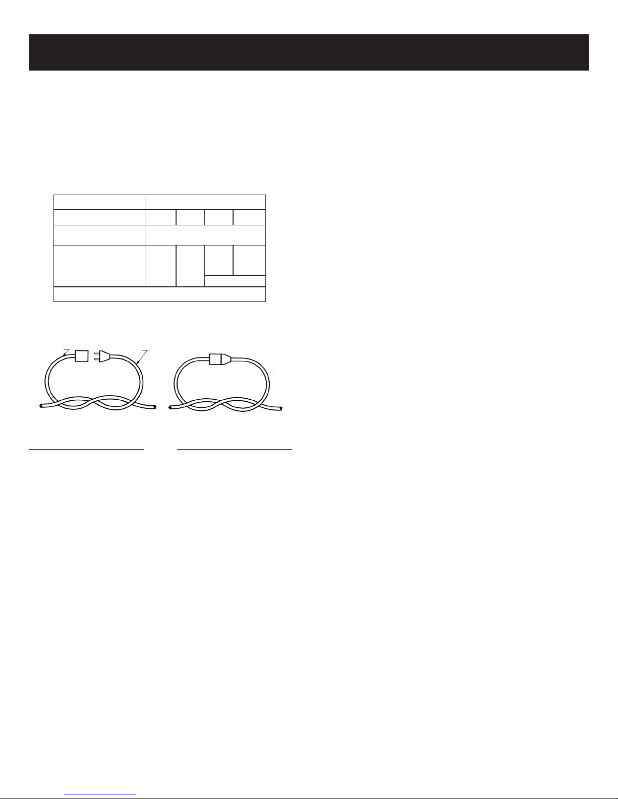
3. EXTENSION CORD - Use only with an extension
cord intended for outdoor use. Match wire gauge to
the cord length. See table below. A 2-wire cord with-
out a ground connection may be used since this
appliance is double insulated. If in doubt of proper
wire size, use the next heavier gauge. Please note
that the smaller the gauge number, the heavier the
cord.
4. AVOID DANGEROUS ENVIRONMENT - Do not use
appliance in damp or wet locations.
5. DON’T USE IN RAIN - Water entering a power tool
will increase the risk of electric shock.
6. DO NOT ABUSE CORD - Never yank it to discon-
nect from receptacle. Keep cord away from heat, oil,
sharp edges or moving parts. Replace damaged
cords immediately. Damaged cords increase the risk
of electric shock.
7. KEEP CHILDREN AWAY - All visitors should be kept
at a distance from work area.
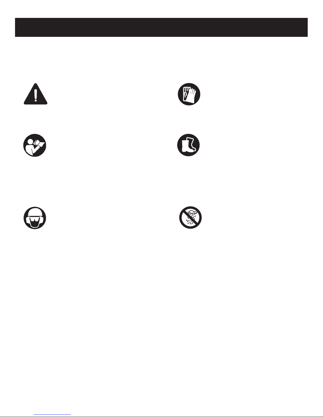
8. DRESS PROPERLY - Do not wear loose clothing or
jewelry. They can be caught in moving parts. Use of
rubber gloves and substantial footwear is recom-
mended when working outdoors. Wear protective hair
covering to contain long hair.
9. USE SAFETY GLASSES - Always use face or dust
mask if operation is dusty.
10. STAY ALERT, WATCH WHAT YOU ARE DOING AND
USE COMMON SENSE WHEN OPERATING A
POWER TOOL. Do not use tools while tired or under
the influence of drugs, alcohol, or medication. A
moment of inattention while operating power tools
may result in serious personal injury.
11. AVOID UNINTENTIONAL STARTING. Do not move
plugged-in appliance with finger on switch. Be sure
switch is off when plugging in.
12. DO NOT OVERREACH. Keep proper footing and bal-
ance at all times. Proper footing and balance enables
better control of the tool in unexpected conditions.
13. NO ACCESSORIES OR ATTACHMENTS ARE
NECESSARY FOR THE OPERATION OF THIS
GARDENING TOOL. The use of any accessories or
attachments for this gardening tool is not recom-
mended. Such use of any attachment or accessory
may increase the risk of injury to the user.
14. USE RIGHT APPLIANCE. Do not use appliance for
any job except that for which it is intended.
15. GROUND FAULT CIRCUIT INTERRUPTER(GFCI)
PROTECTION SHOULD BE PROVIDED ON THE
CIRCUIT(S) OR OUTLET(S) TO BE USED FOR
THE GARDENING APPLIANCE. Receptacles are
available having built-in GFCI protection and may be
used for this measure of safety.
16. WARNING! DTo reduce the risk of electric shock,
use only with an extension cord intended for out-
door use, such as an extension cord of cord type
SW-A, SOW-A, STW-A, STOW-A, SJW-A, SJOW-A,
SJTW-A, SJTOW-A.
Extension cords of the type specified above are
available at local hardware stores.Extension cord-
Make sure your extension cord is in good condition.
When using an extension cord, be sure to use one
heavy enough to carry the current your product will
draw. An undersized extension cord will cause a drop
in line voltage resulting in loss of power and overheat-
ing. Table 1 shows the correct size to use depending
on cord length and nameplate ampere rating. If in
doubt, use the next heavier gage. Number, the heav-
ier the cord. To reduce the risk of disconnection of
appliance cord from the extension cord during oper-
ating: Make a knot as shown in Fig. 2;
17. DO NOT FORCE TOOL. The correct tools will do the
job better and safer at the rate for which it is
designed.
18. DISCONNECT THE PLUG FROM THE POWER
SOURCE BEFORE MAKING ANY ADJUSTMENT,
CHANGING ACCESSORIES, OR STORING THE
TOOL. Such preventive safety measures reduce the
risk of starting the tool accidentally.
19. STORE IDLE TOOLS INDOORS. When not in use,
tools should be stored indoors in dry, and high or
locked-up place, out of reach of children.
20. MAINTAIN TOOLS WITH CARE. Keep cutting tools
sharp and clean for best performance and to reduce
the risk of injury. Follow instructions for lubricating
and changing accessories. Inspect tool cord periodi-
cally, and if damaged, have it repaired by an author-
ized service facility. Keep handling surface dry,
clean, and free from oil and grease.
21. CHECK DAMAGED PARTS. Before further use of
the tool, a guard or other part that is damaged
should be carefully checked to determine that it will
operate properly and perform its intended function.
check for alignment of moving parts, binding of
moving parts, breakage of parts, mounting, and any
other condition that may affect its operation. A
guard or other part that is damaged should be prop-
erly repaired or replaced by an authorized service
center unless indicated elsewhere in this manual.
SHREDDER SAFETY RULES:
1. Extreme caution should be taken to ensure shredda-
ble material does not contain metal. Rocks, bottles.
Cans or other foreign objects.
2. Do not allow hands or any other part of the body, or
clothing to enter inside the feeding chambers or dis-
charge chute, while machine is operating.
3. Wear gloves while operating the machine.
4. Before starting the machine, ensure that all screws
and other fasteners are properly secured.
5. Machine should be operated on firm level surfaces
only.
6. Before starting the machine, check that the cutting
chamber is empty.
7. Motor should be kept clean of debris and other
accumulations.
8. Keep all guards and deflections in good working
condition.
9. Stand clear of discharge chute at all times.
10.
Do not over reach and keep face and body back form
the feed opening.
11. Never pull the machine by the power cord and keep
cord away form water or sharp edges.
12. Disconnect the power cord when the machine is not
in use.
13. If machine should become clogged, switch off the
motor, disconnect the power cord, make sure all mov-
ing parts are completely stopped before cleaning
clogged debris.
14. Ensure the power cord is always in good condition. A
cord with broken insulation is extremely dangerous
and can result in fire, electric shock or serious per-
sonal injury.
15. The operation of any tools can result in foreign objects
being thrown into your eyes, which can result in
severe eye damage Before operating power tool,
always wear safety goggles or safety glasses with side
shields and a full face shield when needed. We rec-
ommend wide Vision Safety Mask for use over eye-
glasses or standard safety glasses with side shields.
RULES FOR SAFE OPERATION RULES FOR SAFE OPERATION
Fig. 1
GROUNDING
PIN
METAL SCREW
COVER OF
GROUNDED
DUTLET BOX
ADAPTER
GROUNDIN
G MEANS GROUNDIN
G PIN
Fig. 2
METHOD OF SECURING EXTENSION CORD
CORD SET APPLIANCE CORD
(A) TIE CORD AS SHOWN (B) CONNECT PLUG AND
RECEPTACLE
(A)
(C)
(B)
(D)
Volts
120V
Ampere Rating
More than Not more than
0-6
6-10
10-12
12-16
Total length of cord in feet
25 50 100 150
18
18
16
14
16
16
16
12
16
14
14
16
14
14
Not recommended
TABLE 1