Yard Works 060-3888-6 User manual

Ultimate Sawhorse
model no. 060-3888-6
IMPORTANT
Read this manual fully before assembly and use and
observe all safety rules and operating instructions
Toll-free: 1-866-523-5218
Instruction
Manual

2
model no. 060-3888-6 | contact us: 1-866-523-5218
Table of Contents
SPECIFICATION 2
EXPLODED VIEW 3
PARTS LIST 4
ASSEMBLY 5
OPERATION 10
SAFETY 13
WARRANTY 14
Specification
Minimum log diameter 5 cm 2”
Maximum log diameter 36 cm 14”
Maximum log length 6 m 19’ 8”
Maximum log weight 300 kg 661 lb
Length 1.32 m 51¾”
Width 50 cm 19 11/16”
Height 75 cm 29½”
Weight (including chain) 12.7 kg 28 lb

3
model no. 060-3888-6 | contact us: 1-866-523-5218
Exploded View
1 2 34 5
6
7
8
9
10
11
12
13
141516
16
17
18
19

4
model no. 060-3888-6 | contact us: 1-866-523-5218
Part List
Item Description Qty
1 Left upright 1
2 V-Blade 4
3 M12 nyloc nut 2
4 M12 x 125 mm socket button head bolt 2
5 Right upright 1
6 M6 x 20 mm socket button head bolt 2
7 M10 x 20 mm socket button head bolt 2
8 M6 nyloc nut 14
9 M8 nyloc nut 2
10 Locking pin 2
11 M6 x 40 mm socket button head bolt 12
12 M8 x 40 mm socket button head bolt 2
13 Back leg 2
14 Back foot 1
15 Front leg 2
16 Front foot 1
17 Brace 1
18 Log securing chain 1
19 M10 nyloc nut 2

5
model no. 060-3888-6 | contact us: 1-866-523-5218
Assembly
STEP 1:
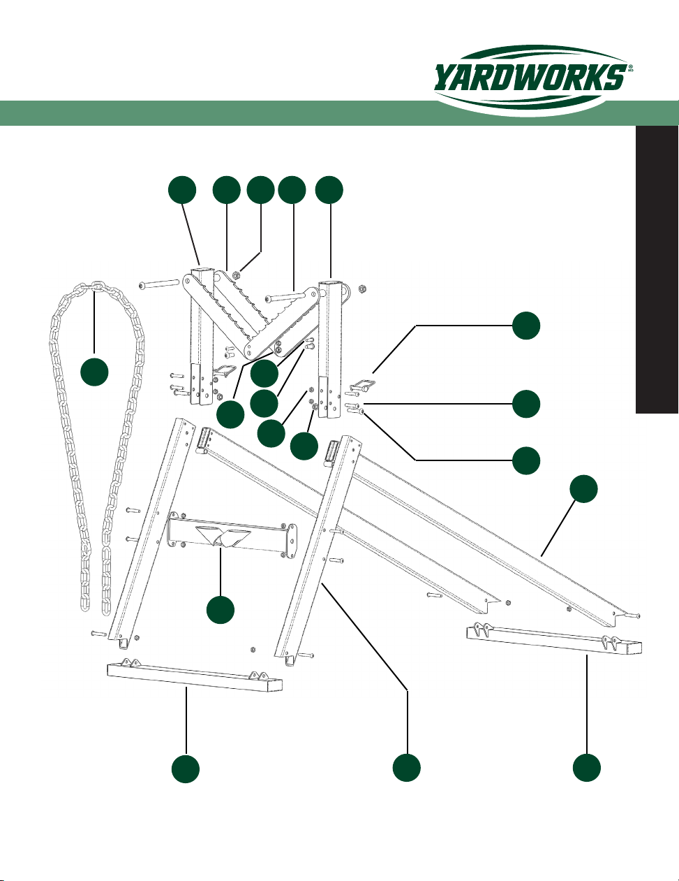
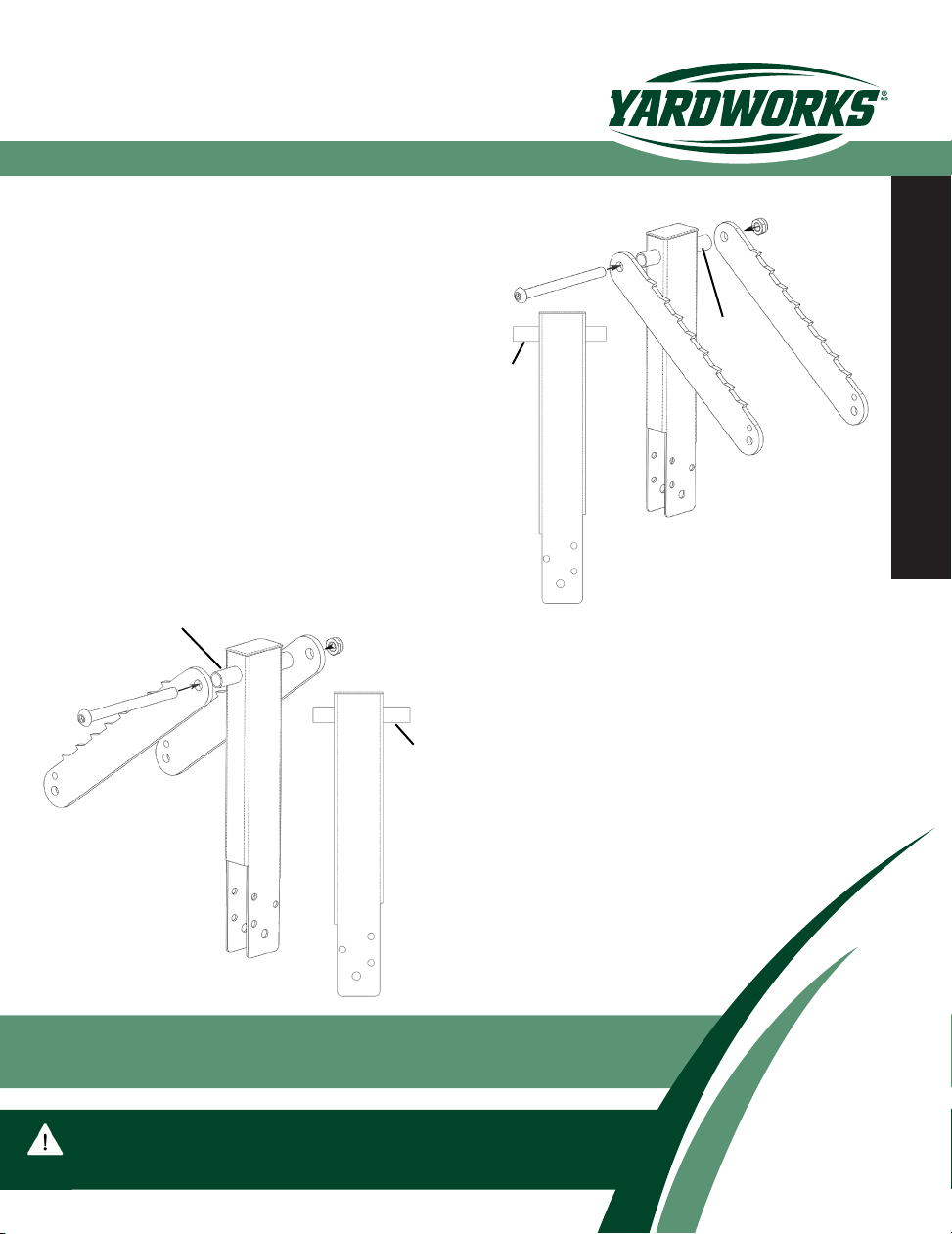
Connect the left upright (1) and 2
v-blades (2) using an M12 x 125 mm
bolt (4) and M12 nyloc nut (3). Note
that if the left upright is laid at, as
shown in the diagram then it has a
longer ferrule projecting to the left.
STEP 2:
Connect the right upright (5) and
the remaining 2 v-blades (2) using
the remaining M12 x 125 mm bolt
(4) and M12 nyloc nut (3). Note that
if laid at as shown, the right up-
right has the longer ferrule project-
ing to the right.
NOTE: Do not fully tighten nuts and bolts until after the
assembly is completed.
longer
longer
TOOLS REQUIRED: Spanners M6, M8, M10, M12
Allen keys 5 mm, 6 mm, 8 mm, 10 mm
longer
longer

6
model no. 060-3888-6 | contact us: 1-866-523-5218
Assembly
STEP 3:
Connect the v-blades of the 2
upright assemblies together using
2 M10 x 20 mm bolts (7) and 2
M10 nyloc nuts (20). Ensure that
the v-blades of the left and right
assemblies overlap as shown.
left
right
STEP 4:
Connect a front leg (15) to each of
the uprights using 2 M6 x 40 mm
bolts (11) and 2 M6 nyloc nuts (8).
The legs are inserted in the slot
in the bottom of the uprights and
the bolts passed through the 2
vertically aligned holes in each
upright and the corresponding
holes in the ends of each leg.
longer
longer

7
model no. 060-3888-6 | contact us: 1-866-523-5218
Assembly
STEP 5:
Connect the brace (17) between
the front legs using 4 M6 x 40
mm bolts (11) and 4 M6 nuts (8).
The brace should be oriented so
that the 2 chain tubes face away
from the v-blade assembly and the
horizontal openings in the tubes
face upwards.
STEP 6:
Connect the front foot (16) to the
front legs using 2 M6 x 40 mm
bolts (11) and 2 M6 nyloc nuts (8).
The front foot has the mounting
brackets on the top face of the foot.

8
model no. 060-3888-6 | contact us: 1-866-523-5218
Assembly
STEP 7:
Connect a back leg (13) to each upright using one M8 x 40 mm bolt (12) and one
M8 nyloc nut (9) per leg. The bolt should pass through the ferrule mounted at the
end of each leg, with the leg oriented so that the ferrule is on the underside.

9
model no. 060-3888-6 | contact us: 1-866-523-5218
Assembly
STEP 8:
Attach the back foot (14) to the
back legs using 2 M6 x 40 mm
bolts (12) and 2 M6 nyloc nuts (8).
STEP 9:
Complete the assembly by fully
tightening all nuts and bolts that
have been tted at each step.
IMPORTANT: Be careful not to lose the 2 M6 x 20 mm
bolts and M6 nuts and the 2 locking pins during
assembly, as these will be needed if loading heavy logs.
NOTE: Do not over tighten the M8 nut and bolt securing each
back leg to the uprights otherwise it will not be possible to
fold the sawhorse for storage.

10
model no. 060-3888-6 | contact us: 1-866-523-5218
Operation
STEP 1:
Open the legs of the sawhorse to
their maximum extent and place the
sawhorse on rm level ground so
that it is stable.
STEP 1A:
When cutting large heavy logs,
always insert the 2 locking pins (10)
through the uprights and the back
legs and add the 2 M6 x 20 bolts
(6) and M6 nyloc nuts (8) to the v-
blades.
10
6

11
model no. 060-3888-6 | contact us: 1-866-523-5218
Operation
STEP 3:
Place the chain over the log, in
line with the chain tubes and pass
the ends of the chain through the
tubes. Ensure that the ends of the
chain are approximately the same
distance from the ground.
STEP 4:
Push down on the raised end of
the log until it goes just past the
horizontal and check that both ends
of the chain slide through the chain
tubes.
STEP 2:
Raise the end of the log and
place it in the v-blades so that
approximately 1/3 of its length
overhangs the v-blades in the
direction of the brace.
1/3 log length

12
model no. 060-3888-6 | contact us: 1-866-523-5218
Operation
STEP 6:
Always begin by cutting the initial
few logs from the long overhang-
ing end, then cut successive logs
in a sequence that maintains ap-
proximately 1/3 of the remaining log
length in the direction of the chain
and 2/3 in the direction of the back
legs.
STEP 5:
Remove the downward pressure on
the end of the log so that the long
end moves downwards causing the
chain to lock in both chain tubes.
The log should be approximately
level. The angle of the log can be
adjusted by re-applying downward
pressure on the log and pulling or
pushing on the ends of the chain.
IMPORTANT: Check that the log is secure and the
sawhorse stable before beginning to cut.
IMPORTANT: The weight of the log is sufcient to securely
locate it in the v-blades, do not apply downward pressure to the
long overhanging end of the log as this may result in damage.
WARNING: If it is necessary to adjust the chain to change the angle of the
log, always hold the chain by the ends, never close to the chain tubes.

13
model no. 060-3888-6 | contact us: 1-866-523-5218
Safety
IMPORTANT SAFETY INFORMATION
Read and understand this manual fully before assembling and using the
sawhorse and observe all safety precautions. Non observance of safety
precautions may result in injury. Keep this manual for future reference.
Before using the sawhorse always check that all nuts and bolts are secure
and that the sawhorse is not damaged.
Use the sawhorse on rm level ground only. Do not use on sloping or
uneven ground.
After securing a log in the sawhorse, check the stability and balance before
starting to cut. The sawhorse must not be able to tilt.
Never hold the chain close to the chain tubes or place your ngers in the
chain links.
Read and observe the operating instructions of the chainsaw you are using
and wear all recommended safety gear. Always wear safety shoes or boots
in case a log is accidentally dropped on your feet.
Only cut with the bottom of the chainsaw bar as the log may otherwise shift
away from the rotating chain, become unstable and increase the risk of
personal injury.
Clear and stack the sawn logs away from the sawhorse to keep the
work area clear of obstructions and safety hazards.
WARNING: Do not exceed the specied maximum log
length and maximum log weight as given on page 2 of
this manual.

14
model no. 060-3888-6 | contact us: 1-866-523-5218
Warranty
Warranty
ThisYardWorks® product carries a one (1) year limited warranty against
defects in workmanship and materials. Should thisYardWorks® product
become defective within the stated warranty period, return it to the store
with proof of purchase, and it will be replaced or repaired free of charge.

14
modèle no060-3888-6 | communiquez avec nous : 1-866-523-5218
Garantie
Garantie
Cet article YardWorksMD comprend une garantie limitée de un (1) an
contre les défauts de fabrication et de matériau(x). S’il fait défaut au
cours de la période de garantie convenue, retournez-le au magasin,
accompagné de la preuve d’achat et il sera réparé ou remplacé sans
frais.

13
modèle no060-3888-6 | communiquez avec nous : 1-866-523-5218
Sécurité
CONSIGNES DE SÉCURITÉ
Assurez-vous de lire et de bien comprendre ce guide avant de tenter
d’assembler et d’utiliser le chevalet. Obéissez à toutes les consignes de
sécurité, sans quoi vous pourriez vous blesser. Gardez ce guide en lieu
sûr afin de pouvoir le consulter au besoin.
Avant d’utiliser le chevalet, assurez-vous que toutes les fixations sont
bien serrées et que le chevalet ne présente aucun dommage.
N’utilisez le chevalet que sur une surface ferme et de niveau. Éviter les
surfaces inégales et inclinées.
Une fois que vous avez installé une bûche sur le chevalet, vérifiez-en la
stabilité avant d’entreprendre la coupe. Assurez-vous que le chevalet ne
peut pas basculer.
Ne tenez jamais la chaîne près des tubes de chaîne, et ne mettez jamais
les doigts dans les maillons de la chaîne.
Assurez-vous de lire et de bien comprendre le mode d’emploi de la
scie à chaîne que vous utilisez, et portez tout équipement de sécurité
recommandé. Portez toujours des chaussures de sécurité pour protéger
vos pieds des bûches qui tombent.
N’effectuez les coupes qu’avec le bas du guide-chaîne de la scie à
chaîne, sans quoi la bûche pourrait bouger et devenir instable, ce qui
accroîtrait les risques de blessure corporelle.
Éloignez les bûches sciées du chevalet pour éviter d’encombrer la zone
de travail.
AVERTISSEMENT: Assurez-vous que les bûches que vous
voulez couper ne sont pas plus longues ni plus lourdes que ce
qui est préconisé à la page 2 du présent guide.

12
modèle no060-3888-6 | communiquez avec nous : 1-866-523-5218
Utilisation
ÉTAPE 6:
Commencez toujours par couper
le long bout en porte-à-faux de
la bûche. Par la suite, coupez les
rondins en alternant à chaque bout
de la bûche, de façon à garder
environ le tiers de la longueur du
côté de la chaîne et les deux tiers
du côté des pattes arrière.
ÉTAPE 5:
Relâchez le bout de la bûche de
façon que cette dernière exerce
une pression sur la chaîne et la
bloque dans les tubes de chaîne. La
bûche devrait alors être à peu près
de niveau. Vous pouvez changer
l’inclinaison de la bûche en appuyant
de nouveau sur le bout, tout en tirant
ou en poussant sur les bouts de la
IMPORTANT: Assurez-vous toujours que la bûche est
bien assujettie et que le chevalet est stable avant de
procéder à la coupe.
AVERTISSEMENT: Si vous devez ajuster la chaîne pour changer
l’inclinaison de la bûche, manipulez toujours la chaîne par les bouts,
et non près des tubes de chaîne.
IMPORTANT: Le poids de la bûche est suffisant pour bien
l’assujettir dans les lames d’appui. N’appuyez pas sur le long
bout de la bûche, car vous pourriez endommager le chevalet.

11
modèle no060-3888-6 | communiquez avec nous : 1-866-523-5218
Utilisation
ÉTAPE 3:
Mettez la chaîne par-dessus la
bûche, vis-à-vis des tubes de
chaîne, et faites passer chaque
bout de la chaîne dans le tubes de
chaîne correspondant. Assurez-
vous que les tubes de chaîne sont
à peu près à la même distance du
sol.
ÉTAPE 4:
Appuyez sur le bout relevé de la
bûche pour le faire descendre
jusqu’à ce que l’autre bout soit
légèrement plus élevé, en vous
assurant que les deux bouts de la
chaîne glissent dans les tubes de
chaîne.
ÉTAPE 2:
Soulevez le bout de la bûche et
déposez-le sur les lames d’appui,
de façon qu’environ le tiers de la
bûche dépasse les lames d’appui
du côté de la traverse.
1/3 de la
longueur

10
modèle no060-3888-6 | communiquez avec nous : 1-866-523-5218
Utilisation
ÉTAPE 1:
Déployez complètement les pattes
du chevalet et placez ce dernier
sur une surface ferme et de
niveau.
ÉTAPE 1A:
Pour couper de grosses bûches
lourdes, assurez-vous de toujours
insérer les 2 goupilles (10) dans
les montants et les pattes arrière,
et de renforcer les lames d’appui
avec les 2 boulons M6 x 20 (6) et
deux écrous M6.
10
6

9
modèle no060-3888-6 | communiquez avec nous : 1-866-523-5218
Assemblage
ÉTAPE 8:
Posez le pied arrière (14) au bout
des pattes arrière avec 2 boulons
M6 x 40 mm (12) 2 écrous M6 (8).
ÉTAPE 9:
Complétez l’assemblage en
serrant bien toutes les fixations.
REMARQUE: Ne serrez pas les boulons et écrous M8 qui
fixent les pattes arrière aux montants, sans quoi il sera im-
possible de plier le chevalet pour le ranger.
IMPORTANT: Assurez-vous de ne pas perdre les
boulons M6 x 20 mm, les écrous M6 et les goupilles
durant l’assemblage, car vous en aurez besoin pour
soulever les bûches très lourdes.
Table of contents
Popular Saw manuals by other brands

Bosch
Bosch GSA 18 V-LI Professional Original instructions

Brobo
Brobo FA 3000K Product and maintenance manual

MK Diamond Products
MK Diamond Products MK-370 EXP Owner's manual & operating instructions

Stihl
Stihl FS 410 C-M instruction manual

Texas
Texas Power Saw 1800 user manual

Craftsman
Craftsman 137.186290 Operator's manual