Beka-Mak BMSY 440 User manual


Manufacturer / İmalatçi : Beka-Mak Makina Sanayi ve Tic. A,ş.
Address / Adres: İzmir Yolu 25.km Marmarabirlik yani 16370 Başköy-Bursa/Türkiye
Telefon : 02244490361 (4 hat )
Fax : 02244490360 Nilüfer / Bursa
Http : // www.bekamak.com.tr
E-mail : [email protected]
Warranty
-The firm guarantees the machine described hereby, designed in compliance with all regulations
in force, in particul ar safety and health regulations; the machine has undergone successful
testing.
-The warranty covers a period of 12 months. İt doesn’t cover electrical motors and tools.
-The purchaser is entitled ‘replacement of faulty parts’. Shipping and packing costs are at his
expense.
-The warranty doesn’t cover the parts damaged by falls or careless handling of the machine,
incorrect operation, non -compliance with the maintenance rules. Any tampering with the
machine, especially with the safety devices automatically expires the warranty and the
manufacturer will be freed from any responsibility.
-Any kind of alteration on the machine ends the warranty and the manufacturer becomes free
from every kind of responsibility.
-No claim for damages shall be accepted in case themachine lays idle for a long period of time.
-Machine is designed to be run indoors. İt is not recommended to run the machine outdoors.
The serial number on the machine is a ‘main reference for the warranty’, instructions manual, after
sale service and identify the machine in case of need.
Important
Upon the delivery of the machine, the consumer must make himself sure that all
the devices indicated in the paragraph of the safety manual are present and working
correctly. Furthermore, he must mount in conformity with the instructions indicated those
devices which are not mounted at the time of delivery to facilitate transport.
When ordering spare parts
İt is necessary to state:
ØMachine model
ØSerial number and year of production
Øİtem reference number
Without serial number no spare parts will be delivered

General İnformation
-The machines are manufactured in compliance with the accident prevention rules in
force.
-Strictly comply with the instructions contained in this manual to obtain the best
performance from the machine. Strict compliance with the rules contained herewith will
ensure optimum results and avoid any inconvenience caused by the non -compliance of
operation and maintenance instructions.
-Closely follow the instructions given below to avoid contacting the manufacturer for the
problems which can be easily solved..
-If after having strictly compliance with the given instructions, the purchaser still needs
the help of our technical assistance service, he must supply all the technical indications
necessary to determine the type of problem and/or the parts which are not functioning
correctly. This will enable our technical assistance service to intervene quickly and
efficiently on the machine.
Copies of the instruction manual may be requested upon indication of the machine serial
number.
General Safety Notes
All installation work including the electrical connection must only be carried out by qualified
personnel.
The machine must only be operated by a technically trained and experienced operative who is
also instructed in ‘safety at work ’ procedures.
Any adjustments, cleaning, repairs or changing of the saw blade must under no circumstances be
performed unless the machine is fully isolated from the electrical power supply. Ensure the
emergency stop button on the control binnacle is pressed and the power supplies at the mains are
disconnected.”
The band saw must be regularly inspected and maintained in good serviceable condition. Eye
protection, ear protection, gloves and protective clothing must be worn when any of the above
procedures are being carried out, as well as when cutting fluid is prepared, introduced or displaced
from the band saw machine (the relevant environmental regulations must be observed in case of
the use and disposal of cutting fluid etc.)
The band saw must be installed on ground. Observe the permissible floor load. Than the band
saw machine has been properly bolt to ground securely.
Allow sufficient working space around the band saw of at least 1 meter. İnstallations of stock roller
conveyors require additional space and possibly a lifting mechanism for heavy work pieces.
Always ensure that the working area around the band saw is well lit.

Safety İnstructions
ØBe sure that electrical connection is made carefully. To avoid unwanted situations like electrical shock, protect the main supply cable with a holster.
ØBefore running the machine, be sure that all of the protections are mounted properly and all the covers are closed.
ØAvoid from smoke and moisture.
ØPlease use the parts and equipments which are recommended. Usage of unsuitable parts and materials which are bigger than the capacity of the machine can cause unwanted situations.
ØCheck the machine and inform the defects everyday.
ØDon’t leave any material after chancing the band.
ØDo not hold the material while the machine is cutting. Always tighten the material by using essential parts.
ØPlease pay attention to choose the area of the machine which doesn’t include anything that creates difficulties to control the machine
ØPlease be sure that the teeth of the band are looking to correct direction.
·Don’t leave the band on the ground or any place that is dangerous for other people.
·Be careful when using the machine and keep the working area clean ( clean the saw dusts and oil traces )
·Pay attention to security instructions when using the machine.
·Don’t wear loose cloths when using the machine.
·Regardless use the protective gloves when using the machine.
·Don’t get close too much to the machine when running.
·Before carrying out any cleaning or maintenance procedure, disconnect the machine from main supply.
·İn some conditions, noise level can be about 85 db. Band choice and cutting speed is important factor for noise level.
·İllumination is an important factor for security.
·Ratio of coolant liquid is important for obtaining optimum lubrication.
·Never use the machine if you notice any fault of the machine or absence of any part of the machine.
-Control the emergency button at least once a week and be sure that it is working properly.

RELATED DİRECTİVES AND STANDARDS / İLGİLİ YÖNETMELİK VE STANDARTLAR
DİRECTİVES/DİREKTİFLER
MACHİNERY DİRECTİVE-/MAKİNE DİREKTİFİ 2006/42/EC
LOW VOLTAGE DİRECTİVE/DÜŞÜK VOLTAJ DİREKTİFİ 2006/95/EC
ELECTROMAGNETİC COMPATİBİLİTY DİRECTİVE/ELEKTRO MANYETİK UYUMLULUK DİREKTİFİ- 2004/108/EC
STANDARDS/STANDARTLAR
EN İSO 13857:2008; SAFETY OF MACHİNERY-SAFETY DİSTANCES TO PREVENT DANGER ZONES BEİNG REACHED BY UPPER LOWER LİMBS/ KOL VE BACAKLARİN
ULAŞABİLECEĞİ BÖLGELERDE TEHLİKENİN ÖNLENMESİ İÇİN GÜVENLİK MESAFELERİ
EN İSO 4413:20106: HYDRAULİC FLUİD POWER – GENERAL RULES AND SAFETY REQUİREMENTS FOR SYSTEMS AND THEİR COMPONENTS / HİDROLİK AKİŞKAN GÜÇ –
SİSTEMLER VE BİLEŞENLERİ İÇİN GÜVENLİK KURALLARİ VE GENEL KURALLAR.
EN İSO 13849 -1:2008/AC:2009; SAFETY OF MACHİNERY - SAFETY-RELATED PARTS OF CONTROL SYSTEMS - PART 1: GENERAL PRİNCİPLES FOR DESİGN / MAKİNELERDE
GÜVENLİK- KUMANDA SİSTEMLERİNİN GÜVENLİKLE İLGİLİ KİSİMLARİ- BÖLÜM 1: TASARİM İÇİN GENEL PRENSİPLER
EN 13898:2003+A1:2009/AC:2010: MACHİNE TOOLS - SAFETY - SAWİNG MACHİNES FOR COLD METAL /TAKİM TEZGÂHLARİ – GÜVENLİK - METALLERİ SOĞUK İŞLEME İÇİN
TESTERE TEZGAHLARİ
EN İSO 12100:2010 ; SAFETY OF MACHİNERY - GENERAL PRİNCİPLES FOR DESİGN – RİSK ASSESMENT AND RİSK REDUCTİON/ MAKİNALARDA GÜVENLİK – TASARİM İÇİN
GENEL PRENSİPLER- RİSK DEĞERLENDİRİLMESİ VE RİSK AZALTİLMASİ.
EN 60204-1:2006/A1:2009; SAFETY OF MACHİNERY - ELECTRİCAL EQUİPMENT OF MACHİNES - PART 1: GENERAL REQUİREMENTS / MAKİNELERİN EMNİYETİ – MAKİNELERİN
ELEKTRİK DONANİMİ – BÖLÜM 1: GENEL GEREKLER

Warning
This chapter outlining the safety devices and norms was drawn up bearing in mind the normal use
of the machine as stated in the chapter on the operation of the machine and the adequate
preparation of the operators as regards the specific risks linked to the operation of the machine.
İf the machine isn’t used according to instruction given in the ‘purpose of the machine’ chapter in
this manual, the manufacturer isn’t responsible for any damage caused to people and things.
Furthermore, the manufacturer isn’t responsible for any damage to people and things and things
resulting from the non-compliance with the following warnings.
A) Adopt all the necessary precautions during loading, calibration, part replacement,
cleaning, and repair or maintenance operations to prevent someone else from turning
the machine on.
B) Do not temper with the safety devices and guards on the machine.
C) Do not remove any of the safety devices and guards on the machine.
Always make sure that safety devices and guards are remounted after their temporary removal for
technical reasons ordered by the boss
Connection To The Electrical System
Control panel is mounted on the electric panel. Machine is connected to the main
supply in the electrical panel. R, s and t shows the phases , n is neuter and pe is
grounding. Connection will be from the 13(l1) klemens which is at right klemens group.
Check the voltage which is mentioned at the first p age of the manuel before setting the
electrical connection of the machine.
İf the cable phase line is correct phase control led lightens in that way it is prevented to
motors move on wrong ways. Be sure that the out-put voltage at the power supply is 22 ~ 28
vdc.
The machine is protected against short circuit with interrupters and against high voltage with
thermal relays. Grounding and neutralizing have to be done to protect the machine .

Technical data
technıcal data
BMSY 440
Cutting capacity
0°
Yuvarlak
Mm
440
Lama
Mm
610 x 440
Kare
Mm
440
Cutting capacity
+45°
Yuvarlak
Mm
410
Lama
Mm
410 x 440
Kare
Mm
410
Main drive motor
Kw
3
Hydraulic motor
Kw
0,55
Coolant motor
Kw
0,12
Cutting speeds
M/min
20 - 100
Band dimensions
Mm
5200 x 34x 1,1
Work heigt
Mm
735
Weight
Kg
1420
Dimensions
Length
Mm
2600
Width
Mm
900
Height
Mm
1710
Transportation And Carrying Of Machine
Important
Carry well-balanced with a strong rope which will be hooked to carrying rings

Fıxıng
Area that machıne wıll be fıxed should be flat and bowless. Machıne base should be
placed properly , lınear and dıagonal way . Get the machıne to balance wıth 4pcs m12
screws that are on the legs, you should fıx ıt wıth ø13 steel pıns.
Balancing the machine
balancing the machine can be achieved by using the height adjustable
screws. The machine must be balanced on both directions.
Important : balance of the machine is one of the most important factors for the
correct working of the machine.

operatın
g
ınstructı
on
Speed control potmeter :
controls the ınverter to adjust
the turnıng speed of blade
Emergency stop button:prevents accıdents at
unexpectıng sıtuatıons.
Start button : start the cuttıng
Stop button :stops the cuttıng
Sıgnal button : show sıf there
ıs a problem at the machıne.
Start (ready) button:energıses power cırcuıt of the
machıne
Bow up button: moves the
bow up manually and stops
cuttıng.
Bow down button: moves down the bow
manually.
Coolant button : ıt ıs used tol et
the coolant lıquıd flow.
Vıce pres buton:ıt ıs used to press the
matherıal
Blade tıghtenıng button:
tıghten the blade.
Down feed speed adjustment: adjust speed
accordıng to hardness of materıal to be cut.
When blade becomes blunt choose a lower
speed to have a better cut.
Chıp conveyor
Bow down tab: the operator can adjust the bow
move-down speed at cuttıng by thıs tab.
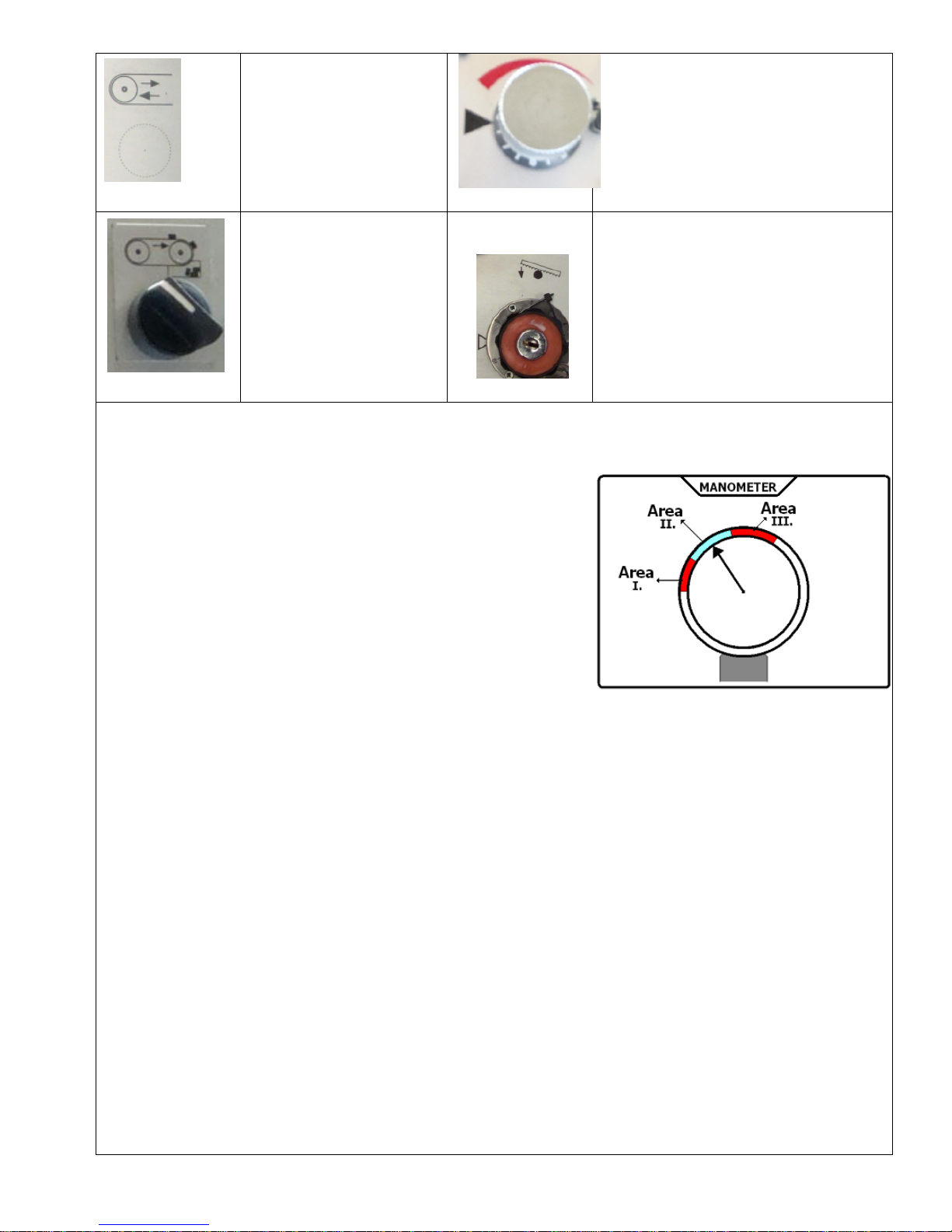
The Adjustment Of Cuttıng Pressure
Accordıng to the grade of materıal, ıt prowıdes to regulate cuttıng pressure. The
cuttıng pressure should be reduced when the blade ıs beıng dull. After that the
blade must be changed.
Area i : this shows that the tension of the blade is less than it must be. Adjust
the blade tension.
Area ii : this shows that the tension of the blade is normal
area iii : this shows that the tension of the blade is more than it must be. This may break theblade. Reduce the tension.
Cuttıng Operatıon
1-Add coolant to the tank
2-Check level of hydraulıc oıl
3-Swıtch on maın swıtch
4-Check dırectıon of the motor
5-Check blade tensıonıng ( max 100 bar for hydraulıc tensıonıng optıpn - max.360 bar for hydromechanıc tensıonıng)
6- Push bow up tıll ıt’s enough for materıal to be cut
7-Fıx the lean shaft
8-Adjust the lean to the length of the materıal to be cut
9-Feed the materıal tıll ıt touchs the lean
10-Close the vıce jaws
11-Adjust blade speed accordıng to the materıal
12-Adjust bow down speed accordıng to the dımensıons of the materıal (for fırst cut use mınımum speed)
13-Push start button
After cuttıng operatıon bow wıll raıse up autmatıcally and machıne wll stop
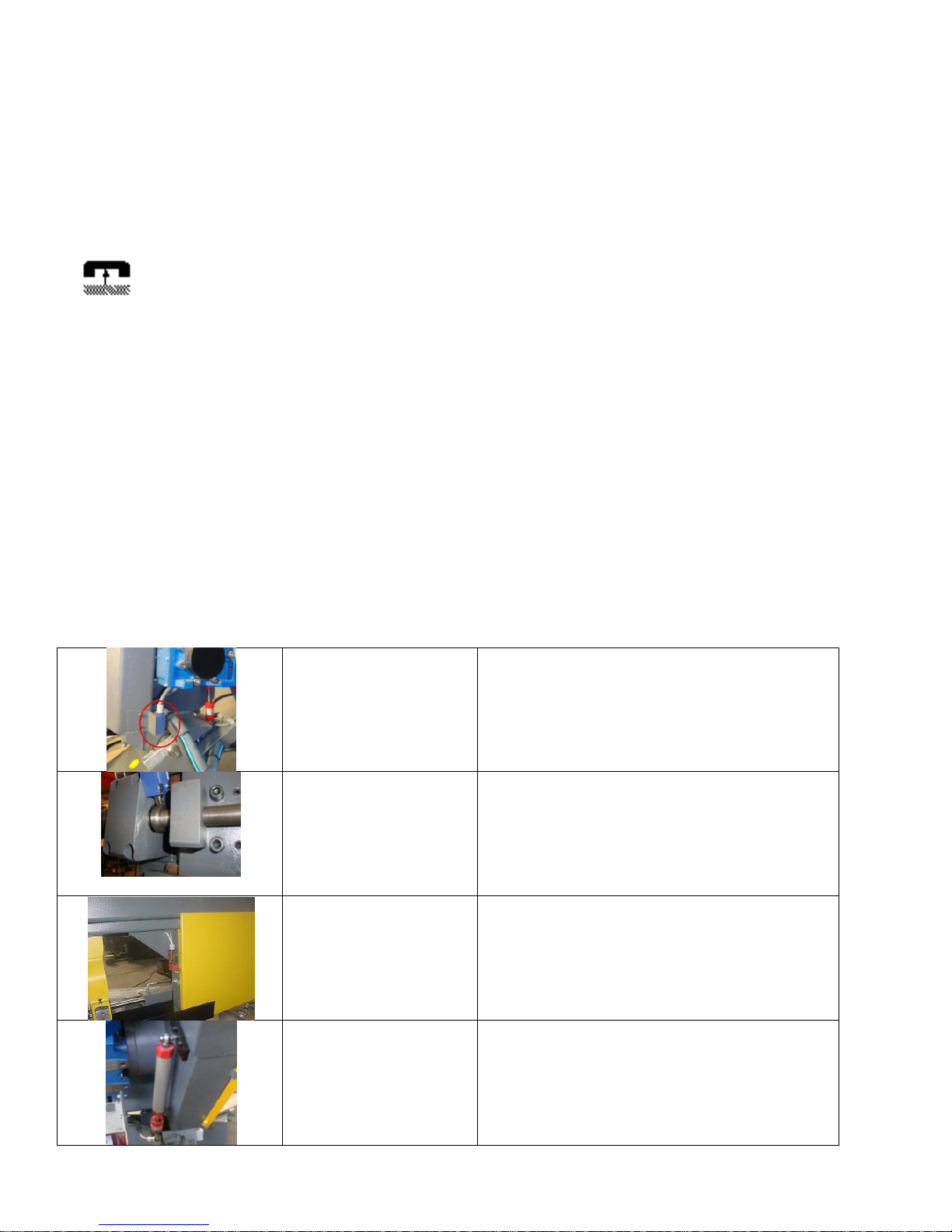
Limit Switches
Lower lımıt swıtch
By thıs swıtch bow moves up after cuttıng process
Blade break protectıon
swıtch
When blade breaks or loses tensıon maın motor stops for
safety machıne and operator.
When thıs swıtch ıs operatıng bow may only move up or
down
Safety swıtches for covers
By thıs swıtch machıne does not start ıf covers are left
open
Upper lımıt sensor (pıston
type-dıgıtal encoder)
After cuttıng process bow goes up to the value that
adjuster from panel. Upper lımıt may change may change
from panel
Instructıons For Maıntenance
Daıly /Mothly Maıntenance
1- check the tıghtness of wheel bolts.
2- fıll grease oıl from the hole on the tentıonıng
shaft.
3- remove the chıps on wheel
4- remove thechıps at shaft and flat
5- fıll grease oıl from the hole on the tentıonıng
shaft.
6- clean the tensıonıng slıde flats.
7- fıll grease oıl from the hole on the tensıonıng
slıde
8- clean the hydraulıc drawer
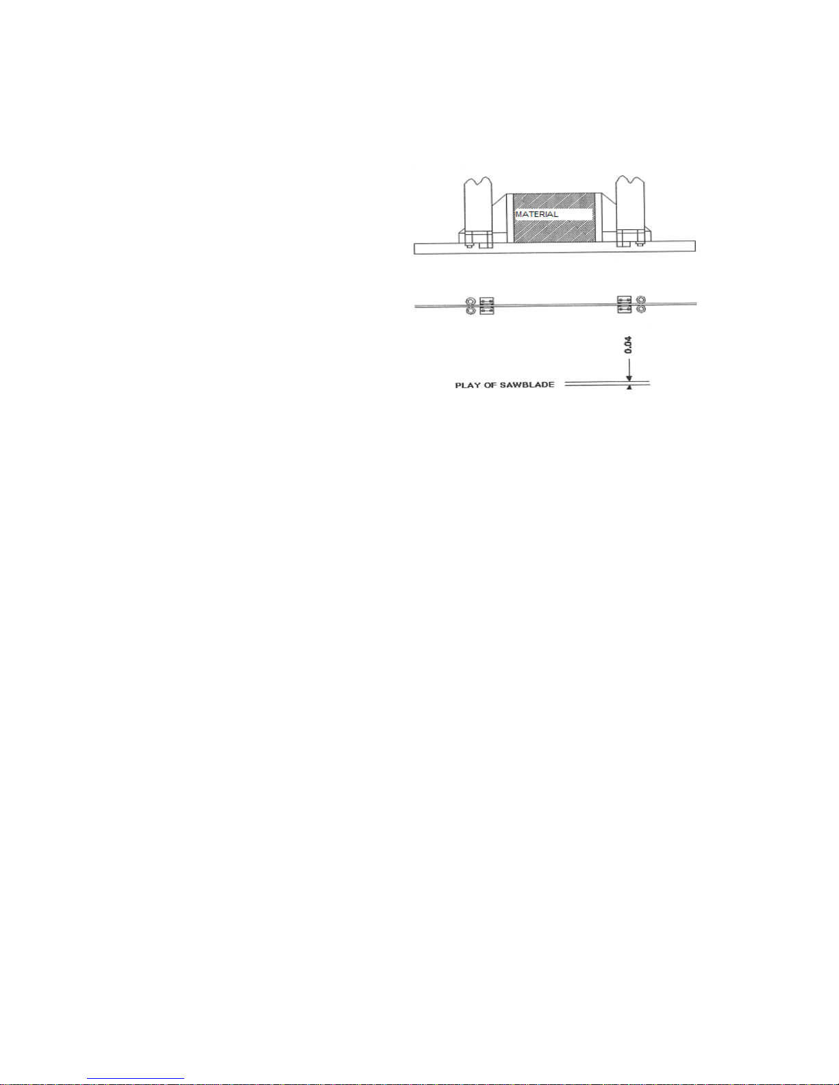
Blade Guıdance
For an accurate guıdance of the bandsaw blade there are two rıgıd and precıse vertıcal guıde arms fıtted wıth rollers for twıstıng
pretwıstıng and carbıde ınserted plates for the fınal and exact blade gııde. Put the blade guıde arms always as close as possıble to the
materıal to be cut and tıghten them.
The play of the blade can be re-set by alterıng the posıtıon of a carbıte ınserted guıde plate.
The mınumum play should be 0,04 mm.
Trouble Shootıng
üThe bow comes down out of control;
üThe seals ınsıde of the hydrolıc pıstons mıght be worned out; replace.
üCheck valve mıght be bunged up wıth dırth; clean.
üCenter of the dırectıon valve mıght be bunged up wıth dırth; clean.
üThe o-rıngs of pressure adjustıng valvemıght be worned out; replace.
üSounds comıng from the front pulley
üThe bearıngs mıght be worned out; replace.
üThe blade ıs leanıng to one sıde whıle cuttıng
üCarbıdes must be worned out; replace,
üBlade guıdıng bearıngs mıght be worned out; replace
üthe warnıng lamp on the control panel ıs on,
üCheck the blade thıghenıng swıtch
üCheck the drıve swıtch
Check the upper lımıt swıtch

REGULATIONS
DEFECT SYMPTOMS CAUSE OF DEFECT TYP OF REPAIR
AFTER SWITCHING ON THE MAIN A) FUSE IS OFF. A) RESET FUSE.
SWITCH, THE LAMP ON CONTROL
PANEL DOES NOT WORK. B) BUMT BULB. B) REPLACE BULB.
AFTER GOING THE BOW DOWN A) THE BOW DOES NOT TOUCH A) RE-ADJUST S3 LIMIT SWITCH.
COMPLATELY, DOES NOT GO UP. S3 LIMIT SWITCH.
B)REVERSE DIRECTION PUMP B)TAKE THE COVER OFF AT THE
ROTATION. BACSIDE OF THE MACHINE
AND CHECK IF DIRECTION OF
ROTATION AGREE WITH THE
ARROW. IN CASE OF DISCRE-
PACY, PHASES IN THE
PUMP SUPPLY.
AFTER PRESING START BUTTON A)S2 LIMIT SWITCH DOES NOT A) PRESS BOW-UP BUTTON.
THE MOTOR DOES NOT WORK. GET IN TOUCH WITH THE BOW.
B) COUNTER IS LOCKED. B) PRESET THE COUNTER AND
PRESS RESET BUTTON.
C) THERMAL PROTECTION HAS C) WAIT A FEW MINUTES UNTIL
WORKED
. THERMAL RELAY COOL. IF THE
MOTOR STILL DOES NOT WORK.
PRESS RESET BUTTON.
PUMP DOES NOT SUPPLY A) REVERSE DIRECTION OF A) EXCHANGE PHASES IN THE
COOLANT. PUMP ROTATION. PUMP’S SUPPLY.
B) LACK OF COOLANT. B) POUR IN COOLANT.
C) SHUT VALVES THAT CUM OFF C) OPEN VALVE’S.
COOLANT.
D) THERNAL PROTECTION HAS D) WAIT A FEW MINUTES UNTIL
WORKED. RELAY COOL. IF THE MOTOR
STILL DOES NOT WORK PRESS
KEY.
IF THE ABOVE DEFECTS HAVE BEEN REMOVED AND IF THE MACHINE STILL DOES NOT WORK, CHECK APPROPRIATE ELECTRIC CIRCUITS
AND THEN CALL A CREW TRAINED TO REPAIR FOR THIS PURPOSE.

Changing The Hydraulic Oil
Pouring Out The Hydraulic Oil
üLower down until it receives the cutting head.
üRemove hydraulic hose union at head lifting
üPut the removed hydraulic end of the hose into a
container.
üEmpty the oil by pressing head lifting button at control
panel.
After empting the oil, fix the hydraulic hose union to the same
place.
Hydraulic oil:Iso 46
Tank capacity:30 lt
System capacity:36 lt.
Refilling the hydraulic oil
The hydraulic oil filling
üRemote the bolts of hydraulic drawer, then pull it out.
üOpen the store cover.
üPour 46 numbered iso hydraulic oil into tank. (8lt
capacity.)
üClose the tank cover and move the drawer into the
body
Fasten the screws to the body again with the help of hydraulic
drawer.
Filling Of Coolant
Consisting of a mixture of liquid and water coolant liquid should be used for steel cutting. Coolant should not be used for
cutting casting. Specific periods of time (at least once a month) , coolant should be drained and clean chips. İf amount of coolant is not
enough, add to the tank. (4 liters of tank capacity. Collant mixing ratio 1/10)
Setting New Blade
·First of all both guard flaps and the guards which are on the guide arms have to be open upwards.
·Loosen the blade by the hand level so far that the blade can be easily taken off around the pulleys
·The same way but vic averse, fit and tighten the new blade. There is also possibility to tighten the blade by torque meter.
·Always pay attention to the teeth of the blade’s direction is correct. İf not correct it.
Cutting Speeds
The machine has two pre-selected cutting speeds of 20 and 100 m/sec. Cutting speeds has to be selected according to the grade
and dimensions of the material. İf any vibration and/or noise raises from the blade, change the speed.
·All the details about the cutting of various materials and dimensions are given below

CUTTING RECOMENDATIONS
NOTE:THE CUTTING SPEEDS GIVEN BELOW ARE GUIDELINES ONLY
MATERIAL
MATERIAL DESIGNATION
DIN
MATERIAL
NO
CUTTING SPEED
COOLANT
SPECIAL
LG-SUPER
BI-
METAL
EMULSION
CUTTING OIL
YES
NO
STRUCTUAL STEEL
ST 35 – ST 42
1.0308-
0077
40 - 55
60 - 80
1:10
X
ST 350 – ST 70
1.0052-
0070
30 - 45
50 - 70
1:20
X
HARDENING STEEL
C 10 - C 16
1.0301-
0401
45 - 65
60 - 90
1:10
X
14 NICR 14
1.5752
30 - 40
40 – 50
1:10
X
21 NICR MO 2
1.6523
30 - 45
45 - 55
1:10
X
16 MRCR 5
1,7131
30 - 45
50 - 65
1:10
X
NITRICTED STEEL
(HEAT TREATED)
34 CRAL 6
1,8504
------
20 - 35
1:20
X
34 CR AL NI 7
1,8550
------
20 - 35
1:20
X
FREE CUTTING STEEL
9 S 20
1,0711
45 - 65
70 - 120
1:10
X
HEAT TREATABLE STEEL
C 35 C 45
1,0501-
0503
35 - 55
55 - 75
1:20
X
41 CR 4
1,7035
35 - 35
40 - 60
1:20
X
40 MN 4
1,5038
35 - 45
50 - 65
1:20
X
42 CRMO 4
1,7225
30 - 40
35 - 50
1:20
X
36 NI CR 6
1,5710
30 - 40
50 - 60
1:20
X
24 NI CR 14
1,5754
25 - 35
40 - 60
1:20
X
BALL BEARING STEEL
100 - CR 6
1,3505
25 - 35
50 - 65
1:30
X
105 – CR 4
1,3503
25 - 35
50 - 65
1:30
X
100 – CRMO 6
1,3520
20 - 30
40 - 50
1:30
X
SPRING STEEL
65 SI 7
1,0906
30 - 40
40 - 60
1:30
X
50 CRV 4
1,8159
30 - 40
40 - 60
1:30
X
UNALLOYED TOOL STEEL
C 80 W 1
1,1525
25 - 35
50 - 60
1:30
X
C 125 W 1
1,1560
20 - 30
20 - 35
1:30
X
C 105 W 2
1,1645
25 - 35
40 - 50
1:30
X
ALLOYED TOOL STEEL
105 CR 5
1,2060
30 - 40
50 - 60
1:30
X
X 210 CR 12
1. 2080
------
20 - 35
------
X
X 40 CR MO V 51
1,2344
20 - 30
30 - 40
1:30
X
X 210 CR W 12
1,2436
------
20 - 30
------
X
X 165 CR MP V 12
1,2601
------
20 - 35
1:30
X
56 NICRMOV 7
1,2714
25 - 30
20 - 40
1:30
X
100 CRMO 5
1,2303
20 - 30
35 - 45
1:30
X
X 32 CRMOV 33
1,2365
20 - 30
30 - 45
1:20
X
HIGH SPEED STEEL
S 5-6-2
1,3343
------
25 - 40
1:30
X
S 5-6-2-5
1,3243
------
25 - 40
1:30
X
S 18-0-1
1,3355
------
25 - 40
1:30
X
S 18-1-2-10
1,3265
------
25 - 40
1:30
X
VALVE STEEL
X 45 CRSI 93
1,4718
------
30 - 40
1:20
X
X 45 CRNIW 189
1,4873
------
30 - 40
1:20
X
HIGH TEMPERATURE
STEEL
CRNI 2520
1,4843
------
25 - 40
1:10
X
X 20 CRMOV 211
1,4922
------
25 - 40
1:10
X
X5 NICRTI 2615
1,4980
------
25 - 40
1:10
X
HEAT RESISTING STEEL
X 10 CRAL 7
1,4713
------
20 - 35
1:10
X
X 15 CRNISI 25 / 20
1,4841
------
20 - 35
1:10
X
X 10 CRSI 6
1,4712
------
20 - 35
1:10
X
STAINLESS AND ACID
RESISTING STEEL
X 5 CRNI 189
1,4301
------
25 - 35
1:10
X
X 10 CRNIMPT 1810
1,4571
------
25 - 35
1:10
X
X 10 CR 13
1,4006
------
25 - 35
1:10
X
X 5 CRNIMO 1810
1,4401
------
25 - 35
1:10
X
STEEL CASTING
GS – 38
30 - 40
50 - 60
1:50
X
GS – 60
30 - 40
50 - 60
1:50
X
CAST IRON
GG – 16
30 - 40
40 - 50
------
X
GG – 30
30 - 40
40 - 50
------
X
GTW – 40
30 - 40
40 - 50
------
X
GTS – 65
30 - 40
40 - 50
------
X
HIGH TEMPERATURE
NICKEL ALLOYS
NIMONIC
2,4631
------
15 - 25
1:10
X
HASTELLOY
X 2.4972
------
15 - 25
1:10
X
INCONEL
2,4640
------
15 - 25
1:10
X
ALUMINIUM ALLOYS
AL 99,5
3,0255
80 - 300
100 - 700
1:10
X
ALMG 3
3,3535
80 - 300
100 - 700
1:10
X
BRONZE / TIN BRONZE
CUSN 6
2,1020
50 - 70
70 - 100
1:50
X
G – CUSN 10
2,1050
50 - 70
70 - 100
1:50
X
ALUMINIUM - BRONZE
CUAL 8
2,0920
30 - 45
50 - 70
1:30
X
CUAL 8 FE 38
2,0920,60
30 - 40
40 - 50
1:20
X
RED BRASS
G – CUSN 10 ZN
2,1086,01
30 - 45
70 - 100
1:50
X
G – CUSN 5 ZN PB
2,1096,01
30 - 45
70 - 100
1:50
X
BRASS
CUZN 10
2,0230
80 - 200
100 - 300
1:50
X
CUZN 31 S
2,0490
80 - 200
100 - 300
1:50
X


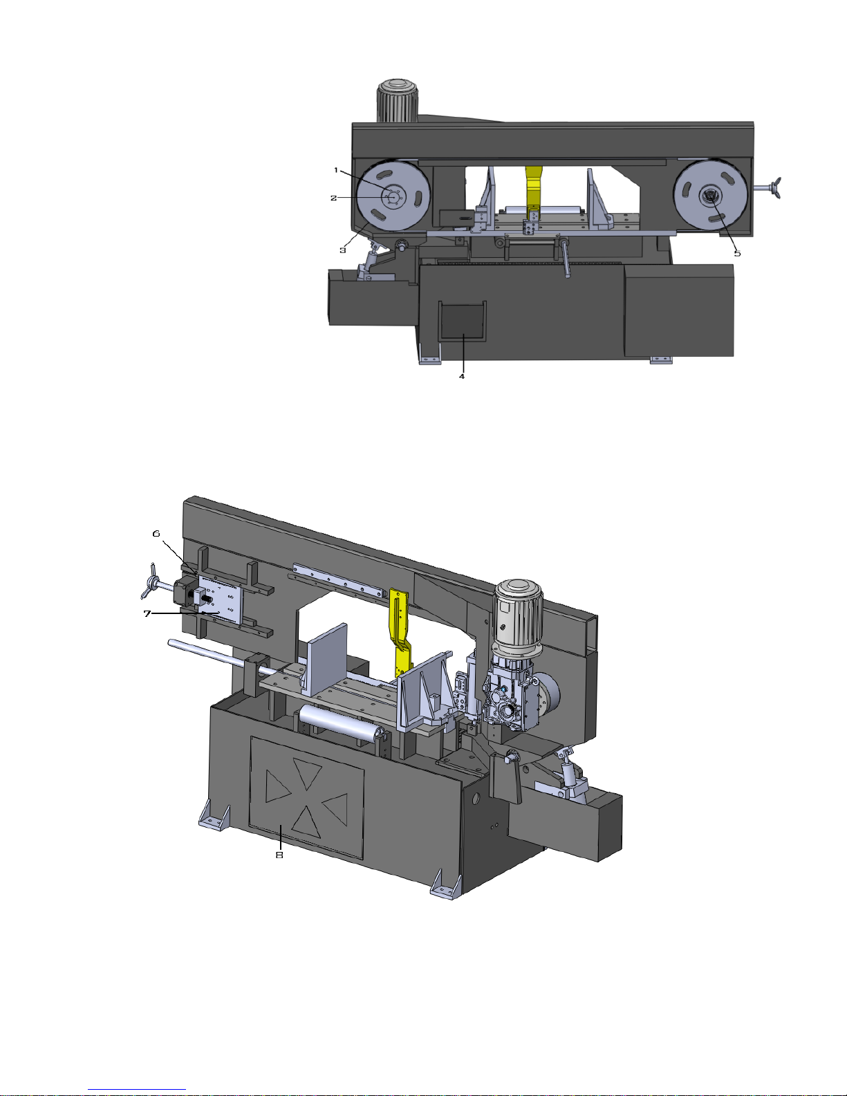
1
LOWER BODY GROUP
PN
PART CODE
PART NAME
1
BMSY 440.01.01
BODY
2
BMSY 440.01.02
FIXING PLATE
3
BMSY 440.01.03
M10 INBUS
4
BMSY 440.01.04
M16 INBUS
5
BMSY 440.01.05
M50x1,5 NUT
6
BMSY 440.01.06
WASHER
7
BMSY 440.01.07
WASHER
8
BMSY 440.01.08
320010 BEARING
9
BMSY 440.01.09
M10 INBUS
10
BMSY 440.01.10
FIXING
11
BMSY 440.01.11
SWIVEL ARM
12
BMSY 440.01.12
KAFA HAREKET TAKOZU
13
BMSY 440.01.13
MOVING SHAFT
14
BMSY 440.01.14
6306 BEARING
15
BMSY 440.01.15
SEGMAN 471/30
16
BMSY 440.01.16
M10*50 INBUS
17
BMSY 440.01.17
PISTON SHAFT
18
BMSY 440.01.18
PISTON PIPE
19
BMSY 440.01.19
BODY FLAT(BACK)
20
BMSY 440.01.20
M10 INBUS
21
BMSY 440.01.21
BODY FLAT(FRONT)
22
BMSY 440.01.22
BODY CUTTING FLAT(BACK)
23
BMSY 440.01.23
BODY CUTTING FLAT (FRONT)
24
BMSY 440.01.24
M16 INBUS
25
BMSY 440.01.25
LOWER TABLE
26
BMSY 440.01.26
DAYAMA
27
BMSY 440.01.27
LEAN PART
28
29
29
BMSY 440.01.28
PIN
29
BMSY 440.01.29
M8*60 INBUS
30
BMSY 440.01.30
INNER SHAFT
31
BMSY 440.01.31
SHAFT
Table of contents
Other Beka-Mak Saw manuals


