YASKAWA PS M07 User manual

PS | M07-2BA00 | Manual
HB400 | PS | M07-2BA00 | en | 20-02
VIPA System MICRO
Power supply - PS M07

M07-2BA00_000_PS M07,1,EN - © 2020
YASKAWA Europe GmbH
Ohmstraße 4
91074 Herzogenaurach
Tel.: +49 9132 744 0
Fax: +49 9132 744 186
Email: [email protected]
Internet: www.yaskawa.eu.com

Table of contents
1 General.................................................................................................................... 4
1.1 Copyright © YASKAWA Europe GmbH............................................................ 4
1.2 About this manual............................................................................................. 6
1.3 Safety instructions............................................................................................ 7
2 Basics and mounting............................................................................................. 8
2.1 Safety information for users.............................................................................. 8
2.2 System conception........................................................................................... 9
2.3 Dimensions..................................................................................................... 10
2.4 Mounting......................................................................................................... 12
2.4.1 Mounting without mounting rail.................................................................... 13
2.4.2 Mounting with mounting rail......................................................................... 13
2.5 Wiring............................................................................................................. 15
2.5.1 Wiring power supply.................................................................................... 15
2.6 Demounting.................................................................................................... 16
2.7 Installation guidelines..................................................................................... 19
2.8 General data................................................................................................... 21
3 Power supply........................................................................................................ 23
3.1 Safety instructions.......................................................................................... 23
3.2 PS M07 DC24V, 1.5A_AC120V-240V............................................................ 24
3.3 Technical data................................................................................................. 27
Appendix............................................................................................................... 29
A History of changes............................................................................................ 31
VIPA System MICRO Table of contents
HB400 | PS | M07-2BA00 | en | 20-02 3

1 General
1.1 Copyright © YASKAWA Europe GmbH
This document contains proprietary information of YASKAWA and is not to be disclosed
or used except in accordance with applicable agreements.
This material is protected by copyright laws. It may not be reproduced, distributed, or
altered in any fashion by any entity (either internal or external to YASKAWA) except in
accordance with applicable agreements, contracts or licensing, without the express
written consent of YASKAWA and the business management owner of the material.
For permission to reproduce or distribute, please contact: YASKAWA Europe GmbH,
European Headquarters, Hauptstraße 185, 65760 Eschborn, Germany
Tel.: +49 6196 569 300
Fax.: +49 6196 569 398
Email: [email protected]
Internet: www.yaskawa.eu.com
Every effort has been made to ensure that the information contained in
this document was complete and accurate at the time of publishing. Nev-
ertheless, the authors retain the right to modify the information.
This customer document describes all the hardware units and functions
known at the present time. Descriptions may be included for units which
are not present at the customer site. The exact scope of delivery is
described in the respective purchase contract.
Hereby, YASKAWA Europe GmbH declares that the products and systems are in compli-
ance with the essential requirements and other relevant provisions. Conformity is indi-
cated by the CE marking affixed to the product.
For more information regarding CE marking and Declaration of Conformity (DoC), please
contact your local representative of YASKAWA Europe GmbH.
VIPA, SLIO, System 100V, System 200V, System 300V, System 300S, System 400V,
System 500S and Commander Compact are registered trademarks of YASKAWA Europe
GmbH.
SPEED7 is a registered trademark of YASKAWA Europe GmbH.
SIMATIC, STEP, SINEC, TIA Portal, S7-300, S7-400 and S7-1500 are registered trade-
marks of Siemens AG.
Microsoft and Windows are registered trademarks of Microsoft Inc., USA.
Portable Document Format (PDF) and Postscript are registered trademarks of Adobe
Systems, Inc.
All other trademarks, logos and service or product marks specified herein are owned by
their respective companies.
All Rights Reserved
EC conformity declaration
Conformity Information
Trademarks
VIPA System MICRO
General
Copyright © YASKAWA Europe GmbH
HB400 | PS | M07-2BA00 | en | 20-02 4

Contact your local representative of YASKAWA Europe GmbH if you have errors or ques-
tions regarding the content of this document. If such a location is not available, you can
reach YASKAWA Europe GmbH via the following contact:
YASKAWA Europe GmbH, Ohmstraße 4, 91074 Herzogenaurach, Germany
Fax: +49 9132 744 29 1204
Email: [email protected]
Contact your local representative of YASKAWA Europe GmbH if you encounter problems
or have questions regarding the product. If such a location is not available, you can reach
the YASKAWA customer service via the following contact:
YASKAWA Europe GmbH,
European Headquarters, Hauptstraße 185, 65760 Eschborn, Germany
Tel.: +49 6196 569 500 (hotline)
Email: [email protected]
Document support
Technical support
VIPA System MICRO General
Copyright © YASKAWA Europe GmbH
HB400 | PS | M07-2BA00 | en | 20-02 5
1.2 About this manual
The manual describes the power supply (PS) that can be used in the VIPA System
MICRO. Described are construction, application and technical data.
Product Order no. as of HW state:
PS M07 DC24V, 1.5A_AC120V-240V M07-2BA00 01
The manual is targeted at users who have a background in automation technology.
The manual consists of chapters. Every chapter provides a self-contained description of a
specific topic.
The following guides are available in the manual:
nAn overall table of contents at the beginning of the manual
nReferences with page numbers
The manual is available in:
nprinted form, on paper
nin electronic form as PDF-file (Adobe Acrobat Reader)
Important passages in the text are highlighted by following icons and headings:
DANGER!
Immediate or likely danger. Personal injury is possible.
CAUTION!
Damages to property is likely if these warnings are not heeded.
Supplementary information and useful tips.
Objective and contents
Target audience
Structure of the manual
Guide to the document
Availability
Icons Headings
VIPA System MICRO
General
About this manual
HB400 | PS | M07-2BA00 | en | 20-02 6

1.3 Safety instructions
DANGER!
There is a warning symbol on the housing of the power supply. This indi-
cates that all safety instructions listed in this manual must be observed
before commissioning!
DANGER!
Failure to comply with the specification may affect the protective functions
of the system!
The power supply is constructed and produced for:
nthe DC 24V supply of components.
noperation within the environmental conditions specified in the technical data
nthe installation on a 35mm mounting rail in a control cabinet, which provides protec-
tion against fire, environmental influences and mechanical impact
nindustrial applications
DANGER!
This device is not certified for applications in
– in explosive environments (EX-zone)
The manual must be available to all personnel in the
nproject design department
ninstallation department
ncommissioning
noperation
CAUTION!
The following conditions must be met before using or commis-
sioning the components described in this manual:
– Hardware modifications should only be carried out when the system
has been disconnected from power!
– Installation and hardware modifications only by properly trained per-
sonnel.
– The national rules and regulations of the respective country must be
satisfied (installation, safety, EMC ...)
National rules and regulations apply to the disposal of the unit!
Warning symbol on the
housing
Intended use
Documentation
Disposal
VIPA System MICRO General
Safety instructions
HB400 | PS | M07-2BA00 | en | 20-02 7
2 Basics and mounting
2.1 Safety information for users
VIPA modules make use of highly integrated components in MOS-Technology. These
components are extremely sensitive to over-voltages that can occur during electrostatic
discharges. The following symbol is attached to modules that can be destroyed by elec-
trostatic discharges.
The Symbol is located on the module, the module rack or on packing material and it indi-
cates the presence of electrostatic sensitive equipment. It is possible that electrostatic
sensitive equipment is destroyed by energies and voltages that are far less than the
human threshold of perception. These voltages can occur where persons do not dis-
charge themselves before handling electrostatic sensitive modules and they can damage
components thereby, causing the module to become inoperable or unusable. Modules
that have been damaged by electrostatic discharges can fail after a temperature change,
mechanical shock or changes in the electrical load. Only the consequent implementation
of protection devices and meticulous attention to the applicable rules and regulations for
handling the respective equipment can prevent failures of electrostatic sensitive modules.
Modules must be shipped in the original packing material.
When you are conducting measurements on electrostatic sensitive modules you should
take the following precautions:
nFloating instruments must be discharged before use.
nInstruments must be grounded.
Modifying electrostatic sensitive modules you should only use soldering irons with
grounded tips.
CAUTION!
Personnel and instruments should be grounded when working on electro-
static sensitive modules.
Handling of electrostatic
sensitive modules
Shipping of modules
Measurements and altera-
tions on electrostatic sen-
sitive modules
VIPA System MICRO
Basics and mounting
Safety information for users
HB400 | PS | M07-2BA00 | en | 20-02 8

2.2 System conception
The System MICRO is a modular automation system for assembly on a 35mm mounting
rail. By means of periphery modules this system may be adapted matching to your auto-
mation tasks. In addition, it is possible to expand your CPU by appropriate interfaces. The
wiring complexity is low, because the DC 24V electronic section supply is integrated to
the backplane bus and this allows replacement with standing wire.
nCPU
nExtension module
nPeriphery module
With the CPU electronic, input/output components and power supply are integrated to
one casing. In addition, up to 8 periphery modules of the System MICRO can be con-
nected to the backplane bus. As head module via the integrated power module for power
supply CPU electronic and the I/O components are supplied as well as the electronic of
the periphery modules, which are connected via backplane bus. To connect the power
supply of the I/O components and for DC 24V electronic power supply of the periphery
modules, which are connected via backplane bus, the CPU has removable connectors.
By installing of up to 8 periphery modules at the backplane bus of the CPU, these are
electrically connected, this means these are assigned to the backplane bus and con-
nected to the DC 24V electronic power supply.
By using extension modules you can extend the interfaces of the CPU. The attachment to
the CPU is made by plugging on the left side of the CPU. You can only connect one
extension module to the CPU at a time.
Overview
Components
CPU
Extension module
VIPA System MICRO Basics and mounting
System conception
HB400 | PS | M07-2BA00 | en | 20-02 9

The power supply is mounted on the left side from the DIN rail with the System MICRO
modules. It serves for electronics and power supply.
By means of up to 8 periphery modules, you can extend the internal I/O areas. The
attachment to the CPU is made by plugging them on the right side of the CPU.
2.3 Dimensions
Dimensions in mm
Power supply
Periphery module
Dimensions CPU M13C
VIPA System MICRO
Basics and mounting
Dimensions
HB400 | PS | M07-2BA00 | en | 20-02 10

Dimensions in mm
Dimensions extension
module EM M09
Dimensions power supply
VIPA System MICRO Basics and mounting
Dimensions
HB400 | PS | M07-2BA00 | en | 20-02 11
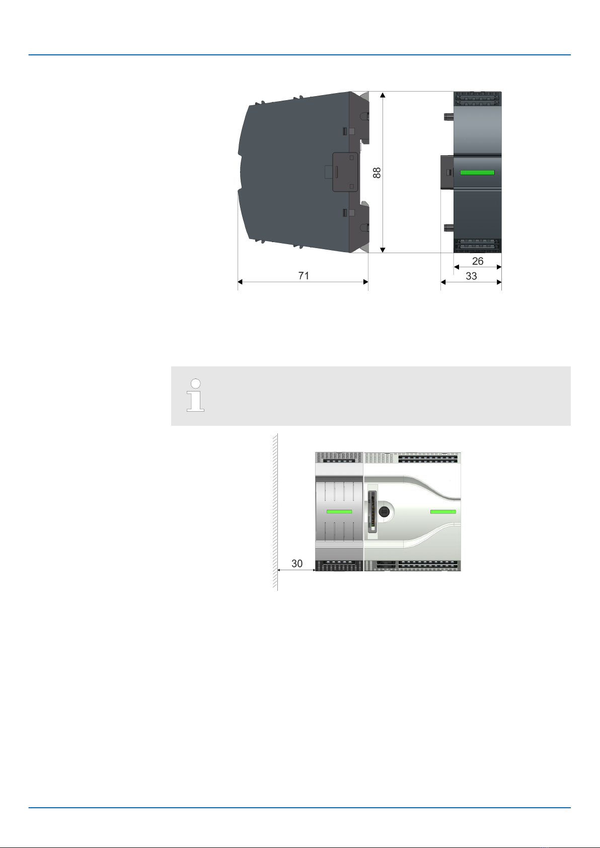
Dimensions in mm
2.4 Mounting
Observe minimum distance!
For operation within the specified nominal values, they must comply with
a minimum distance of 30 mm on one side of the module!
Dimensions in mm
Dimensions periphery
module
VIPA System MICRO
Basics and mounting
Mounting
HB400 | PS | M07-2BA00 | en | 20-02 12

2.4.1 Mounting without mounting rail
You can screw the power supply to the back wall by means of screws via the locking
levers. The happens with the following proceeding:
Dimensions in mm
1. The power supply has a locking lever on the upper and lower side. Pull these levers
outwards as shown in the figure, until these engage 2x audible.
ðBy this openings on the locking levers get visible.
2. Use this openings to fix your power supply to your back wall with appropriate
screws. Consider the installation clearances for the power supply.
ðThe power supply is now mounted and can be wired.
2.4.2 Mounting with mounting rail
Dimensions in mm
1. Mount the mounting rail. Please consider that a clearance from the middle of the
mounting rail of at least 44mm respectively 55mm above and below exists.
Proceeding
Proceeding
VIPA System MICRO Basics and mounting
Mounting > Mounting with mounting rail
HB400 | PS | M07-2BA00 | en | 20-02 13
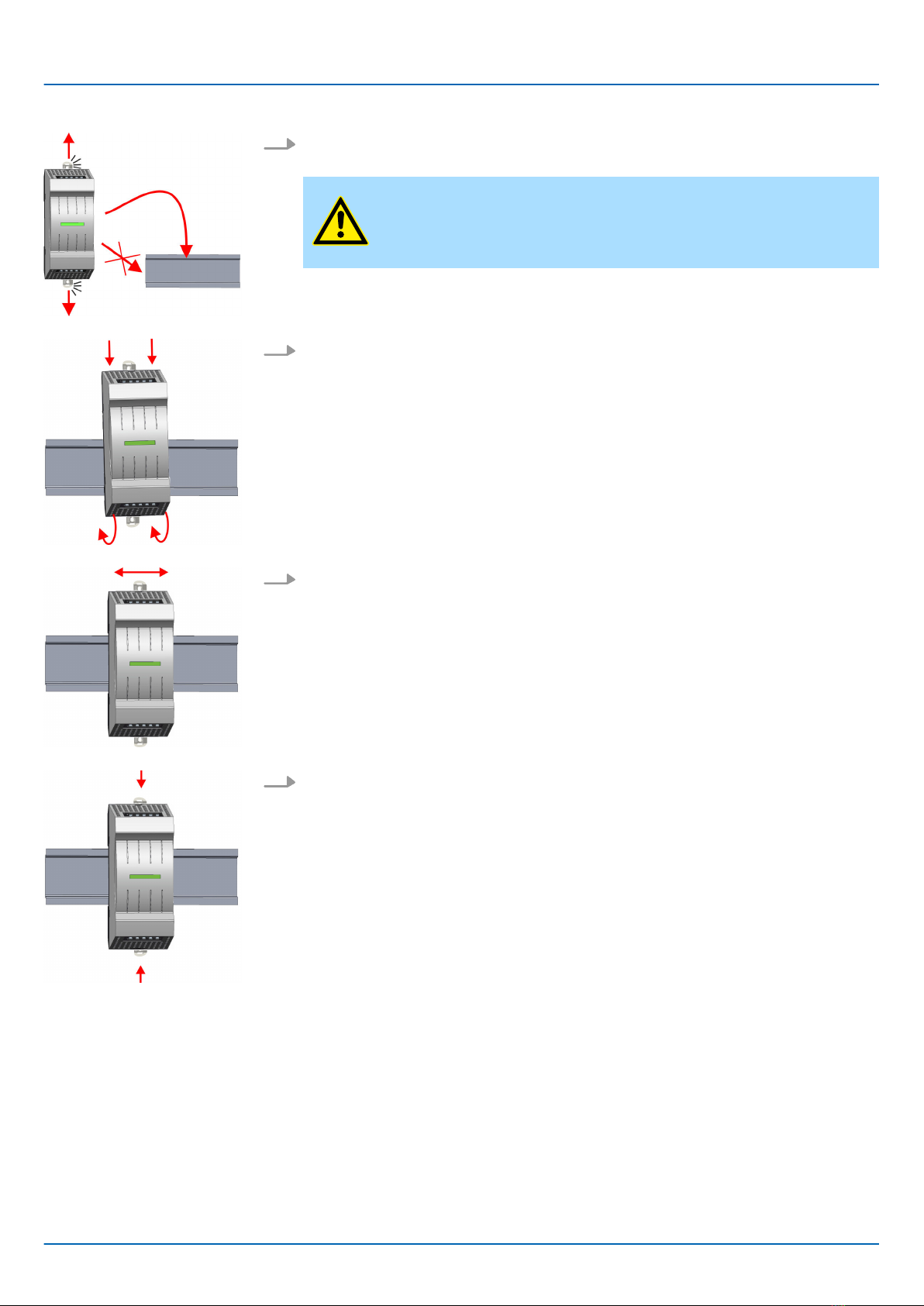
2. The power supply has a locking lever on the upper and lower side. Pull these levers
outwards as shown in the figure, until these engage audible.
CAUTION!
It is not allowed to mount the module sideways on the mounting rail,
as otherwise the module may be damaged.
3. Plug the power supply from the top onto the mounting rail and turn the power supply
downward until it rests on the mounting rail.
4. Move the power supply on the mounting rail at its position.
5. To fix the power supply at the mounting rail, move the locking levers back to the ini-
tial position.
ðThe power supply is now mounted and can be wired.
VIPA System MICRO
Basics and mounting
Mounting > Mounting with mounting rail
HB400 | PS | M07-2BA00 | en | 20-02 14

2.5 Wiring
DANGER!
Consider strain relief of the supply lines!
Since the plug for the supply lines of the input voltage has no (double)
insulation, not permanently fixed supply lines must be relieved from push
and pull!
CAUTION!
Consider temperature for external cables!
Cables may experience temperature increase due to system heat dissi-
pation. Thus the cabling specification must be chosen 25°C above
ambient temperature!
CAUTION!
Separate insulation areas!
The system is specified for SELV/PELV environment. Devices, which are
attached to the system must meet theses specifications. Installation and
cable routing other than SELV/PELV specification must be separated
from the system’s equipment!
2.5.1 Wiring power supply
For wiring the power supply has removable connectors. With the wiring of the connectors
a "push-in" spring-clip technique is used. This allows a quick and easy connection of your
supply lines. The clamping off takes place by means of a screwdriver.
Umax 240V AC / 30V DC
Imax 2A
Cross section 0.2 ... 1.5mm2 (AWG 24 ... 16)
Stripping length 10mm
Use for wiring rigid wires respectively use wire sleeves. When using stranded wires you
have to press the release button with a screwdriver during the wiring.
1 Labeling on the casing
2 Release area
3 Connection hole for wire
4 Pin 1 of the connector is labelled by a white line.
Connectors
Data
Wiring procedure
VIPA System MICRO Basics and mounting
Wiring > Wiring power supply
HB400 | PS | M07-2BA00 | en | 20-02 15
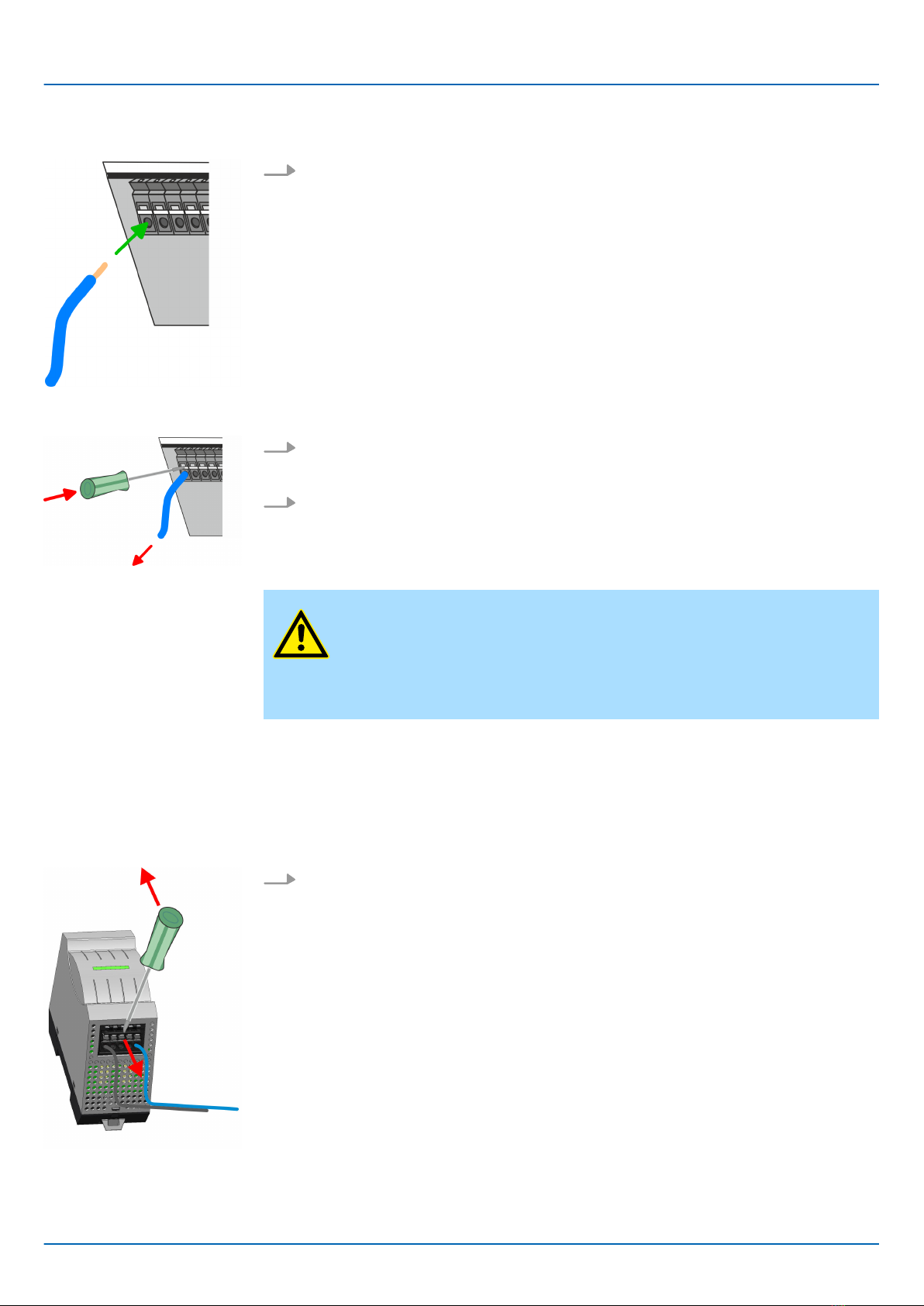
The wiring happens without a tool.
Determine according to the casing labelling the connection position and insert
through the round connection hole of the according contact your prepared wire until
it stops, so that it is fixed.
ðBy pushing the contact spring opens, thus ensuring the necessary contact pres-
sure.
The wire is to be removed by means of a screwdriver with 2.5mm blade width.
1. Press with your screwdriver vertically at the release button.
ðThe contact spring releases the wire.
2. Pull the wire from the round hole.
CAUTION!
To protect the power supply lines, you should use a circuit breaker with
the following characteristics:
– Rated current at AC 230V: 4A
– Tripping characteristic: C
2.6 Demounting
By means of a screwdriver there is the possibility to remove the connectors e.g. for
module exchange with a fix wiring. For this each connector has indentations for unlocking
at the top. Unlocking takes place by the following proceeding:
1. Remove connector:
Insert your screwdriver from above into one of the indentations.
Insert wire
Remove wire
Fusing
Remove connector
VIPA System MICRO
Basics and mounting
Demounting
HB400 | PS | M07-2BA00 | en | 20-02 16

2. Push the screwdriver backwards:
ðThe connector is unlocked and can be removed.
CAUTION!
Via wrong operation such as pressing the screwdriver down-
ward, the release lever may be damaged.
3. In this way, remove all plugged connectors on the power supply.
The replacement of the power supply on the mounting rail happens with the following pro-
ceeding:
1. Use a screwdriver to pull the locking levers of the power supply outwards until these
engage audible.
2. Remove the power supply with a rotation upwards from the mounting rail.
3. Pull the locking levers of the new power supply outwards until these engage
audible. Plug the power supply from the top onto the mounting rail and turn the
power supply downward until it rests on the mounting rail.
CAUTION!
It is not allowed to mount the module sideways on the mounting rail,
as otherwise the module may be damaged!
Power supply replacement
Replacement on mounting
rail
VIPA System MICRO Basics and mounting
Demounting
HB400 | PS | M07-2BA00 | en | 20-02 17

4. Move the power supply on the mounting rail at its position.
5. To fix the power supply at the mounting rail, move the locking levers back to the ini-
tial position.
ðThe power supply is now mounted and can be wired.
1. Remove the connectors, which are not necessary at the power supply.
2. Plug again the wired connectors.
ðNow you can bring your system back into operation.
Plug connector
VIPA System MICRO
Basics and mounting
Demounting
HB400 | PS | M07-2BA00 | en | 20-02 18

2.7 Installation guidelines
The installation guidelines contain information about the interference free deployment of a
PLC system. There is the description of the ways, interference may occur in your PLC,
how you can make sure the electromagnetic compatibility (EMC), and how you manage
the isolation.
Electromagnetic compatibility (EMC) means the ability of an electrical device, to function
error free in an electromagnetic environment without being interfered respectively without
interfering the environment.
The VIPA components are developed for the deployment in industrial environments and
meets high demands on the EMC. Nevertheless you should project an EMC planning
before installing the components and take conceivable interference causes into account.
Electromagnetic interferences may interfere your control via different ways:
nElectromagnetic fields (RF coupling)
nMagnetic fields with power frequency
nBus system
nPower supply
nProtected earth conductor
Depending on the spreading medium (lead bound or lead free) and the distance to the
interference cause, interferences to your control occur by means of different coupling
mechanisms.
There are:
ngalvanic coupling
ncapacitive coupling
ninductive coupling
nradiant coupling
In the most times it is enough to take care of some elementary rules to guarantee the
EMC. Please regard the following basic rules when installing your PLC.
nTake care of a correct area-wide grounding of the inactive metal parts when installing
your components.
– Install a central connection between the ground and the protected earth conductor
system.
– Connect all inactive metal extensive and impedance-low.
– Please try not to use aluminium parts. Aluminium is easily oxidizing and is there-
fore less suitable for grounding.
nWhen cabling, take care of the correct line routing.
– Organize your cabling in line groups (high voltage, current supply, signal and data
lines).
– Always lay your high voltage lines and signal respectively data lines in separate
channels or bundles.
– Route the signal and data lines as near as possible beside ground areas (e.g.
suspension bars, metal rails, tin cabinet).
General
What does EMC mean?
Possible interference
causes
Basic rules for EMC
VIPA System MICRO Basics and mounting
Installation guidelines
HB400 | PS | M07-2BA00 | en | 20-02 19

nProof the correct fixing of the lead isolation.
– Data lines must be laid isolated.
– Analog lines must be laid isolated. When transmitting signals with small ampli-
tudes the one sided laying of the isolation may be favourable.
– Lay the line isolation extensively on an isolation/protected earth conductor rail
directly after the cabinet entry and fix the isolation with cable clamps.
– Make sure that the isolation/protected earth conductor rail is connected impe-
dance-low with the cabinet.
– Use metallic or metallised plug cases for isolated data lines.
nIn special use cases you should appoint special EMC actions.
– Consider to wire all inductivities with erase links.
– Please consider luminescent lamps can influence signal lines.
nCreate a homogeneous reference potential and ground all electrical operating sup-
plies when possible.
– Please take care for the targeted employment of the grounding actions. The
grounding of the PLC serves for protection and functionality activity.
– Connect installation parts and cabinets with your PLC in star topology with the
isolation/protected earth conductor system. So you avoid ground loops.
– If there are potential differences between installation parts and cabinets, lay suffi-
ciently dimensioned potential compensation lines.
Electrical, magnetically and electromagnetic interference fields are weakened by means
of an isolation, one talks of absorption. Via the isolation rail, that is connected conductive
with the rack, interference currents are shunt via cable isolation to the ground. Here you
have to make sure, that the connection to the protected earth conductor is impedance-
low, because otherwise the interference currents may appear as interference cause.
When isolating cables you have to regard the following:
nIf possible, use only cables with isolation tangle.
nThe hiding power of the isolation should be higher than 80%.
nNormally you should always lay the isolation of cables on both sides. Only by means
of the both-sided connection of the isolation you achieve high quality interference
suppression in the higher frequency area. Only as exception you may also lay the iso-
lation one-sided. Then you only achieve the absorption of the lower frequencies. A
one-sided isolation connection may be convenient, if:
– the conduction of a potential compensating line is not possible.
– analog signals (some mV respectively µA) are transferred.
– foil isolations (static isolations) are used.
nWith data lines always use metallic or metallised plugs for serial couplings. Fix the
isolation of the data line at the plug rack. Do not lay the isolation on the PIN 1 of the
plug bar!
nAt stationary operation it is convenient to strip the insulated cable interruption free
and lay it on the isolation/protected earth conductor line.
nTo fix the isolation tangles use cable clamps out of metal. The clamps must clasp the
isolation extensively and have well contact.
nLay the isolation on an isolation rail directly after the entry of the cable in the cabinet.
Lead the isolation further on to your PLC and don't lay it on there again!
CAUTION!
Please regard at installation!
At potential differences between the grounding points, there may be a
compensation current via the isolation connected at both sides.
Remedy: Potential compensation line
Isolation of conductors
VIPA System MICRO
Basics and mounting
Installation guidelines
HB400 | PS | M07-2BA00 | en | 20-02 20
This manual suits for next models
1
Table of contents
Other YASKAWA Power Supply manuals

YASKAWA
YASKAWA PS-A10HB User manual

YASKAWA
YASKAWA JEPMC-PSD3012-E User manual

YASKAWA
YASKAWA VIPA System 300S User manual

YASKAWA
YASKAWA U1000 Series User manual

YASKAWA
YASKAWA PS 307-1BA00 User manual

YASKAWA
YASKAWA SGMJ Series User manual

YASKAWA
YASKAWA PS-A10L User manual

YASKAWA
YASKAWA PS-A10LB User manual
Popular Power Supply manuals by other brands


HP
HP Lab Series OPERATING & SERVICE MANUAL

Electro-Automatik
Electro-Automatik PS 3000 C Series operating manual

Larson Electronics
Larson Electronics IND-MD-DF-ESF-R1 instruction manual

Gallagher
Gallagher S10 instructions

Vessel
Vessel HPB Series instruction manual

Tecnoware
Tecnoware EVO DSP PLUS TT 10 KVA user manual