YASKAWA PS 307-1BA00 User manual

PS | 307-1xA00 | Manual
HB130 | PS | 307-1xA00 | en | 18-01
VIPA System 300
PS 307
www.vipa.com/en/service-support/manuals

307-1xA00_000_PS,1,EN - © 2018
VIPA GmbH
Ohmstr. 4
91074 Herzogenaurach
Telephone: +49 9132 744-0
Fax: +49 9132 744-1864
Email: [email protected]
Internet: www.vipa.com

Table of contents
1 General.................................................................................................................... 4
1.1 Copyright © VIPA GmbH ................................................................................. 4
1.2 About this manual............................................................................................. 5
1.3 Safety information............................................................................................. 6
2 Assembly and installation guidelines.................................................................. 7
2.1 Safety information for users.............................................................................. 7
2.2 Installation dimensions..................................................................................... 8
2.3 Installation at the profile rail.............................................................................. 9
2.4 Cabling............................................................................................................ 11
2.5 Installation guidelines..................................................................................... 13
2.6 General data................................................................................................... 15
3 Power supply PS 307 .......................................................................................... 17
3.1 Safety Information.......................................................................................... 17
3.2 System overview............................................................................................ 18
3.3 PS 307-1BA00................................................................................................ 19
3.3.1 Technical data.............................................................................................. 22
3.4 PS 307-1EA00................................................................................................ 24
3.4.1 Technical data.............................................................................................. 28
3.5 PS 307-1KA00................................................................................................ 30
3.5.1 Technical data.............................................................................................. 34
VIPA System 300 Table of contents
HB130 | PS | 307-1xA00 | en | 18-01 3

1 General
1.1 Copyright © VIPA GmbH
This document contains proprietary information of VIPA and is not to be disclosed or used
except in accordance with applicable agreements.
This material is protected by the copyright laws. It may not be reproduced, distributed, or
altered in any fashion by any entity (either internal or external to VIPA), except in accord-
ance with applicable agreements, contracts or licensing, without the express written con-
sent of VIPA and the business management owner of the material.
For permission to reproduce or distribute, please contact: VIPA, Gesellschaft für Visuali-
sierung und Prozessautomatisierung mbH Ohmstraße 4, D-91074 Herzogenaurach, Ger-
many
Tel.: +49 9132 744 -0
Fax.: +49 9132 744-1864
EMail: [email protected]
http://www.vipa.com
Every effort has been made to ensure that the information contained in
this document was complete and accurate at the time of publishing. Nev-
ertheless, the authors retain the right to modify the information.
This customer document describes all the hardware units and functions
known at the present time. Descriptions may be included for units which
are not present at the customer site. The exact scope of delivery is
described in the respective purchase contract.
Hereby, VIPA GmbH declares that the products and systems are in compliance with the
essential requirements and other relevant provisions. Conformity is indicated by the CE
marking affixed to the product.
For more information regarding CE marking and Declaration of Conformity (DoC), please
contact your local VIPA customer service organization.
VIPA, SLIO, System 100V, System 200V, System 300V, System 300S, System 400V,
System 500S and Commander Compact are registered trademarks of VIPA Gesellschaft
für Visualisierung und Prozessautomatisierung mbH.
SPEED7 is a registered trademark of profichip GmbH.
SIMATIC, STEP, SINEC, TIA Portal, S7-300 and S7-400 are registered trademarks of
Siemens AG.
Microsoft and Windows are registered trademarks of Microsoft Inc., USA.
Portable Document Format (PDF) and Postscript are registered trademarks of Adobe
Systems, Inc.
All other trademarks, logos and service or product marks specified herein are owned by
their respective companies.
Contact your local VIPA Customer Service Organization representative if you wish to
report errors or questions regarding the contents of this document. If you are unable to
locate a customer service centre, contact VIPA as follows:
All Rights Reserved
CE Conformity Declaration
Conformity Information
Trademarks
Information product sup-
port
VIPA System 300
General
Copyright © VIPA GmbH
HB130 | PS | 307-1xA00 | en | 18-01 4

VIPA GmbH, Ohmstraße 4, 91074 Herzogenaurach, Germany
Telefax: +49 9132 744-1204
EMail: [email protected]
Contact your local VIPA Customer Service Organization representative if you encounter
problems with the product or have questions regarding the product. If you are unable to
locate a customer service centre, contact VIPA as follows:
VIPA GmbH, Ohmstraße 4, 91074 Herzogenaurach, Germany
Tel.: +49 9132 744-1150 (Hotline)
EMail: [email protected]
1.2 About this manual
This manual describes the power supplys for the System 300 from VIPA. It contains a
description of the construction, usage and technical data.
Product Order number as of HW state
PS 307 307-1xA00 01
The manual is targeted at users who have a background in automation technology.
The manual consists of chapters. Every chapter provides a self-contained description of a
specific topic.
The following guides are available in the manual:
nAn overall table of contents at the beginning of the manual
nReferences with page numbers
The manual is available in:
nprinted form, on paper
nin electronic form as PDF-file (Adobe Acrobat Reader)
Important passages in the text are highlighted by following icons and headings:
DANGER!
Immediate or likely danger. Personal injury is possible.
CAUTION!
Damages to property is likely if these warnings are not heeded.
Technical support
Objective and contents
Target audience
Structure of the manual
Guide to the document
Availability
Icons Headings
VIPA System 300 General
About this manual
HB130 | PS | 307-1xA00 | en | 18-01 5
Supplementary information and useful tips.
1.3 Safety information
The system is constructed and produced for:
ncommunication and process control
ngeneral control and automation tasks
nindustrial applications
noperation within the environmental conditions specified in the technical data
ninstallation into a cubicle
DANGER!
This device is not certified for applications in
– in explosive environments (EX-zone)
The manual must be available to all personnel in the
nproject design department
ninstallation department
ncommissioning
noperation
CAUTION!
The following conditions must be met before using or commis-
sioning the components described in this manual:
– Hardware modifications to the process control system should only be
carried out when the system has been disconnected from power!
– Installation and hardware modifications only by properly trained per-
sonnel.
– The national rules and regulations of the respective country must be
satisfied (installation, safety, EMC ...)
National rules and regulations apply to the disposal of the unit!
Applications conforming
with specifications
Documentation
Disposal
VIPA System 300
General
Safety information
HB130 | PS | 307-1xA00 | en | 18-01 6

2 Assembly and installation guidelines
2.1 Safety information for users
VIPA modules make use of highly integrated components in MOS-Technology. These
components are extremely sensitive to over-voltages that can occur during electrostatic
discharges. The following symbol is attached to modules that can be destroyed by elec-
trostatic discharges.
The Symbol is located on the module, the module rack or on packing material and it indi-
cates the presence of electrostatic sensitive equipment. It is possible that electrostatic
sensitive equipment is destroyed by energies and voltages that are far less than the
human threshold of perception. These voltages can occur where persons do not dis-
charge themselves before handling electrostatic sensitive modules and they can damage
components thereby, causing the module to become inoperable or unusable. Modules
that have been damaged by electrostatic discharges can fail after a temperature change,
mechanical shock or changes in the electrical load. Only the consequent implementation
of protection devices and meticulous attention to the applicable rules and regulations for
handling the respective equipment can prevent failures of electrostatic sensitive modules.
Modules must be shipped in the original packing material.
When you are conducting measurements on electrostatic sensitive modules you should
take the following precautions:
nFloating instruments must be discharged before use.
nInstruments must be grounded.
Modifying electrostatic sensitive modules you should only use soldering irons with
grounded tips.
CAUTION!
Personnel and instruments should be grounded when working on electro-
static sensitive modules.
Handling of electrostatic
sensitive modules
Shipping of modules
Measurements and altera-
tions on electrostatic sen-
sitive modules
VIPA System 300 Assembly and installation guidelines
Safety information for users
HB130 | PS | 307-1xA00 | en | 18-01 7
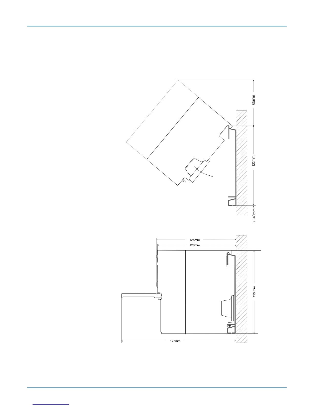
2.2 Installation dimensions
n1tier width (WxHxD) in mm: 40 x 125 x 120
n1tier width (WxHxD) in mm: 80 x 125 x 120
n1tier width (WxHxD) in mm: 120 x 125 x 120
Dimensions Basic
enclosure
Dimensions
Installation dimensions
VIPA System 300
Assembly and installation guidelines
Installation dimensions
HB130 | PS | 307-1xA00 | en | 18-01 8

2.3 Installation at the profile rail
The single modules are directly installed on a profile rail and connected via the backplane
bus connector. Before installing the modules you have to clip the backplane bus con-
nector to the module from the backside. The backplane bus connector is delivered
together with the peripheral modules.
Order number A B C
390-1AB60 160 140 10
390-1AE80 482 466 8.3
390-1AF30 530 500 15
390-1AJ30 830 800 15
390-9BC00* 2000 Drillings only left 15
*) Unit pack: 10 pieces
Measures in mm
For the communication between the modules the System 300S uses a backplane bus
connector. Backplane bus connectors are included in the delivering of the peripheral
modules and are clipped at the module from the backside before installing it to the profile
rail.
General
Profile rail
Bus connector
VIPA System 300 Assembly and installation guidelines
Installation at the profile rail
HB130 | PS | 307-1xA00 | en | 18-01 9

Please regard the allowed environment temperatures:
1 horizontal assembly: from 0 to 60°C
2 vertical assembly: from 0 to 40°C
The horizontal structure always starts at the left side with the power supply and the CPU,
then you plug-in the peripheral modules beside to the right. You may plug-in maximum 32
peripheral modules to the CPU.
If you do not deploy SPEED-Bus modules, the assembly happens with the following
approach:
1. Bolt the profile rail with the background (screw size: M6), so that you still have min-
imum 65mm space above and 40mm below the profile rail.
2. If the background is a grounded metal or device plate, please look for a low-impe-
dance connection between profile rail and background.
3. Connect the profile rail with the protected earth conductor. For this purpose there is
a bolt with M6-thread.
4. The minimum cross-section of the cable to the protected earth conductor has to be
10mm2.
5. Stick the power supply to the profile rail and pull it to the left side to the grounding
bolt of the profile rail.
6. Fix the power supply by screwing.
7. Take a backplane bus connector and click it at the CPU from the backside like
shown in the picture.
8. Stick the CPU to the profile rail right from the power supply and pull it to the power
supply.
9. Click the CPU downwards and bolt it like shown.
10. Repeat this procedure with the peripheral modules, by clicking a backplane bus
connector, stick the module right from the modules you've already fixed, click it
downwards and connect it with the backplane bus connector of the last module and
bolt it.
Assembly possibilities
Approach
VIPA System 300
Assembly and installation guidelines
Installation at the profile rail
HB130 | PS | 307-1xA00 | en | 18-01 10

CAUTION!
– Before installing or overhauling the power supplies must be discon-
nected from voltage (pull the plug or remove the fuse)!
– Installation and modifications only by properly trained personnel!
2.4 Cabling
For the cabling of power supplies gray connectors with CageClamp technology are used.
CAUTION!
– The power supplies must be released before installation and repair
tasks, i.e. before handling with the power supply or with the cabling
you must disconnect current/voltage (pull plug, at fixed connection
switch off the concerning fuse)!
– Installation and modifications only by properly trained personnel!
Overview
VIPA System 300 Assembly and installation guidelines
Cabling
HB130 | PS | 307-1xA00 | en | 18-01 11
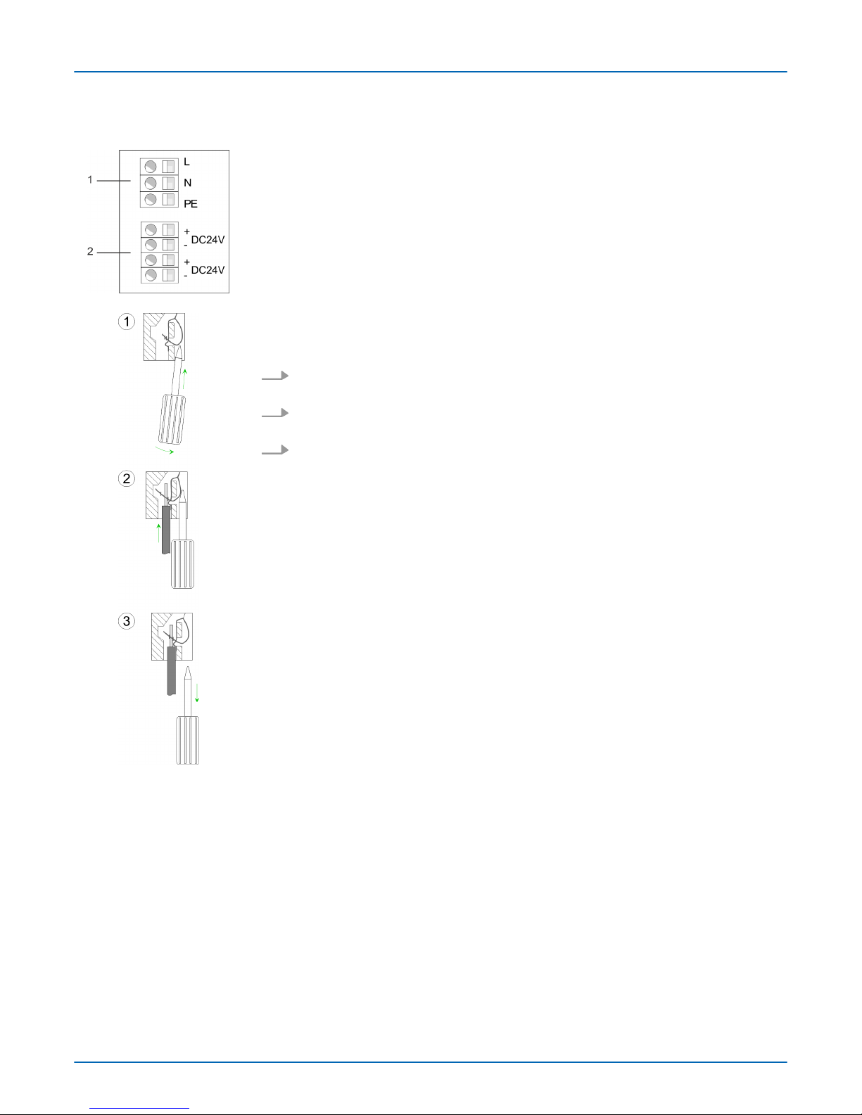
For the cabling of power supplys a green plug with CageClamp technology is deployed.
1 AC IN 100 ... 240V
2 DC OUT 24V
The picture on the left side shows the cabling step by step from top view. Here wires with
a cross-section of 0.08mm2 to 2.5mm2 may be connected. You can use flexible wires
without end case as well as stiff wires.
1. For cabling you push the locking vertical to the inside with a suiting screwdriver and
hold the screwdriver in this position.
2. To open the contact spring you have to push the screwdriver in the opposite direc-
tion and hold it. Insert the de-isolated wire into the round opening.
3. By removing the screwdriver the wire is connected safely with the plug connector
via a spring.
CageClamp technology
(gray)
VIPA System 300
Assembly and installation guidelines
Cabling
HB130 | PS | 307-1xA00 | en | 18-01 12

2.5 Installation guidelines
The installation guidelines contain information about the interference free deployment of a
PLC system. There is the description of the ways, interference may occur in your PLC,
how you can make sure the electromagnetic compatibility (EMC), and how you manage
the isolation.
Electromagnetic compatibility (EMC) means the ability of an electrical device, to function
error free in an electromagnetic environment without being interfered respectively without
interfering the environment.
The components of VIPA are developed for the deployment in industrial environments
and meets high demands on the EMC. Nevertheless you should project an EMC planning
before installing the components and take conceivable interference causes into account.
Electromagnetic interferences may interfere your control via different ways:
nElectromagnetic fields (RF coupling)
nMagnetic fields with power frequency
nBus system
nPower supply
nProtected earth conductor
Depending on the spreading medium (lead bound or lead free) and the distance to the
interference cause, interferences to your control occur by means of different coupling
mechanisms.
There are:
ngalvanic coupling
ncapacitive coupling
ninductive coupling
nradiant coupling
In the most times it is enough to take care of some elementary rules to guarantee the
EMC. Please regard the following basic rules when installing your PLC.
nTake care of a correct area-wide grounding of the inactive metal parts when installing
your components.
– Install a central connection between the ground and the protected earth conductor
system.
– Connect all inactive metal extensive and impedance-low.
– Please try not to use aluminium parts. Aluminium is easily oxidizing and is there-
fore less suitable for grounding.
nWhen cabling, take care of the correct line routing.
– Organize your cabling in line groups (high voltage, current supply, signal and data
lines).
– Always lay your high voltage lines and signal respectively data lines in separate
channels or bundles.
– Route the signal and data lines as near as possible beside ground areas (e.g.
suspension bars, metal rails, tin cabinet).
General
What does EMC mean?
Possible interference
causes
Basic rules for EMC
VIPA System 300 Assembly and installation guidelines
Installation guidelines
HB130 | PS | 307-1xA00 | en | 18-01 13

nProof the correct fixing of the lead isolation.
– Data lines must be laid isolated.
– Analog lines must be laid isolated. When transmitting signals with small ampli-
tudes the one sided laying of the isolation may be favourable.
– Lay the line isolation extensively on an isolation/protected earth conductor rail
directly after the cabinet entry and fix the isolation with cable clamps.
– Make sure that the isolation/protected earth conductor rail is connected impe-
dance-low with the cabinet.
– Use metallic or metallised plug cases for isolated data lines.
nIn special use cases you should appoint special EMC actions.
– Consider to wire all inductivities with erase links.
– Please consider luminescent lamps can influence signal lines.
nCreate a homogeneous reference potential and ground all electrical operating sup-
plies when possible.
– Please take care for the targeted employment of the grounding actions. The
grounding of the PLC serves for protection and functionality activity.
– Connect installation parts and cabinets with your PLC in star topology with the
isolation/protected earth conductor system. So you avoid ground loops.
– If there are potential differences between installation parts and cabinets, lay suffi-
ciently dimensioned potential compensation lines.
Electrical, magnetically and electromagnetic interference fields are weakened by means
of an isolation, one talks of absorption. Via the isolation rail, that is connected conductive
with the rack, interference currents are shunt via cable isolation to the ground. Here you
have to make sure, that the connection to the protected earth conductor is impedance-
low, because otherwise the interference currents may appear as interference cause.
When isolating cables you have to regard the following:
nIf possible, use only cables with isolation tangle.
nThe hiding power of the isolation should be higher than 80%.
nNormally you should always lay the isolation of cables on both sides. Only by means
of the both-sided connection of the isolation you achieve high quality interference
suppression in the higher frequency area. Only as exception you may also lay the iso-
lation one-sided. Then you only achieve the absorption of the lower frequencies. A
one-sided isolation connection may be convenient, if:
– the conduction of a potential compensating line is not possible.
– analog signals (some mV respectively µA) are transferred.
– foil isolations (static isolations) are used.
nWith data lines always use metallic or metallised plugs for serial couplings. Fix the
isolation of the data line at the plug rack. Do not lay the isolation on the PIN 1 of the
plug bar!
nAt stationary operation it is convenient to strip the insulated cable interruption free
and lay it on the isolation/protected earth conductor line.
nTo fix the isolation tangles use cable clamps out of metal. The clamps must clasp the
isolation extensively and have well contact.
nLay the isolation on an isolation rail directly after the entry of the cable in the cabinet.
Lead the isolation further on to your PLC and don't lay it on there again!
CAUTION!
Please regard at installation!
At potential differences between the grounding points, there may be a
compensation current via the isolation connected at both sides.
Remedy: Potential compensation line
Isolation of conductors
VIPA System 300
Assembly and installation guidelines
Installation guidelines
HB130 | PS | 307-1xA00 | en | 18-01 14

2.6 General data
Conformity and approval
Conformity
CE 2014/35/EU Low-voltage directive
2014/30/EU EMC directive
Approval
UL Refer to Technical data
others
RoHS 2011/65/EU Restriction of the use of certain hazardous substances in
electrical and electronic equipment
Protection of persons and device protection
Type of protection - IP20
Electrical isolation
to the field bus - electrically isolated
to the process level - electrically isolated
Insulation resistance -
Insulation voltage to reference earth
Inputs / outputs - AC / DC 50V, test voltage AC 500V
Protective measures - against short circuit
Environmental conditions to EN 61131-2
Climatic
Storage / transport EN 60068-2-14 -25…+70°C
Operation
Horizontal installation hanging EN 61131-2 0…+60°C
Horizontal installation lying EN 61131-2 0…+40°C
Vertical installation EN 61131-2 0…+40°C
Air humidity EN 60068-2-30 RH1 (without condensation, rel. humidity 10…95%)
Pollution EN 61131-2 Degree of pollution 2
Installation altitude max. - 2000m
Mechanical
Oscillation EN 60068-2-6 1g, 9Hz ... 150Hz
Shock EN 60068-2-27 15g, 11ms
VIPA System 300 Assembly and installation guidelines
General data
HB130 | PS | 307-1xA00 | en | 18-01 15

Mounting conditions
Mounting place - In the control cabinet
Mounting position - Horizontal and vertical
EMC Standard Comment
Emitted interference EN 61000-6-4 Class A (Industrial area)
Noise immunity
zone B
EN 61000-6-2 Industrial area
EN 61000-4-2 ESD
8kV at air discharge (degree of severity 3),
4kV at contact discharge (degree of severity 2)
EN 61000-4-3 HF field immunity (casing)
80MHz … 1000MHz, 10V/m, 80% AM (1kHz)
1.4GHz ... 2.0GHz, 3V/m, 80% AM (1kHz)
2GHz ... 2.7GHz, 1V/m, 80% AM (1kHz)
EN 61000-4-6 HF conducted
150kHz … 80MHz, 10V, 80% AM (1kHz)
EN 61000-4-4 Burst, degree of severity 3
EN 61000-4-5 Surge, degree of severity 3 *
*) Due to the high-energetic single pulses with Surge an appropriate external protective circuit with lightning protection
elements like conductors for lightning and overvoltage is necessary.
VIPA System 300
Assembly and installation guidelines
General data
HB130 | PS | 307-1xA00 | en | 18-01 16

3 Power supply PS 307
3.1 Safety Information
The power supplies are constructed and manufactured for:
nDC 24V supply of System 300 components.
nInstallation together with other System 300 components on one panel.
nInstallation in a cubicle with air condition.
nIndustrial usage.
Using the power supply:
nInstall the power supply together with your System 300 modules on a profile rail. In
this case the power supply has to be plugged on the outermost rim of your System
300, because otherwise the backplane bus is interrupted.
nThe power supplies are not connected to the backplane bus. When selecting the
installation position please take care that the power supply is cooled sufficiently
during operation.
In the following you will find the precautions you should take into account by using the
System 300 power supplies.
CAUTION!
– The power supplies may only be installed in dry environment where it
can only be accessed by trained personnel!
– The power supplies are not certified for explosive environments (EX-
Zone)!
– Before installing or overhauling the System 300V, the power supplies
must be disconnected from voltage (pull the plug or remove the fuse)!
– Installation and modifications only by properly trained personnel!
– Due to the compact design, the contact and fire protection to guar-
antee sufficient cooling can not be obeyed. For this reason the fire
protection has to be guaranteed by the construction of the environ-
ment of the power supply (e.g. installation in a cubicle that obeys the
fire protection rules)!
– The national rules and regulations of the respective country must be
satisfied (installation, safety, EMC ...).
Application fields
Assembly
VIPA System 300 Power supply PS 307
Safety Information
HB130 | PS | 307-1xA00 | en | 18-01 17
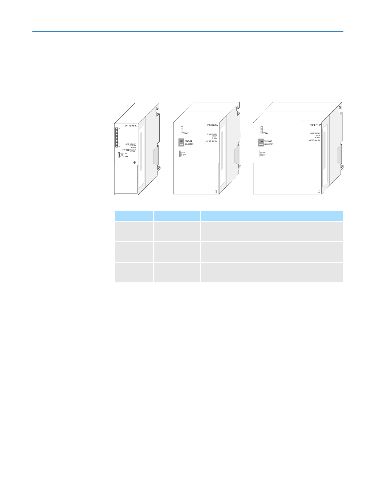
3.2 System overview
The System 300 power supplies presented here have an adjustable input voltage of
AC 120/230V and an output voltage of DC 24V. Depending on the module, the voltage is
adjusted via a 120 / 230V switch or automatically continuously from AC 100 ... 240V. For
all the inputs and outputs are on the front and the module case is isolated to the back-
plane bus, you may install the power supply together with your System 300 modules on a
profile rail.
Type Order number Description
PS 307/2.5A 307-1BA00 Power supply
primary AC 100...240V, secondary DC 24V, 2.5A
PS 307/5A 307-1EA00 Power supply
primary AC 120/230V, secondary DC 24V, 5A
PS 307/10A 307-1KA00 Power supply
primary AC 120/230V, secondary DC 24V, 10A
Power supplies
Order data
VIPA System 300
Power supply PS 307
System overview
HB130 | PS | 307-1xA00 | en | 18-01 18
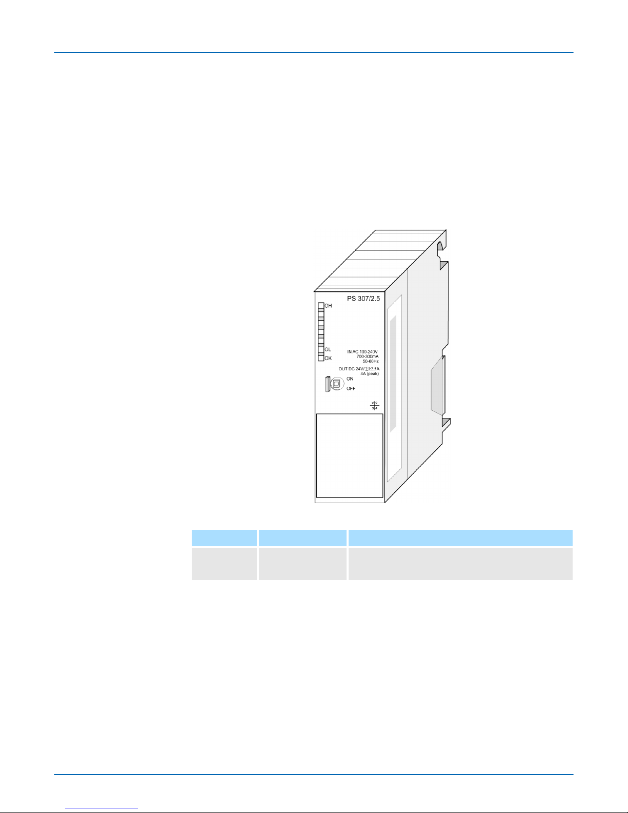
3.3 PS 307-1BA00
nOutput current 2.5A
nOutput voltage DC 24V
nConnection to single-phase AC mains Wide-range input AC 100...240V without
manual switch
nProtection against short circuits, overloads and vacancy
nUseable together with System 300 on profile rail
nSafety isolation to EN 60950
nProtection against overheat
nEfficiency typ. 90% at Inom
nMay be used as load power supply
Type Order number Description
PS 307/2.5A 307-1BA00 Power supply
primary AC 100...240V, secondary DC 24V, 2.5A
Properties
Order data
VIPA System 300 Power supply PS 307
PS 307-1BA00
HB130 | PS | 307-1xA00 | en | 18-01 19

1 Status LED
2 ON/OFF switch
The following components are beneath a flap:
3 AC IN 100 ... 240V
4 DC OUT 24V, 2.5A
CAUTION!
– The power supplies must be released before installation and repair
tasks, i.e. before handling with the power supply or with the cabling
you must disconnect current/voltage (pull plug, at fixed connection
switch off the concerning fuse)!
– Installation and modifications only by properly trained personnel!
You have to provide the power supply with alternating voltage via the input slot. A melting
fuse protects the input against overload.
To protect the main supply lines, you should install a miniature circuit-breaker of the fol-
lowing rating:
nRated current at AC 230V: 6A
nTripping characteristics: C
Structure
Circuit diagram
Input AC 100...240V
Line protection
VIPA System 300
Power supply PS 307
PS 307-1BA00
HB130 | PS | 307-1xA00 | en | 18-01 20
This manual suits for next models
2
Table of contents
Other YASKAWA Power Supply manuals


