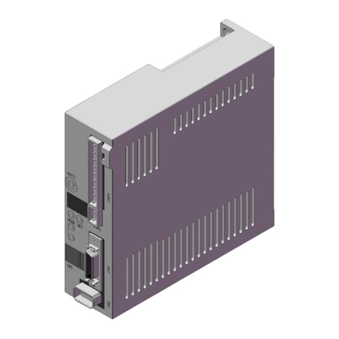
SMAC VLC-2-EIP User manual

VLC-2-EIP
USER MANUAL
Version 1.0

2
Disclaimer
The contents of this user manual are intended to be as accurate as possible, but may be subject to
change without prior notification. SMAC shall not be liable for any damages that may arise as a
consequence of the use of information presented in this user manual.
Document Version
Note
By
Date
1.0
First released version
RZ
5/13/2022
1.1
Updated the VLC-2-EIP picture and connector
numbering. Added a new section on programming
guidelines.
RZ
7/29/2022
Copyright SMAC Moving Coil Actuators, 2022.

3
Contents
Introduction .................................................................................................................................... 5
Hardware and Software Setup........................................................................................................ 7
2.1 Hardware................................................................................................................................. 7
2.1.1 Power/signal/communication connectors...................................................................... 7
2.1.2 I/O electrical schematics ............................................................................................... 13
2.1.3 LEDs ............................................................................................................................... 15
2.1.4 Optional: disabling the STO........................................................................................... 16
2.2 Software ................................................................................................................................ 17
2.2.1 VLC configuration .......................................................................................................... 17
2.2.2 Modification of IP settings ............................................................................................ 17
2.2.3 Connecting VLC-2-EIP to an Ethernet/IP network (with a Studio 5000 example) ........ 18
Programming the VLC-2-EIP.......................................................................................................... 22
3.1 Servo objects......................................................................................................................... 22
3.1.1 Acyclic servo objects...................................................................................................... 22
3.1.2 Cyclic servo objects ....................................................................................................... 25
3.2 Executing motion through servo objects .............................................................................. 28
3.3 VLC-2-EIP Programming Guidelines ...................................................................................... 29
3.3.1 General guidelines......................................................................................................... 29
3.3.2 Phasing/Homing management...................................................................................... 29
3.3.3 Fault management ........................................................................................................ 30
3.4 Controlling the VLC-2-EIP with a PLC using Studio 5000 software utilizing Add-On-
Instructions........................................................................................................................................ 31
3.4.1 Basic servo configuration .............................................................................................. 31
3.4.2 Input and status display ................................................................................................ 34
3.4.3 Digital I/O....................................................................................................................... 35
3.4.4 Fault management ........................................................................................................ 36
3.4.5 Phasing .......................................................................................................................... 37
3.4.6 Homing .......................................................................................................................... 39
3.4.7 Position Move................................................................................................................ 41
3.4.8 Velocity Move................................................................................................................ 44
3.4.9 Torque Move................................................................................................................. 46
3.4.10 Current Move ................................................................................................................ 48
3.4.11 Softland ......................................................................................................................... 49

4
3.4.12 Stop Motion................................................................................................................... 51
3.4.13 Motor OFF and ON ........................................................................................................ 52
A Appendix A: VLC System Macros................................................................................................... 53

5
Introduction
The VLC-2-EIP is an ODVA-conformant Ethernet/IP servo drive that is based on SMAC’s VLC-25-07 2-
axis integrated controller/driver and an additional layer that provides the Ethernet/IP connectivity. As
opposed to the traditional daisy-chaining of two separate Ethernet/IP servo drives for the control of
2-axis system such as SMAC’s LCR/LAR series actuators, a single VLC-2-EIP is able to achieve the same
task at a lower cost and a lower installation complexity.
The VLC part of the servo drive is pre-programmed with system macros to accommodate control and
monitoring functionalities of the servo drive. Additional macros can be programmed in the VLC to
perform subroutines/functions that can be called from the Ethernet/IP master. Background knowledge
on the VLC is required to configure the servo parameters of the VLC-2-EIP. Please refer to the latest
VLC-25-07 manual for more information on the servo drive parameters and programming.
Table 1.1. VLC-EIP-25 specifications (based on Hardware version 1.0).
Description
Ethernet/IP 2-axis servo motor controller/driver
Operating Modes
Position, Velocity, Torque
Filter Algorithm
PID
Max. Servo Loop Rate
100 µS
Trajectory Generator
Trapezoidal, electronic gearing
Servo Position Feedback
Incremental Encoder with Index
Output
PWM (space-vector-modulated), 6.0 A Continuous and 7.8 A
Peak.
Motor Type
3-Phase Brushless, DC Brushed, DC Linear Actuator
PWM Frequency
20.0 KHz
Current resolution
2.93 mA (approximate)
Encoder and Index Input
Differential
Encoder Supply Voltage
5 VDC
Encoder Input Voltage
5.5 VDC Max., -0.1 VDC Min.
Encoder Count Rate
40 million encoder counts per second
Position Range
31 Bits
Velocity Range
31 Bits
Acceleration Range
31 Bits
General Purpose Digital I/O
4x opto-isolated digital inputs, 5V to 24 V max
4x opto-isolated digital outputs, 60V, 200 mA max
Dedicated Digital I/O
2x opto-isolated coarse home inputs
STO (Safe Torque Off)
2x STO opto-isolated digital inputs, 5V to 24 V max
1x STO opto-isolated feedback output, 60V, 200 mA max
Analog Inputs
2x 12-bit pseudo-differential analog inputs, 0 to +/- 10V range
3x 12-bit analog inputs, 0V to 10V range (0V to <10V optional)
Analog Outputs
2x 12-bit analog outputs, 0V to 10V range (0V to 5V optional)

6
LEDs
1x Power on LED
1x Status LED
2x Fault LEDs
Serial Interface
RS-232 non-isolated, 9600 baud default, selectable between
2400 - 921600
Supply Voltage
+8 To +48 VDC
Protections
> Reversed power supply polarity connection
> Driver overtemperature
> I2T
> (excessive) servo position error
Program space (VLC part)
> Macro storage: 56286 bytes
> Maximum number of macros: 512
> Maximum number of program registers: 2048

7
Hardware and Software Setup
2.1 Hardware
2.1.1 Power/signal/communication connectors
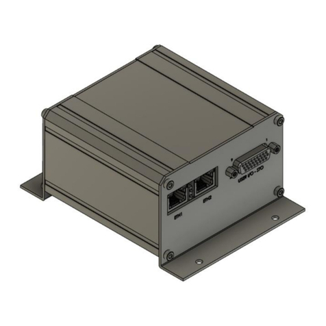
Figure 2.1 shows the VLC-2-EIP, consisting of a mother- and daughter- boards. The motherboard is
essentially a VLC-25-07 (2-axis integrated controller/servo drive), whereas the daughterboard
contains all the Ethernet/IP-related components. Pinout details of the connectors J1-J8, ETH1-2 and
status LEDs in Fig. 2.1 are presented in the following pages.
Figure 2.1. VLC-2-EIP
J1
J2
J4
J6
J8
Status LEDs
J7
J5
J3
ETH1
ETH2

8
J1 - Power interface
2 pin terminal block header, 5.08 mm pitch.
Pin number
Signal
Description
1
V+
Power supply positive
2
V-
Power supply return / ground
J2 –General purpose + dedicated digital opto-isolated I/O
D-SUB 15 connector, high-density, male.
Pin number
Signal
Description
1
GPI0
General purpose digital input 0
2
GPI1
General purpose digital input 1
3
GPI2
General purpose digital input 2
4
GPI3
General purpose digital input 3
5
GPI_COM
Common terminal for general purpose digital inputs
6
GPO0
General purpose digital output 0
7
GPO1
General purpose digital output 1
8
GPO2
General purpose digital output 2
9
GPO3
General purpose digital output 3
10
GPO_COM
Common terminal for general purpose digital outputs
11
+5V
+5V power for external circuitry
12
STO2
STO input 2
13
STO1
STO input 1
14
STO_FB
STO feedback output
15
STO_COM
Common terminal for STO’s
1
2

9
J3 –Axis 2 Motor Output
4 pin terminal block header, 5.08 mm pitch.
Pin number
Signal
Description
1
2MA
Axis 2 motor phase A/U (positive for single-phase actuators)
2
2MB
Axis 2 motor phase B/V (negative for single-phase actuators)
3
2MC
Axis 2 motor phase C/W
4
GND
Ground
J4 –Analog I/O
D-SUB 15 connector, high-density, female.
Pin number
Signal
Description
1
AN_IN2
Analog input 2, single-ended
2
AN_OUT0
Analog output 0
3
AN_OUT1
Analog output 1
4
AN_IN0+
Analog input 0, differential input +
5
AN_IN1+
Analog input 1, differential input +
6
AN_IN3
Analog input 3, single-ended
7
GND
Ground
8
GND
Ground
9
AN_IN0-
Analog input 0, differential input -
10
AN_IN1-
Analog input 1, differential input -
11
AN_IN4
Analog input 4, single-ended
12
+5V
+5V power for external circuitry
13
+5V
+5V power for external circuitry
14
GND
Ground
15
GND
Ground
1
2
3
4
1
6
5
10
11
15

10
J5 –Axis 1 Motor Output
4 pin terminal block header, 5.08 mm pitch.
Pin number
Signal
Description
1
1MA
Axis 1 motor phase A/U (positive for single-phase actuators)
2
1MB
Axis 1 motor phase B/V (negative for single-phase actuators)
3
1MC
Axis 1 motor phase C/W
4
GND
Ground
J6 –Communication (RS232)
D-SUB 9 connector, female.
Pin number
Signal
Description
1
+5V
+5V power for external circuitry
2
TX
RS232 Transmit
3
RX
RS232 Receive
4
N/C
Not connected
5
GND
Ground
6
N/A
Reserved, do not connect
7
N/A
Reserved, do not connect
8
N/A
Reserved, do not connect
9
N/A
Reserved, do not connect
1
2
3
4
1
6
5
9

11
J7 –Incremental encoder interface
D-SUB 26 connector, high-density, female.
Pin number
Signal
Description
1
N/C
Not connected
2
N/C
Not connected
3
N/C
Not connected
4
+5V
+5V power for external circuitry
5
+5V
+5V power for external circuitry
6
2A-
Axis 2 encoder phase A-
7
2A+
Axis 2 encoder phase A+
8
1A-
Axis 1 encoder phase A-
9
1A+
Axis 1 encoder phase A+
10
N/C
Not connected
11
N/C
Not connected
12
1HOM
Axis 1 home input
13
GND
Ground
14
GND
Ground
15
2B-
Axis 2 encoder phase B-
16
2B+
Axis 2 encoder phase B+
17
1B-
Axis 1 encoder phase B-
18
1B+
Axis 1 encoder phase B+
19
2HOM
Axis 2 home input
20
N/C
Not connected
21
GND
Ground
22
GND
Ground
23
2Z-
Axis 2 encoder phase index-
24
2Z+
Axis 2 encoder phase index+
25
1Z-
Axis 1 encoder phase index-
26
1Z+
Axis 1 encoder phase indx+
1
6
5
9

12
J8 –Expansion I/O
RJ-25 socket connector.
Pin number
Signal
Description
1
RX-
Receive data- input
2
TX-
Transmit data- input
3
RX+
Receive data+ input
4
TX+
Transmit data+ input
5
CLK+
Clock+ input
6
CLK-
Clock- input
ETH1 & ETH2 (Ethernet/IP ports)
RJ-45 Jack.
Pin
Signal
Description
1
TD+
Transmit data +
2
TD-
Transmit data -
3
RD+
Receive data +
6
RD-
Receive data -
1
6
1
8

13
2.1.2 I/O electrical schematics
Digital inputs
Digital outputs
+5 V
GPI_COM
GPI1
To μC
To μC
To μC
10KΩ
10KΩ
10KΩ
(5 –24 VDC)
(5 –24 VDC)
(5–24 VDC)
(5 –24 VDC)
To μC
10KΩ
GPI2
GPI4
GPI3
Internal to VLC-2-EIP
Optocouplers
GPO1
GPO_COM
(200 mA, 60 VDC tolerant)
Sinking output from
μC output circuitry
620Ω
GPO2
GPO3
GPO4
620Ω
620Ω
620Ω
Sinking output from
μC output circuitry
Sinking output from
μC output circuitry
Sinking output from
μC output circuitry
+5 V
(200 mA, 60 VDC tolerant)
(200 mA, 60 VDC tolerant)
(200 mA, 60 VDC tolerant)
(200 mA, 60 VDC tolerant)
Internal to VLC-2-EIP
Solid-state relays

14
Home inputs
STO
Analog input (differential)
+5 V
1HOM
To μC
4.7KΩ
To μC
2HOM
Internal to VLC-2-EIP
Optocouplers
4.7KΩ
+5 V
STO1
STO2
STO_FB
2.5 kΩ
To μC
+5 V
(5 –30VDC)
(200 mA, 60 VDC tolerant)
Internal to VLC-2-EIP
Solid-state relay
(5 –30VDC)
Opto
-couplers
AND gate
STO_COM
To μC
2.5 kΩ
330 Ω
To driver
power supply
AN_INx+
0 –3.0 VDC
To μ
C ADC
(12-bit)
Internal to VLC-2-EIP
Differential amplifier
AN_INx-
(-10 VDC to 10 VDC)
x = 1,2

15
Analog input (single-ended)
Analog output
2.1.3 LEDs
Figure 2.2. VLC-2-EIP status LED’s.
There are 4 LEDs in VLC-2-EIP, namely power, status, axis 1 fault and axis 2 fault. The location of
these LEDs can be seen in Figure 2.2.
•Power LED turns ON when the specified DC voltage is supplied into the controller
•Status LED blinks if an incorrect program command is executed
•Axis fault LED turns ON when the corresponding servo axis experiences fault such as driver
overtemperature, I2T trip and excessive servo position error (SE command).
(0 –10VDC)
AN_INx
40.612 kΩ
20 kΩ
To μC ADC
(12-bit)
1 nF
Internal to VLC-2-EIP
From μC DAC (12-bit)
Internal to VLC-2-EIP
(0 - 10 VDC)
Non-inverting amplifier
AN_OUTx
x = 1,2
POWER
STATUS
FAULT 1
FAULT 2

16
2.1.4 Optional: disabling the STO
The two STO inputs (STO1 and STO2, see section 2.1.2) have to be supplied with the specified DC
voltage in order to enable the VLC’s driver power stage to operate the actuator. If the external means
of supplying the DC voltage is not considered, the VLC’s on-board +5V supply can be used to supply
STO1 and STO2, and together with connecting the STO_COM with the GND, the power stage is enabled.
This is shown in Figure 2.3. When both STO1 and STO2 are energized, the STO_FB output becomes
active to indicate the drive is ready to be operated.
Figure 2.3. Disabling STO in VLC-2-EIP with the on-board +5V supply.
1
6
5
10
11
15
J2
J4

17
2.2 Software
2.2.1 VLC configuration
Remark: to perform VLC configuration, the user is expected to be familiar with programming
the VLC/LAC. Refer to the latest VLC-25-07 manual for more information on the programming.
Serial communication can be established between the VLC part and a PC through the RS232
port (J6) of the VLC-EIP-25. A serial terminal software (with selectable baud rates of up to
921600, such as Tera Term) can be used to configure the VLC for the following purposes:
•Loading of system macros (unless the macros were pre-loaded in the VLC)
•Setting/tuning of actuator servo parameters (Optional, this can also be done through
Ethernet/IP)
•Programming of custom macros to be called via Ethernet/IP (Optional)
Appendix A presents the system macros. Due to these macros, there are restrictions in
programming the custom macros as follow:
•All macros can be used except the reserved: 0 –3, 120 –162, 300 –326, 400 –439
•All registers can be used except: 200-413
For the VLC configuration, follow these steps:
•Set the serial baud rate of the serial terminal software to 921600.
•Type in the command EN and press enter. Note that any commands will not show up
in the terminal window, unless this step has been performed.
•Set the VLC baud rate to a lower value, e.g. 9600, through the command BR9600 and
press enter.
•Set the serial baud rate of the terminal software to 9600.
•At this point, the VLC can be configured/programmed as it is typically done.
2.2.2 Modification of IP settings
Table 2.1 presents the default values of the IP settings of the VLC-2-EIP. These settings can be
modified through Ethernet/IP explicit message set attribute service of the standard TCP/IP
object (Class 0xF5), instance 1, attribute 5 (Interface Configuration). The VLC-2-EIP will take the
newly modified IP settings after a power cycle.
Table 2.1. IP-settings-related objects of VLC-2-EIP
Name
Type
Default Value
IP address
UINT32
0xC0A80069 (192.168.0.105)
Network Mask
UINT32
0xFFFFFF00 (255.255.255.0)
Gateway Address
UINT32
0.0.0.0
Name Server
UINT32
0
Name Server 2
UINT32
0

18
Users could use a free Ethernet/IP explicit messaging software such as Molex EIPTool to perform
the IP settings modification. The steps are as follow:
•Set the PC’s IP address to 192.168.0.1
•Open the Molex EIPTool software.
•Refer to the figure below and perform the following
oSet the station to: 192.168.0.105
oSet the Communications to either UCMM or Connected. Select the 0xF5 TCP/IP
tab.
oClick on Get_Attribute of the Interface Configuration (attr 5). This will show the
default IP settings of Table 2.1.
oChange the parameters of the Interface Configuration (attr 5) as required and
click on Set_Attribute.
oThe newly set parameters (IP settings) will be applied after power cycling the
VLC-1-EIP.
2.2.3 Connecting VLC-2-EIP to an Ethernet/IP network (with a Studio 5000 example)
The VLC-2-EIP is ready to be connected to an Ethernet/IP network, provided the following
conditions are met
•System macros have been loaded and saved in the VLC
•The RS232 cable is disconnected from the RS232 port (J6) and after that, the VLC-EIP-
25 is power-cycled.

19
2.2.3.1 Installation of EDS file
the EDS (Electronic Data Sheets) file of the VLC-2-EIP can be obtained from SMAC. In the Studio
5000 environment, create a new project. The EDS file installation steps are as follow (refer to
Fig. 2.4):
1. Go to Tools>EDS Hardware Installation Tool
2. Click Next
3. Select “Register an EDS file”
4. Select “Register a single file” and use “Browse” to find the EDS file
5. Click “Finish” to complete the setup
Figure 2.4. Installation of EDS file in Studio 5000.
1
2
3
4
5

20
2.2.3.2 Adding the VLC-2-EIP into the PLCs Ethernet/IP network
1. In the left-pane of Studio 5000 environment, right-click on ‘Ethernet’ and select ‘New Module..’
2. Search for the device’s name corresponding to the EDS file, as shown below, e.g. ‘VLC-EIP-25’.
Double-click on the one corresponding to the VLC-2-EIP. In the ‘New Module’ window, specify
a name for the VLC-EIP and the IP address based on the discussion in section 2.2.2 of this
manual, whether the default one or a newly-defined one is used.
Table of contents
Other SMAC Servo Drive manuals
Popular Servo Drive manuals by other brands
Allen-Bradley
Allen-Bradley MPL-A310, MPL-A320, MPL-A330, MPL-A420, MPL-A430, MPL-A4530,MPL-A4540, MPL-A4560, MPL-A520, MPL-A540, MPL-A560, MPL-B310,... installation instructions
VERVIEW
VERVIEW Atlas OVU00247 quick start guide
SSD Drives
SSD Drives 637 product manual
Sinee
Sinee EA180 Series manual
JUNG ANTRIEBSTECHNIK U. AUTOMATION GMBH
JUNG ANTRIEBSTECHNIK U. AUTOMATION GMBH HighDynamic HA01-23 installation guide
INVT
INVT SV-DA200 Series Operation manual
