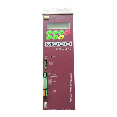
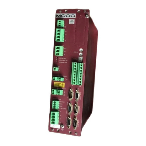
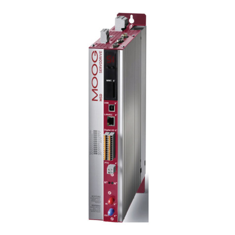
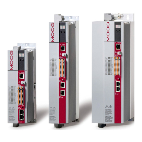
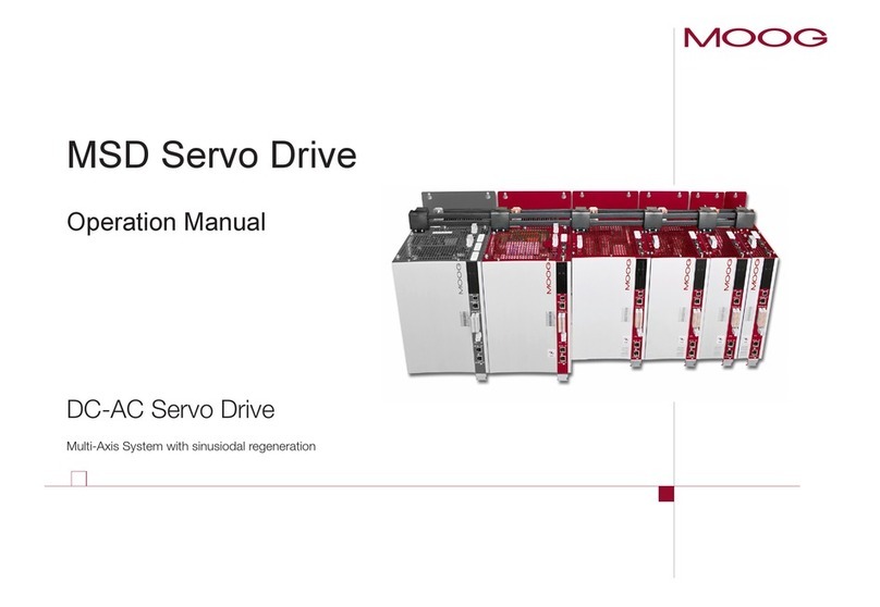
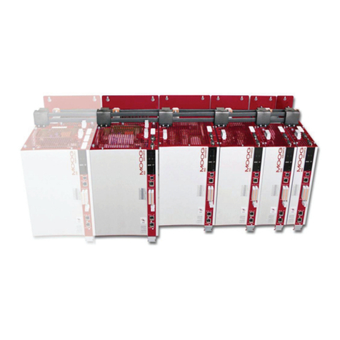
Moog DR2020 Series User manual

4
6
INDICE
4
4
4
5
5
6
6
7
11
12
13
14
15
15
16
17
18
19
20
20
1. OVERVIEW
1.1. Contents
1.2. Utilized symbols
1.3. Packaging contents
1.4. Qualifications of recipients
1.5. Standards of reference
2. DESCRIPTION OF THE SYSTEM
2.1. Product structure
2.1.1. Product description
2.1.2. Operating and storage conditions
2.1.3. Standard power supply unit models
2.1.4. Power supply unit coding
2.1.5. Standard axis modules
2.1.6 Axis module coding
2.1.7. Capacitor modules models and coding (ABC Auxiliary Bus Capacitor)
2.2. Characteristics and components details
2.2.1. Power supply unit electrical data
2.2.2. Power supply unit mechanical data
2.2.3. Connectors
2.2.3.1. Connectors Layout
2.2.4. Filters
2.2.5. Brake resistors
2.2.6. Line inductors
2.2.7. Cables
2.2.8. Capacitor module (ABC)
2.3. Axis Module
2.3.1. General description of functions
2.3.2. Mechanical dimensions
2.3.3. Position transducers
2.3.4. Interfaces with “field” and other modules
21
23
24
25
25
26
26
10
MAR2-E-191
DR2020
USE AND MAINTENANCE MANUAL
DECENTRALIZED DIGITAL SERVO DRIVE
m

27
30
33
27
27
27
27
28
28
28
28
28
28
29
29
29
29
29
30
31
33
33
33
33
33
33
33
33
34
34
35
35
35
36
36
36
36
37
38
38
2.4. Safety and Usage Instructions
2.4.1.
General safety Description
2.4.2.
STO Safety Function
2.4.2.1.
Description
2.4.2.2.
Safety instructions
2.4.3. Instructions for drive usage
2.4.3.1. Directed use
2.4.3.2.
Distribution board and wiring
2.4.3.3. Power supply
2.4.3.4. Motors
2.4.3.5. Prohibited use
2.4.3.6. In house storage duration
2.4.3.7. Maintenance/cleaning
2.4.3.8. Decommissioning
2.4.3.9. Repair
2.4.3.10 Disposal
3. TYPE APPROVALS
3.1. EC
3.2. Safety and Safe Torque Off (Block on restart)
4.ELECTRICAL AND MECHANICAL INSTALLATION
4.1.
Tools and instruments
4.2. Mechanical installation
4.2.1. Assembling the components
4.2.1.1. Assembling the power supply unit
4.2.1.2. Assembling the axes
4.2.1.3. Assembling the filters
4.2.1.4. Assembling the inductors
4.2.1.5. Brake resistor positioning
4.3. Electrical installation and thermal sizing
4.3.1. Safety and general instructions
4.3.2. Thermal sizing of the board
4.3.2.1. Dissipation of the power supply unit
4.3.2.2. Dissipation of the axes
4.3.2.3. Thermal dissipation of the accessories
4.3.3. Auxiliary power supply characteristics
4.3.4. Connection to the mains
4.3.4.1. Types of mains network
4.3.4.2. Protection components
4.3.4.3. Earth connection
4.3.5. Power supply unit wiring
1
DR2020
MAR2-E-191
1

45
38
38
38
39
39
39
39
40
41
41
42
43
45
46
46
46
47
48
49
51
51
52
52
52
53
53
54
55
55
55
55
56
58
59
60
61
64
64
65
66
4.3.5.1.
Earthing
4.3.5.2.
Power cable connection
4.3.5.3.
Brake resistorconnector
4.3.5.4.
BUS BAR connection
4.3.5.5.
Auxiliary power connection
4.3.6.
Axis module wiring
4.3.6.1.
Earthing
4.3.6.2.
Motor cable connection
4.3.6.3.
Motor brake cable connection
4.3.6.4.
STO signal connectors
4.3.6.5.
Trasducers connection
4.3.6.6.
Connecting Filedbus - connectors X8, X9, X10
5. COMMISIONING USING THE GUI
5.1. Safety
5.2. Dx2020 GUI
5.2.1. General description
5.2.2. Minimum PC requirements
5.2.3 Dx2020GUI Installation
5.2.4 Connection GUI-drive
5.2.5. Layout
5.2.6. Firmware Update (BootLoader)
5.2.7. How to access the Online Help
5.3. System Configuration
5.3.1. Axis module identification
5.3.2. Motor Parameters Configuration
5.3.3. Transducers Configuration
5.3.3.1. Sensorless
5.3.4. I/O Configuration
5.3.5. Control Loops Configuration
5.3.5.1 Control Mode Configuration
5.3.5.2. Torque Loops Parameters Configuration
5.3.5.3. Speed Loops Parameters Configuration
5.3.5.3.1 Filter configuration
5.3.5.4. Position Loops Parameters Configuration
5.3.6. Fault configuration
5.3.7. Application parameters
5.3.8. Configuration of modes and commands
5.4. Power supply
5.5. Enabling the STO
5.5.1 Autophasing
5.6 . Enabling the Axis
5.7. Oscilloscope function and log files (*.UCX) 67
DR2020
MAR2-E-191
2

72
67
67
68
69
70
71
72
72
72
73
73
73
74
74
74
74
75
76
76
76
77
77
78
81
82
82
82
83
83
83
84
84
85
87
89
89
89
90
90
5.7.1.
Configure recording
5.7.2.
Launch recording
5.7.3.
View the record
5.7.4.
UCX file management
5.8.
Use of the GUI in OFF LINE mode
5.9.
Parameter management menu
6. TROUBLESHOOTING
6.1. Introduction
6.2. Power supply unit anomalies
6.3. Axis module anomalies
6.3.1. Power section Alarms
6.3.2. Alarm due to VBUS voltage not within tolerance limits
6.3.3. Drive or motor overtemperature
6.3.4. STO signal removal
6.3.5. Memory device errors
6.3.6. Data Corrupted Fault
6.3.7. Brake Chopper Fault
6.3.8. Feedback device errors
6.3.9. Synchronization, Interrupt Time and Task Time Error
6.3.10. EtherCAT Faults
6.3.11. Internal Communication Fault
6.3.12. Control loop Alarms
6.3.13. CAN Bus Alarms
6.4. Alarms Identification
6.5. Anomalies during GUI-Drive connection
7. SAFE TORQUE OFF SAFETY FUNCTION
7.1.
Application
7.2.
Risk assessment of the installation
7.3.
Safe Torque Off function
7.3.1.
Characteristic values according to
UNI EN ISO 13849-1
7.3.2.
Characteristic values according to
CEI EN 62061
7.4.
Safety requirements
7.5.
Safe Torque Off Circuit
7.6.
Safe Torque Off Connections
7.7.
Application example
7.8.
Safe Torque Off installation and and maintenance procedure
7.9.
Assembly and production tests
7.10.
Identification of Safe Torque Off function on the drive plate
8 Annexes
8.1.
Glossary
8.2.
Metric/AWG cinversion table 93
DR2020
MAR2-E-191
3

1. OVERVIEW
Contents
This manual provides information on the correct installation and optimal operation of the DR2020 series of digital multi-axis
servo drives.
All information in this manual, including methods, technologies and concepts is the exclusive property of Moog-Casella, and may
not be copied or reused without specific authorisation.
Moog-Casella reserves the right to make changes to the product and relative documentation, at any time, without notice.
The following documents are available on the Website:
•QUICK GUIDE - INSTRUCTIONS AND GUIDELINES FOR INITIAL START-UP
•USER AND INSTALLATION MANUAL (this document)
•FIELDBUS MANUAL
•CONFIGURATION SOFTWARE Dx2020 GUI
WARNING
When the drive is operating, there is a risk of death, serious injury or serious material damage.
The installer shall therefore make sure that the safety instructions in this manual are read, understood
and observed by all personnel responsible for operating the drive.
AVERTISSEMENT
Lorsque l'entrainement est en marche, il existe un risque de mort, blessures graves ou dommages
matériels importants. L'installateur doit donc veiller à ce que les consignes de sécurité dans ce manuel
sont lues, comprises et respectées par tout les le personnel responsable de commander l'entraînement.
1.2.
S
ymbols used
WARNING: Hazard that may result in death or serious injury
Hazard that may result in minor injury and/or material damage
Important information
1.3. Contents
A DR2020 includes:
•
A DR2020 module
Note: a connectors' kit (see page 6) or a connection cable between DR2020 modules, must be ordered
separately, specifying the needed length.
DR2020
MAR2-E-191
4

1.4. Qualifications of recipients
This manual is intended for qualified personnel, i.e. with the following skills, depending on their functions:
Transport: personnel shall have knowledge of handling electrostatically sensitive components
Unpacking: personnel shall have knowledge of handling electrostatically sensitive components that are sensitive to impact
Installation: personnel shall have knowledge of installing electrical equipment
Start-up: personnel shall have extensive technical knowledge of electrical drive technology.
INFORMATION
Qualified personnel shall be familiar with and observe the following standards:
IEC 60364, IEC 60664 and national accident prevention regulations.
WARNING
When the drive is operating, there is a risk of death, serious injury or serious material damage.
The installer shall therefore make sure that the safety instructions in this manual are read, understood
and observed by all personnel responsible for operating the drive.
AVERTISSEMENT
Lorsque l'entrainement est en marche, il existe un risque de mort, blessures graves ou dommages
matériels importants.
L'installateur doit donc veiller à ce que les consignes de sécurité dans ce manuel sont lues, comprises et
respectées par tout le personnel responsable de commander l'entraînement.
1.5. Reference standards
The DR2020 drives conform to the Low Voltage Directive (2014/35/EC) and EMC Directive (2014/30/EC).
The “Safe Torque Off” (STO) safety function built into the drive conforms to the Machinery Directive (2006/42/EC).
To conform to European Directives, the product meets the requirements of the relevant harmonised installation standards
EN61800-5-1 (LVD), EN61800-3 (EMC) and EN 61800-5-2 (Safety of machinery), EN60034-1, EN60034-5 (Electric Rotary
Machines).
The DR2020 drives are CE certified.
DR2020
MAR2-E-191
5

2. DESCRIPTION OF THE SYSTEM
2.1. Product structure
2.1.1.
Product description
The DR2020 drive is the new generation of digital servo drives manufatured by Moog-Casella for controlling brushless
synchronous or asynchronous motors. It's a decentralized servo drive that can be positioned directly on the machinery with a DC power
supply module.
•The power supply of the DM2020 supplies the "power" in direct current (+ AT and -AT) to the different DR2020 through the
connection cable applied on the terminal board
•The first two upper connectors of the power supply terminal board carry the auxiliary power supply + 24Vdc
•The second two connectors at the bottom carry the power supply +/- AT (ATTENTION HIGH VOLTAGE 560VDC or higher)
•There are two standard power supply models (those of the DM2020 multi-axis drive)
•Each DR2020 axis module is only available in the single axis version
•The current flows of the various DR2020 axes range from 2 Arms to 8 Continuous Arms and 4 Arms to 16 Peak Arms
•Sizes are 4
•The control modes are 3
ModeNote
Analog input Opzional (*)
Can Bus Fieldbus Opzional (*)
EtherCat Fieldbus Standard version
(*) under development
•The DR2020 is equipped with the circuit for controlling a stationary brake integrated in the motor.
Size Rated Current
Arms Peak Current
Arms
2/4 2,0 4.0
4/8 4,0 8.0
6/15 6,0 12.0
8/16 8,0 16,0
•Compatable feedback devices (to be specified on the order)
−Serial RESOLVER
−USB RESOLVER
−Sincos Serial ENCODER
−Sincos USB ENCODER
DR2020
MAR2-E-191
6

2.1.2.
Operating and storage conditions
Ambient operating
temperature
from 0 °C to 40 °C
Storage temperature from -25 °C to 55 °C
Transport temperature from -25 °C to 70 °C
Humidity permitted
during operation
5…95 %
condensation not allowed
Humidity permitted
for storage 5…95 %
Humidity permitted for transport
transportnsport 95 % a 40 °C
Operating height Up to 1000 m above AMSL, over 1000 m above AMSL with reduced
current (-2%/100 m) max. 2000 m above AMSL
Certification CE, UL (pending)
IP Protection rating IP65
Tab 2.1 Environmental conditions
•The modules can be cooled by natural convention or by a radiating back surface
•Ethernet interface on which the EtherCAT Real Time protocol is implemented with the DS402 profile (standard)
•Standard CANOpen interface (under development) on which the CANOpen protocol is implemented with the DS402
profile
•“Safe Torque Off” (STO) (protection against accidental start-up) incorporated into each DR2020 module
•Configuration/commissioning via GUI: Dx2020GUI, with USB interface (X6 connector), located at the side of the
Fieldbus connectors allows users to configure, calibrate and control the drive
•Alarm diagnostics: Via GUI or Field Bus
•Accessories:
oEMC filters (supplied with the power supply)
oPower and signal cables
oBrake resistor (supplied with the power supply)
Note: High voltage power can be obtained from the DM2020 Power Supply.
Mechanical resistance in
compliance with EN 60721-3-3
CLASS 3M7
Vibration: stat/sinusoidal:
•10mm for frequences between 2…9
•30 m/s2 for non-stationary vibration
Non-stationary vibration and Type II impacts:
•250 m/s2 (25 g) for 6
ms
Machine Safety STO (Safe Torque Off) SILCL 3 PL “e” (pending)
DR2020
MAR2-E-191
7

Drive Dimensions
DR2020
MAR2-E-191
8

BR8904-R
BR8905-R
BR8907-R
BR8903-R
CVAMM
CVDMM
CVMMM
BR8901-R
BR8902-R
BR8900-R
Connectors and Cable coding
Connerctors' coding
X1 input connector with terminals (to the power
supply) X2 output connector (to the next DR2020
module) X3 motor connector
X4 e X5 EtherCat connectors
Connertors Kit:
it includes 4 connectors: X1, X2, X4 e X5 Cables
Coding *)
To the Power Supply
To the DR2020
To the Motor
Nota: “MM”
refers to the cables length in meters
Wire Terminal Code
X2 Connector ended for STO Feedback
Cap X5 ended for EtherCat
Cap for X2 not ended
(*) under development
BR8906-R
DR2020
MAR2-E-191
9

The power supply model code is shown on two plates: One located on the front above the protector for the module's terminal
block and the other on the right-hand side of each axis module.
To request any kind of information about a specific power supply, the details on the side plate identifying each individual
power supply must be communicated to Moog-Casella.
Nota: a 32Arms power supply module is under development
Model code
Nominal data
(A)
(B)
Serial Number
Model/Code CC201xxxxx CC202xxxxx
Mechanical dimensions 50 mm/1.97 inches 150 mm/5.9 inches
Type L50 L150
Electrical line power supply 3-phase, from 200 to 528 V AC, 50/60 Hz
Auxiliary busbar power supply 24 V DC +/- 10% (supplied externally)
Arms rated current 54 128
Arms peak current 130 256
Protection
Communication CANopen for sharing data with the drives
Cooling Incorporated ventilation
Weight (kg) 5.1 13.5
Connector code BC0004R BC0006R
Fig 2.2 Example of power supply side plate (A) and front plate (B)
DR2020
MAR2-E-191
10
NTC and bi-metallic thermal protection to 85°C
Detection of loss during input phase
Detection of insufficient input voltage or overvoltage

2.1.4. Power supply coding
Example: The code CC201A0000 identifies the standard 54 A standard power supply in the production version, with no
special variant.
Version
.Stnr Model
Eec Model
Mechanical hardware configuration
Value Length Nominal
Current (CC)
..
nc
r
nc
r
ue eron
tnr
OPT2 - Special configurations
ue eron
tnr
Hardware revision
Internal lue 2
Special Variations
ue Internal coding 2
CC
2 Values assigned by Moog
Fig 2.3 The first two characters are "CC" and refer to the family (DM2020)
-
DR2020
MAR2-E-191
11
OPT1 - Special configurations

DR2020
Model/Code CH6 52 X X X XX XX CH6 54 X X X XX XX CH6 56 X X X XX XX CH6 58 X X X XX XX
Machanical dimensions 135 L * 83 P * 222 H mm (H = 270 mm with connectors)
Configuration Single
Type L1 L2 L3 L4
Module current
@ 8 kHz 2 4 4 8
Arms rated currrent 2 4
6
8-
Arms peak current 4 8
12
16
Cooling Natural Dissipation on the plate
Weight 4.4 4.4 4.4 4.4
Connector code See p. 8
The module code is shown on the plate near the Fieldbus connectors.
To request any kind of information about a specific module, the details on the side plate identifying each individual
module must be communicated to Moog-Casella.
Nominal data
Serial Number
Model code
Fig 2.4 Example of a DR2020 axis module plate
DR2020
MAR2-E-191
12

Version
6Standard model
ESpecial model
(1) Standard Version
(2) Values assigned by Moog
Transducer type
Value Type
RRESOLVER
TUSB RESOLVER
ESerial Sincos ENCODER
USincos USB ENCODER
Value Type
0Analogue references (option)
1
2EtherCAT configuration
Hardware Revision
00Standard
Special variations
CH-
System data
Value Peak
Current
52 2 Arms
54 4 Arms
56 6 Arms
58 8 Arms
Nominal
Current Dimension
in mm
4 Arms
8 Arms
12 Arms
16 Arms
135x220x83
(1)
01OBE Special
30 SBC low level
31 SBC low level OBE Special
60 SBC high level
61 SBC high level OBE Special
135x220x83
135x220x83
135x220x83
CanBus configuration (option)
Note: Serial interface for drive setup is under development.
Value - Internal Coding
DR2020
MAR2-E-191
13
Special configurations
Fieldbus configuration

Model Code Capacity (µF) Dimension
DM2020 ABC5
CC55000
5400
50 mm (1.97 in)
DM2020 ABC4 CC55012 4500
DM2020 ABC3 CC55013 3600
DM2020 ABC2 CC55014 2700
DM2020 ABC1 CC55015 1800
Fig 2.5 Example of capacitor module side plate (A) and front plate (B))
The capacitive module can be placed alongside the power supply and the DR2020 in order to recover
kinetic energy in the braking phases; in this way, in the presence of repeated cycles of acceleration and
load braking, it is avoided to dissipate energy on the braking resistor.
Model Code
Serial Number
(A)
Nominal Data
(B)
DR2020
MAR2-E-191
14

The main function of the power supply module is to directly convert (without a transformer) mains voltage to direct voltage,
which powers the various modules that operate the servo-system motors via busbars.
Fig 2.6 Power supply block diagram (power components)
Model Type L50 (M) Type L150 (L)
ELECTRICAL DATA
Mains voltage Three-phase from 200 to 528 V AC 50/60 Hz
Auxiliary voltage 24 V DC +/-10%, 1 A (supplied externally)
Rated output current, DC BUS side 54 A 128 Arms
Peak output current, DC BUS side 130 A 256 Arms
DC-link voltage (Vout) From 282 to 744 V DC -
Protection
Communication CANopen for sharing data with the drives
Cooling Incorporated ventilation
MECHANICAL DATA
Weight 5.1 kg 13.5 kg
Height 455 mm (17.91 inches) 455 mm (17.91 inches)
Width 50 mm/1.97 inches 150 mm/5.91 inches
Depth 249 mm (9.80 inches) 249 mm (9.80 inches)
Tab 2.4 Power supply characteristics
FUNCTIONS
Soft-start circuit
Braking circuit
BUS cc voltage monitoring
Mains voltage presence and value monitoring
Power supply internal temperature monitoring
TO THE THREE-
PHASE NETWORK
R
S
T
SOFT START
RR
IGBT
CAPACITORS
PS MANAGEMENT
BUS READING
SOFT START
RR CONTROL
+AT Vbus
-AT Vbus
DR2020
MAR2-E-191
15
NTC and bi-metallic thermal protection on heat sink to 85°C
Identification of absense of input phase
Identification of insufficient voltage (undervoltage) or excessive voltage (overvoltage)

Fig 2.7 Drawing of the power supply L50
Fig 2.8 Drawing of the power supply L150
2.2.2. Power supply unit mechanical data
DR2020
MAR2-E-191
16

0 Volt
+ DC bus
- DC bus
GND
X1 Brake resistor
X2 Power connector
+24 Volt
Bus Bar
}
Status Led
CAN connectors
(Earth)
Fig 2.9 Connection layout
DR2020
MAR2-E-191
17

The tables below give details of connectors
X1: brake resistor
1+RR1
2-RR2
X2: mains
1U1
2V1
3W1
4Earth
YELLOW LED GREEN LED RED LED Status
Off Off Off Power supply off or failed
Off Off 24 Volt applied
Flashing Flashing Off Three-phase power supply present, BUS charging
Flashing Off BUS stable, axes ready to be enabled
Off Off Power supply fault
X10 LN A CAN connector (according to CIA 402 CAN on RJ45 connector)
Pin Designation Function
1Can_H CAN line positive terminal
2Can L CAN line negative terminal
30V_Ca n CAN line 0 logic
4Aux_Ps_Fault_neg Signal (denied) of power supply status
5Addr_sx_dx Address for internal communications
6Ps_out Power supply command output
7nc
8+5V_Can CAN line power supply (supplied by power supply)
2.2.3.1. Connectors layout
The tables below give details of connectors and the meaning of signalling LEDs
DR2020
MAR2-E-191
18
On, fixed light
On, fixed light
On, fixed light

X10 LN B CAN connector (according to CIA 402 CAN on RJ45 connector)
Pin Designation Function
1Can_H CAN line positive terminal
2Can L CAN line negative terminal
30V_Ca n CAN line 0 logic
4Aux_Ps_Fault_neg Signal (denied) of power supply status
5Addr_sx_dx Address for internal communications
6Ps_out Power supply command output
7nc
8+5V_Can CAN line power supply (supplied by power supply)
Filter code AT6013 (power supply M) / AT6014 (power supply L)
Rated voltage 3 x (400/480 V), 50/60 Hz, at 50 °C
Overload 1.5x per 60 s, repeatable every 60 min.
Ambient temperature From -25 °C to +100 °C, with current reduction starting from 60 °C (1.3%/°C)
Assembly height 1000 m, with current reduction of up to 4000 m (6%/1000 m)
Relative air humidity 15 - 85% (condensate not permitted)
Storage temperature From -25 °C to +70 °C
IP protection rating IP20
Acceptance test Complies with EC
Non-industrial environment -
EN61800-3
complies with radio shielding
Cable length permitted between the drive and motor up to 50 m
Industrial environment -
EN61800-3
complies with radio shielding
Cable length permitted between the drive and motor up to 100 m
Code Suitable for
power supply Type
Rated
current
[A]
Total
current
loss [W]
Current
on contact
[mA]
Weight
[kg] Connection [mm2 ]
AT6013 L50 A 1 55 26 33.4 1.8 13 mm2�ex.
PE M6 bolt
AT6014 L150 B 1 130 50 39 2.6 Up to 50 mm2
PE M10 bolt
DR2020
MAR2-E-191
19
2.2.4 Filters
If the motor power cables are shorter than 50 m, an EMC filter (code AT6013/AT6014 or equivalent can be positioned between
the network and the drive.
If cables are no longer than 50 m, we recommend contacting Moog-Casella's Application Dept.
If the application requires a direct current less than the maximun than can be managed by the power supply, filters with lower rated
curent values may be used.
Contact the Application Service for ratings and a selection of alternative models to those described above.
Table of contents
Other Moog Servo Drive manuals
Popular Servo Drive manuals by other brands
Danfoss
Danfoss 176F3166 installation instructions
Kollmorgen
Kollmorgen S20260 installation guide
Sanyo Denki
Sanyo Denki SANMOTION R3E manual
Smitec
Smitec COSMOS 301 Series Installation, use and maintenance manual
Shihlin electric
Shihlin electric SDA Series user manual
BLUM
BLUM Tandem installation instructions
Engel
Engel HBI22 Series operating manual
Fagor
Fagor ACSD series Original instructions
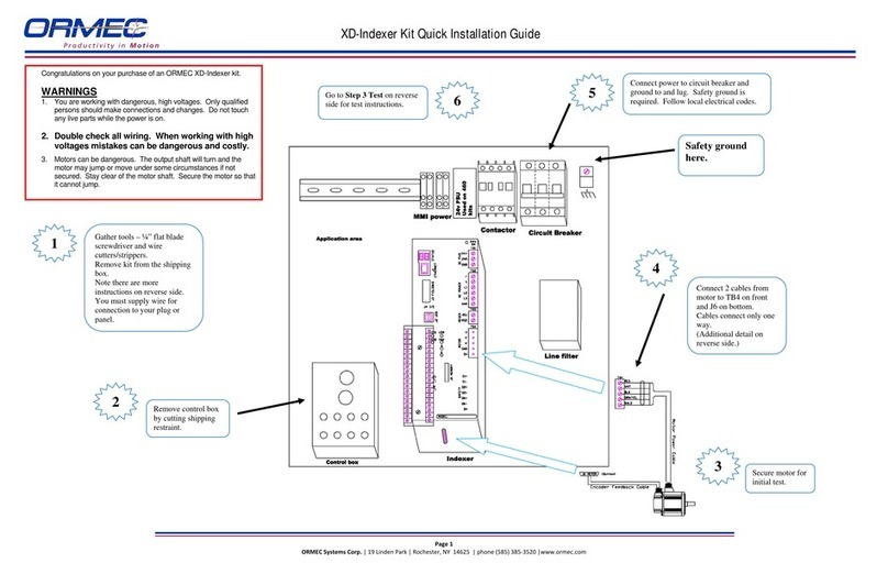
Ormec
Ormec XD-Indexer Kit Quick installation guide
Sanyo Denki
Sanyo Denki Sanmotion R instruction manual
Lenze
Lenze L-force Drives 9400 Series Mounting instructions
SSD Parvex
SSD Parvex DIGIVEX Little Drive Servoamplifier User and commissioning manual
