Yeasn YPB-2100 User manual

YPB-2100
LCD VISUAL CHART
User Manual
Version: 1.4
Revision date: 2022.12

Product Name: LCD VISUAL CHART
Nome do produto: TABELA VISUAL DE LCD
Nombre del producto: TABLA VISUAL LCD
Ürün Adı: LCD GÖRSEL ŞEMA
Nome prodotto: TABELLA VISIVA LCD
Produktname: LCD-VISUAL TABELLE
Nom du produit: TABLEAU VISUEL LCD
Име на продукта: LCD ВИЗУАЛНА КАРТА
Produkto pavadinimas: LCD ženklųekranas
Nazwa produktu: WYKRES WIZUALNY LCD
Název produktu: VIZUÁLNÍ TABULKA LCD
Toote nimi: LCD VISUAALNE KAART
Produkta nosaukums: LCD Vizuālākarte
Όνομα προϊόντος: ΟΡΑΤΙΚΟ ΔΙΑΓΡΑΜΜΑ LCD
Numele produsului: HABĂVISUALĂLCD
Productnaam: LCD VISUELE KAART
User Manual Download link: www.yeasn.com/en/
Link para download do manual do usuário: www.yeasn.com/en/
Manual de usuario Enlace de descarga: www.yeasn.com/en/
Kullanım Kılavuzu İndirme linki: www.yeasn.com/en/
Manuale d'uso Link per il download: www.yeasn.com/en/
Link zum Herunterladen des Benutzerhandbuchs: www.yeasn.com/en/
Lien de téléchargement du manuel d'utilisation: www.yeasn.com/en/
Линк за изтегляне на ръководството за потребителя: www.yeasn.com/en/
Naudotojo vadovo atsisiuntimo nuoroda: www.yeasn.com/en/
Link do pobrania instrukcji obsługi: www.yeasn.com/en/
Uživatelská příručka Odkaz ke stažení: www.yeasn.com/en/
Kasutusjuhendi allalaadimise link: www.yeasn.com/en/
Lietotāja rokasgrāmatas lejupielādes saite: www.yeasn.com/en/
Εγχειρίδιο χρήστη Σύνδεσμος λήψης: www.yeasn.com/en/
Link de descărcare manual de utilizare: www.yeasn.com/en/
Gebruikershandleiding Downloadlink: www.yeasn.com/en/

Preface
Thank you for purchasing and using our LCD visual chart.
Please read this User Manual carefully before using this device. We sincerely
hope that this User Manual will provide you with sufficient information to use the
device.
Our pursuit is to provide people with high-quality, complete-function and more
personalized devices. Information in promotional materials and packing boxes is subject
to changes due to performance improvement without additional notice. Chongqing
Yeasn Science - Technology Co., Ltd. reserves the rights to update the devices and
materials.
If you have any questions during using, please contact at our service hotline: (86-023)
62797666, we will be very happy to help you.
Your satisfaction, our impetus!
Information of manufacturer
Name: CHONGQING YEASN SCIENCE - TECHNOLOGY CO., LTD
Address: 5 DANLONG ROAD, NAN’AN DISTRICT, CHONGQING, CHINA.
Tel: 86-23 62797666

Content
1. Basic information .....................................................................................................- 1 -
1.1 Uses ................................................................................................................- 1 -
1.2 Performance Parameters.................................................................................- 1 -
1.3 Power Supply Parameters...............................................................................- 3 -
1.4 Weight and Size ..............................................................................................- 3 -
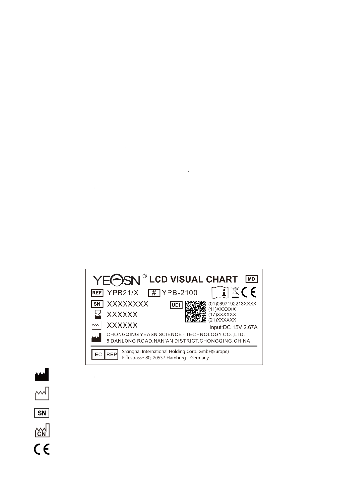
1.5 Name plate and indications ............................................................................- 3 -
2. Safety Precautions ....................................................................................................- 5 -
3. Main Structure..........................................................................................................- 8 -
3.1 Host.................................................................................................................- 8 -
3.2 Remote Controller ........................................................................................- 10 -
3.3 Power Adapter ..............................................................................................- 11 -
4 Installation ...............................................................................................................- 12 -
4.1 Part List ........................................................................................................- 12 -
4.2 Installation Instructions ................................................................................- 13 -
5. Preventive inspection..............................................................................................- 17 -
6. Directions for Use...................................................................................................- 17 -
6.1 Device Startup and Shutdown ......................................................................- 17 -
6.2 How to use the Remote Controller ...............................................................- 20 -
6.3 Other operating instructions .........................................................................- 28 -
7. Troubleshooting......................................................................................................- 29 -
8. Cleaning and Protection .........................................................................................- 30 -
8.1 Clean LCD displayer ....................................................................................- 30 -
8.2 Clean external parts ......................................................................................- 30 -
9. Maintenance ...........................................................................................................- 31 -
10. Environmental Conditions and Service Life ........................................................- 32 -
10.1 Environmental conditions for normal operation.........................................- 32 -
10.2 Environmental conditions for transportation and storage...........................- 32 -
10.3 Service life..................................................................................................- 32 -
11. Disposal and Environmental protection................................................................- 32 -
12. Manufacturer’s Responsibility .............................................................................- 33 -
13. Electrical Schematic Diagram ..............................................................................- 34 -
14. Guidance of EMC and other interference.............................................................- 35 -

- 1 -
1. Basic information
1.1 Uses
Used to detect visual sensitivity, refractive properties and binocular vision function of human eye.
Produce name: LCD visual chart.
Model: YPB-2100
Software version number: V3
Contraindications: none.
Target groups of patients: adults, children.
Intended users: optometrists in hospital ophthalmology and optical shops.
Specific qualifications of device users and/or other persons: have a qualification certificate for
optometry and glasses.
If cleaning and maintenance needed, please power off the product and unplug from the socket.
Detailed cleaning and maintenance method, please refer to 8 Cleaning and Protection 9
Maintenance.
1.2 Performance Parameters
1.2.1 LCD displayer: 23.8 inches (1920 ×1080 pixels)
1.2.2 Optometry distance: 1.5~7.3 m optional, step 0.1 m
5-24 ft optional, step 0.5 ft
1.2.3 Optotypes
Visual Chart: Used for vision test, including 6 types Charts such as “E”, “C”, Letter, Number, Kids
and ETDR.
1.2.4 Visual Charts display modes: all, single, row and column.
1.2.5 Automatic screensaver: 5 mins, 15 mins and 45 mins are optional.

- 2 -
E/C/Letter/Number/Kids
5-Grade LOG decimal1 decimal2 Imperial Metric decimal3 decimal4
3.6 1.4 0.04 0.05 20/500 20/500 0.04 0.04
3.7 1.3 0.05 0.06 20/400 20/400 0.05 0.05
3.8 1.2 0.06 0.07 20/300 20/300 0.06 0.066
3.9 1.1 0.08 0.08 20/250 20/250 0.08 0.08
4 1 0.1 0.09 20/200 20/200 0.1 0.1
4.1 0.9 0.12 0.1 20/150 20/150 0.125 0.133
4.2 0.8 0.15 0.2 20/100 20/100 0.16 0.2
4.3 0.7 0.2 0.3 20/90 20/90 0.2 0.222
4.4 0.6 0.25 0.4 20/80 20/80 0.25 0.25
4.5 0.5 0.3 0.5 20/70 20/70 0.32 0.285
4.6 0.4 0.4 0.6 20/60 20/60 0.4 0.33
4.7 0.3 0.5 0.7 20/50 20/50 0.5 0.4
4.8 0.2 0.6 0.8 20/40 20/40 0.63 0.5
4.9 0.1 0.8 0.9 20/30 20/30 0.8 0.66
5 0 1 1 20/25 20/25 1 0.8
5.1 -0.1 1.2 1.2 20/20 20/20 1.25 1
5.2 -0.2 1.5 1.5 20/15 20/15 1.6 1.33
5.3 -0.3 2 2 20/10 20/10 2 2
Remarks: When distance less than 2.5m, Chart “E”, “C”, Letter ,Number, Kids will be influenced
by pixel size, the last three lines optotypes of above chart will be shielded.
ETDRS
5-Grade LOG decimal1 decimal2 Imperial Metric decimal3 decimal4
4.5 0.5 0.3 0.3 20/63 6/20 0.32 0.32
4.6 0.4 0.4 0.4 20/50 6/15 0.4 0.4
4.7 0.3 0.5 0.5 20/40 6/12 0.5 0.5
4.8 0.2 0.6 0.6 20/32 6/9.5 0.63 0.63
4.9 0.1 0.8 0.8 20/25 6/7.5 0.8 0.8
5 0 1 1 20/20 6/6 1 1
5.1 -0.1 1.2 1.2 20/16 6/5 1.25 1.25
5.2 -0.2 1.5 1.5 20/13 6/4 1.6 1.6
5.3 -0.3 2 2 20/10 6/3 2 2

1.3 Pow
e
1) Input v
o
2) Input fr
e
3) Input p
o
1.4 Wei
g
1) Wall-m
o
Weight
Size
* The des
i
notice.
1.5 Nam
e
Name plat
e
In case the
authorized
M
D
S
C
C
e
r Suppl
y
o
ltage
e
quency
o
wer
g
ht and S
i
o
unte
d
Host: abo
Remote
c
Host: 595
Remote
c
i
gn and sp
e
e
plate a
n
e
and indic
a
name plate
distributor
s
M
anufactur
e
D
ate of ma
n
S
erial num
b
C
ountry of
m
C
E markin
g
Parame
t
AC10
0
50/60 H
z
1.0-0.5
A
i
ze
ut 4.65 kg
c
ontroller:
a
.6 mm (L)
×
c
ontroller: 1
e
cifications
n
d indica
t
a
tions are p
a
is not past
e
s
.
er
n
ufacture
b
e
r
m
anufactur
g
t
ers
0
V
~
240V(±
z
A
a
bout 80 g
×
388.7 mm
86 mm (L)
are subject
t
ions
a
sted on th
e
e
d well or t
h
e
- 3 -
10%)
(W) × 62
m
× 55 mm (
W
to change
s
e
instrume
n
h
e characte
r
m
m (H)
W
) × 17 m
m
s
due to tec
t to arise e
n
s become u
n
m
(H)
hnical upd
a
nd
-users' no
n
clear to re
c
a
tes withou
t
tice.
c
ognize, pl
e
t
additiona
l
e
ase contac
t
l
t

- 4 -
Correct Disposal of This Product (Waste Electrical & Electronic Equipment)
Medical device
Use-by date
Consult instructions for use
Refer to instruction manual / booklet
Authorized European representative
Catalogue number
Unique Device Identifier
Model number
G.W. Gross Weight
DIM. Dimension
Attention! Please refer to accompanying documents
Power switch identification
Audio interface
USB interface
Switch Mark
Nonionizing radiation
Fragile, handle with care
This way up
Keep dry
Do not roll
Stacking limit by 5

- 5 -
Temperature limit
Humidity limitation
Atmospheric pressure limitation
We will make available on request circuit diagrams, component part lists, descriptions, calibration
instructions, or other information that will assist service personnel to repair those parts of ME
equipment that are designated by the manufacturer as repairable by service personnel.
2. Safety Precautions
Please read the following precautions carefully to avoid personal injury, device damages or
other possible hazards:
●Use the device indoors and keep it clean and dry; do not use it under inflammable, explosive, high
temperature and dusty environment;
●Do not use the device near water; also be careful not to make any kinds of liquid drop onto the
device. Do not place the device in damp or dusty places, nor place it where humidity and temperature
change quickly;
●When mounting the device on the wall, make sure the wall is able to withstand the weight of 8 kg;
●When mounting the device on the wall, reserve a gap over 50mm all around the device;
●The device is hung on the rack. Be careful when touching the device on the wall: Upward
displacement may cause the device unhooked and fall, resulting in personal injury or device failure;
●Dedicated power adaptor configured for the device should be used:
Model: GSM40A15-P1J (Component of the device), Input 100- ~
240V 1.0-0.5A 50-60Hz,
Output15V 2.67A;
●Make sure the input voltage is consistent with rated input voltage and the electric wire is correctly
connected and well grounded;
●Do not use multiperture socket or extend the power cord to insert the plug of the device into power
socket;
●Unplug power cord and cut off power supply line especially under emergency circumstances; hold
the power plug to pull out it from the socket rather than pulling the power cord;
●Do not touch the power cord with wet hands. Check the power cord and do not allow the power

- 6 -
cord to be stamped, pressed by heavy objects or knotted;
●Power cord damage may cause fire or electric shock. Please check it regularly;
●Cut off power before cleaning or disinfecting the device;
●Do not dismantle or touch the interior parts of the device, otherwise it may cause electric shock or
device failure;
●The device has passed electromagnetic compatibility test. Follow below instructions related to
EMC (electromagnetic compatibility) when mounting and using the device:
- Do not use the device with other electric devices to avoid electromagnetic disturbance to the device;
- Do not use the device nearby other electric devices to avoid electromagnetic disturbance to the
device;
- Do not use a power adaptor that is not configured with the device, otherwise it may increase the
electromagnetic emission amount, which may reduce the capacity of resisting disturbance.
●This product contains a wireless module, and the wireless parameter specifications are as follows
(transmit and receive):
-Network conditions: CS structure, local area network mode.
-Modulation type: 802.11b CCK; 802.11g OFDM; 802.11n OFDM.
-Channel bandwidth: 20MHz.
-Recommended operating parameters: Operating frequency: 40MHz.
-Working mode: 802.11b/g/n mixed operation mode.
●Communication equipment requirements
-Network equipment requirements: automatic optometry head produced by Chongqing Yeasn
Science - Technology Co., Ltd.
-Storage media U disk configuration requirements: meet its own industry standards; support
USB2.0 interface; file storage space is not less than 16GB; file format: NTFS file format, FAT32
file format.
●User access control mechanism:
-User identification method: After selecting the user type, verify it by entering a password.
-User type and permissions:
Ordinary users: no USB port connection function and no WIFI connection function permission.
YPA users: have USB port connection function and have WIFI connection function authority.
Administrator user: Has YPA user rights and has software upgrade rights.

- 7 -
-Password: The factory default is the administrator user, the initial password of the administrator user
is yeasn8888, and the initial password of the YPA user is ypa2100.
●Because the software of this product is embedded software, there is no description of the software
operating environment and security software updates.
●Notification: Any serious event related to the device to the user and/or patient shall be reported to
the manufacturer and competent authority of the Member State where the user and/or patient is
located.
Caution: The user is cautioned that changes or modifications not expressly approved by the
party responsible for compliance could void the user's authority to operate the equipment.
This device complies with Part 15 of the FCC Rules. Operation is subject to the following two
conditions: (1) this device may not cause harmful interference, and (2) this device must accept any
interference received, including interference that may cause undesired operation.
NOTE: This equipment has been tested and found to comply with the limits for a Class B digital
device, pursuant to Part 15 of the FCC Rules. These limits are designed to provide reasonable
protection against harmful interference in a residential installation. This equipment generates uses
and can radiate radio frequency energy and, if not installed and used in accordance with the
instructions, may cause harmful interference to radio communications. However, there is no
guarantee that interference will not occur in a particular installation.
If this equipment does cause harmful interference to radio or television reception, which can be
determined by turning the equipment off and on, the user is encouraged to try to correct the
interference by one or more of the following measures:
-- Reorient or relocate the receiving antenna.
-- Increase the separation between the equipment and receiver.
-- Connect the equipment into an outlet on a circuit different from that to which the receiver is
connected.
-- Consult the dealer or an experienced radio/TV technician for help.
FCC Radiation Exposure Statement:
This equipment complies with FCC radiation exposure limits set forth for an uncontrolled
environment.
This transmitter must not be co-located or operating in conjunction with any other antenna or
transmitter.

- 8 -
3. Main Structure
3.1 Host
Front diagram of the displayer (host)
Back diagram of the displayer (host)
1. LCD displayer
2. Signal receive port
3. Power indicator
4. Power switch
9. Rack mounting hole
8. DC-DC socke
t
5. Label
7. Audio Output Jack Are
a
6. 2 × USB 2.0 Ports Are
a

- 9 -
1. LCD displayer
Displays Charts and vision record.
2. Signal receive port
Receives signals from the remote controller.
3. Power indicator
Power indicator is lit on when the device is connected to power and enters standby mode.
4. Power switch
Power switch of the LCD visual chart.
5. Label
Product label.
6. 2×USB 2.0 Ports(out put 5V0.5A)
Can carry out program upgrading, video and image play through USB flash disk.
7. Audio Output Jack Area
Connect to speaker.
8. DC-DC socket
Power adaptor socket.
9. Rack mounting hole
It is used for installation of hanger frame. 4 holes in total.
Note:
USB 2.0 Ports and Audio Output Jack Area section to desk 60601-1,60950-1 type Equipped.
USB 2.0 Ports can also be U disk.

- 10 -
3.2 Remote Controller
Back diagram of the remote controller
1. Label
Remote controller label.
2. Switch
Remote controller switch.
3. Battery case
Install two AAA grade alkaline batteries
4. Battery cover
1. Label
3. Battery case
4. Battery cove
r
2. Switch

- 11 -
3.3 Power Adapter
1. AC port
Used to connect the power cord plug.
2. Power cord plug
Used to connect to the AC interface.
3.DC output plug
Used to connect the monitor DC-DC socket.
4. Nameplate
The nameplate of the power adapter.
5. Power adapter indicator
When the adapter is connected, the work indicator lights up.
1. AC port
2. Power cord plug
3. DC Output plug
4. Nameplate
5. Power adapter indicator

- 12 -
4 Installation
4.1 Part List
1)Displayer(host) 1Set
2)Rack 1Pc
3) Pan head screws with cross recessed M4×12 5 Pcs
4) Plain washer grade A φ4 4Pcs
5) Spring lock washers, square ends φ4 4Pcs
6)Wallbearing 1Pc
7)Remotecontroller 1Pc
8)Red-and-greenglasses 1Pc
9)Hexwrench 1Pc
10)Poweradaptor 1Pc
11)AdaptorRack 1Pc
12) Plain washer grade A φ6 2Pcs
13)PlasticexpansiontubeM8×38 4Pcs
14) Cross recessed pan head tapping screws ST4.8×40 4 Pcs
15) Aircraft butterfly type plastic expansion tube M10×50 4 Pcs
16) Cross recessed countersunk head tapping screws ST3.5×50 4 Pcs

- 13 -
4.2 Installation Instructions
When using the rack to mount the device, the device must be hung on a wall that can
withstand a weight of 8 kg. If necessary, reinforce the wall.
Do not install the device on a wall that is damp, mildew, or cracked.
4.2.1 Install the wall bearing
4.2.1.1 The wall bearing is installed on the load-bearing wall
The wall is a solid bearing wall.
Using an electric drill to drill 4 suitable mounting holes on the wall perpendicular to the wall. The
hole diameter is 8mm and the depth is 40mm. The relative positions of the mounting holes are
consistent with the 4 small holes with a diameter of 6mm on the wall mount.
Put 4 M8×38 plastic expansion pipes into the mounting holes respectively, so that the plastic
expansion pipes enter the wall completely, and use a manual screwdriver to put the 4 cross recessed
pan-head tapping screws ST4.8×40 through the wall support. Screw the mounting hole of the seat
into the plastic expansion tube to fasten the wall-mounted bearing seat on the wall.
Load-bearing wall
Wall bearing Plastic expansion tube
M8×38
Cross recessed pan hea
d
ta
pp
in
g
screws ST4.8×40

- 14 -
4.2.1.2 Wall mounts are installed on non-load-bearing walls
The wall types are non-solid and non-load-bearing walls such as gypsum walls, hollow walls,
and composite board walls. The thickness of the wall substrate is 10mm-20mm. It is recommended to
use a 10mm twist drill bit or a triangle drill bit when installing and drilling, and a 10mm impact drill
bit is not recommended.
Using an electric drill to drill 4 suitable mounting holes on the wall perpendicular to the wall. The
hole diameter is 10mm, and the relative position of the mounting holes is consistent with the 4
small holes with a diameter of 6mm on the wall mount.
Flatten the expanded parts of the 4 M10×50 aircraft butterfly plastic expansion pipes and install
them into the mounting holes, so that the expanded and deformed parts of the plastic expansion
pipes completely enter the wall, and use a manual screwdriver to hold the 4 ST3.5×50 screws
through the mounting holes of the wall-mounted socket into the plastic expansion pipe, and fasten
the wall-mounted socket on the wall.
N
on load-bearing wall
Wall bearing
Cross recessed countersun
k
head tapping screws
ST3.5×50
Aircraft butterfly
type plastic
expansion tube
M10×50

- 15 -
4.2.2 Installation of hanger frame
Place the rack against the back of the monitor so that the four outermost mounting holes on the rack
are aligned with the mounting holes on the monitor. In turn, use 4 M4×12 cross-recessed pan-head
screws to pass through 4 φ4 spring washers, then 4 φ4 flat washers, and then align with the 4
outermost mounting holes of the rack and pass through the mounting holes. Using the screwdriver
to screw into the four mounting holes on the monitor. Before locking the screws through the two
mounting holes on the upper end of the rack, first align and align the two mounting holes on the
adapter rack with the two mounting holes on the upper end of the rack, and then lock the screws to
complete the installation of the adapter rack.
After the adapter rack is installed, put the adapter vertically into the adapter rack.
Power adapter
Power adapter rack
Spring washer φ4
Rack
Plain washer φ4
Cross-recessed
p
an-head screws M4×12
Rack mounting holes
Displaye
r

- 16 -
4.2.3 Install the device
Hold the monitor and the rack as a whole with both hands align the 4 bending buckles on the rack
with the 4 bending buckles on the wall mount, and slowly buckle into them from top to bottom.
Then use a M4×12 screw to lock it into the rack through the mounting hole at the bottom of the wall
mount to complete the installation of the monitor, the rack and the wall mount.
The angle of the display can be adjusted according to the installation position and usage
requirements. The hanger can adjust the pitch and left and right directions. When adjusting the
angle, pay attention to use both hands to grasp the edge of the display for adjustment.
Keep a clearance of at least 50 mm around the device for ventilation.
The pre-tightening force of the rack has been adjusted when the equipment leaves the factory to
meet the installation requirements of the equipment. If there is a situation where the display cannot
be positioned within the adjustable angle range during use, the wrench in the accessory can be used
to align the hexagon nut on the rack for locking.
Displaye
r
Rack
Wall
Wall bearing
Wrench
Hex nut
Cross-recessed pan-head screws
M4×12
Table of contents