Yeastar Technology UF51 5G CPE User manual

5G CPE
UF51
Installation Guide
2
Safety Precautions
Yeastar will not shoulder responsibility for any loss or damage resulting from not following the
instructions of this operating guide.
The device must not be modified in any way.
Do not place the device close to objects with naked flames.
Do not place the device where the temperature is below/above the operating range.
Do not power on the device or connect it to other electrical device when installing.
Check lightning and water protection when used outdoors.
Do not connect or power the equipment using cables that have been damaged.
Related Documents
This Installation Guide only explains the installation of Yeastar UF51 5G CPE. For more functionality and
advanced settings, please refer to the relevant documents as below.
Document
Description
UF51 Datasheet
Datasheet for UF51 5G CPE.
UF51 Administrator Guide
IT administrators can refer to the guide for instruction on how to log in
the web GUI, and how to configure all the settings.
The related documents are available on Yeastar website: https://www.yeastar.com
Declaration of Conformity
UF51 is in conformity with the essential requirements and other relevant provisions of the CE, FCC, and
RoHS.
For assistance, please contact
Yeastar technical support:
Email: support@yeastar.com
Tel: 86-592-5085280
Fax: 86-592-5023065
Revision History
Date
Doc Version
Description
July 28, 2021
V1.0
Initial version

3
Contents
Packing List........................................................................................................................................................4
Overview..................................................................................................................................................... 5
Dimensions (mm)......................................................................................................................................5
Serial & IO & Power Pinouts.....................................................................................................................6
LED Indicators............................................................................................................................................6
Reset Button...............................................................................................................................................7
Power Supply..................................................................................................................................................... 8
Hardware Installation....................................................................................................................................... 9
SIM Card Installation................................................................................................................................ 9
Waterproof Cover & Ethernet Cable Installation...................................................................................9
Device Installation...................................................................................................................................10
Desktop............................................................................................................................................ 10
Wall Mounting..................................................................................................................................10
Pole Mounting................................................................................................................................. 11
Login the Web GUI.......................................................................................................................................... 13
Wireless Access......................................................................................................................................13
Wired Access...........................................................................................................................................13

4
Packing List
Before you begin to install the UF51 5G CPE, please check the package contents to verify that you have
received the items below.
4 × Rubber Feet
1 × 8-Pin Pluggable
Terminal Block
1 × Bottom Cover
with Cable Gland
1 × Waterproof
Rubber Ring
Wall Mounting Kits
2 × Hose Clamps
1 × Warranty Card
1 × Quick Start Guide
If any of the above items is missing or damaged, please contact your sales representative.
1 × UF51 Device
1 × PoE Injector
1 × Mounting Bracket
1 × Ethernet Cable

5
Hardware Introduction
Overview
Dimensions (mm)
1LED Indicator Area
STATUS: Power & System Indicator
5G: Cellular Indicator
2Waterproof Connector
3SIM Slot
4Reset Button
5Vent Plug
6LAN2 Port
7Bracket Mounting Screws
8Serial & IO & Power Interface
9LAN1/WAN Port (PoE PD)

6
Serial & IO & Power Pinouts
LED Indicators
LED
Indication
Status
Description
STATUS
Power &
System
Status
Off
The power is switched off
Orange
Static: The system is startup
Green
Static: The system is running properly
Red
Static: The system goes wrong
5G
Cellular
Status
Off
SIM card is registering or fails to register
(or there are no SIM cards inserted)
Green
Blinking slowly: SIM card has been registered and
is ready for dial-up
Blinking rapidly: SIM card has been registered and
is dialing up now
Static: SIM card has been registered and dialed up
to 5G network
Orange
Static: SIM card has been registered and dialed up
to 4G network
Ethernet
Port
Link Indicator
(Orange)
Off
Disconnected or connect failure
On
Connected
Blinking
Transmitting data
Rate Indicator
(Green)
Off
100 Mbps mode
On
1000 Mbps mode
PIN
RS232
/RS485
DI
DO
Power
Description
1
---
IN
---
---
Digital Input
2
GND
GND
---
---
Ground
3
---
---
---
(-)
Negative
4
---
---
---
(+)
Positive
(9-48V)
5
---
---
COM
---
Common
Ground
6
---
---
OUT
---
Digital Output
7
RXD/B
---
---
---
RS232-RXD
RS485-B
8
TXD/A
---
---
---
RS232-TXD
RS485-A

7
Reset Button
Function
Description
STATUS & 5G LED
Action
Reset
Static
Press and hold the reset button for more than 5 seconds.
Static →Blinking
Release the button and wait.
Off →Static Green
The device resets to factory default.

8
Power Supply
UF51 can be powered by 802.3af standard PoE or 9-48VDC. Both power supplies can’t be used at the
same time.
PoE Supply: Follow the below picture to provide power supply via PoE injector. Besides, UF51 can also
be powered by PoE switch.
DC Supply: Connect the DC power cable to terminal block, then connect the terminal block to DC
interface to power the device.

9
Hardware Installation
SIM Card Installation
Insert the SIM card into the device according to the direction icon on the device. If you need to take out
the SIM card, press into the SIM card and it will pop out automatically.
Waterproof Cover & Ethernet Cable Installation
If you need to use UF51 outdoors, the waterproof cover and cable gland should be installed under the
bottom of the device.
A. Install the rubber ring into the bottom of the device. Note that the round part needs to face the gap of
bottom when installing, otherwise it may cause waterlogged.
B. Connect a round Ethernet cable to LAN1/WAN port, then pass the Ethernet cable through all parts of
the cable gland and the bottom cover.
C. Fix the bottom cover to the bottom of the device with 4 screws.Note that the arrow behind the cover
needs to face the bracket mounting screws.

10
Note: Bottom cover can be fixed with the device via the wiring behind the cover.
Device Installation
UF51 supports multiple installation methods like desktop, wall mounting, pole mounting, etc. Before you
start, make sure that your SIM card has been inserted and all cables have been installed.
Note: Do not connect device to power supply or other devices when installing.
Desktop
When using indoors, pile 4 rubber feet into the gaps at the bottom of the device. The rough surface of
rubber feet should face desktop.
Wall Mounting
Preparation: mounting bracket(with 2 screws), wall plugs, wall mounting screws and other required
tools.
A. Align the mounting bracket horizontally to the desired position on the wall, use a marker pen to mark
four mounting holes on the wall, and then remove the mounting bracket from the wall.

11
Note: The connecting lines of adjacent points are at right angles.
B. Drill four holes with a depth of 32 mm by using your drill with a 6 mm drill bit on the positions you
marked previously on the wall.
C. Insert four wall plugs into the holes respectively.
D. Mount the mounting bracket horizontally to the wall by fixing the wall mounting screws into the wall
plugs.
E. Hang the device to the mounting bracket via bracket mounting screws on the back of device, then
screw the 2 bracket screws to the bottom of the device.
Pole Mounting
Preparation: mounting bracket(with 2 screws), hose clamps and other required tools.
A. Loosen the hose clamp by turning the locking mechanism counter-clockwise.
B. Straighten out the hose clamp and slide it through the rectangular rings in the mounting bracket,
wrap the hose clamp around the pole.
C. Use a screwdriver to tighten the locking mechanism by turning it clockwise.
D. Hang the device to the mounting bracket via bracket mounting screws on the back of device, then
screw the 2 bracket screws to the bottom of the device.

12
13
Login the Web GUI
UF51 provides web-based configuration interface for management. If this is the first time you configure
the device, please use the default settings below:
Username: admin
Password: password
Wireless Access
A. Enable Wireless Network Connection on your computer and search for access point “Router_******”
to connect it.
B. Open a Web browser on your PC (Chrome is recommended) and type in the IP address 192.168.1.1
to access the web GUI.
C. Enter the username and password, click “Login”.
If you enter the username or password incorrectly more than 5 times, the login page will be
locked for 10 minutes.
Wired Access
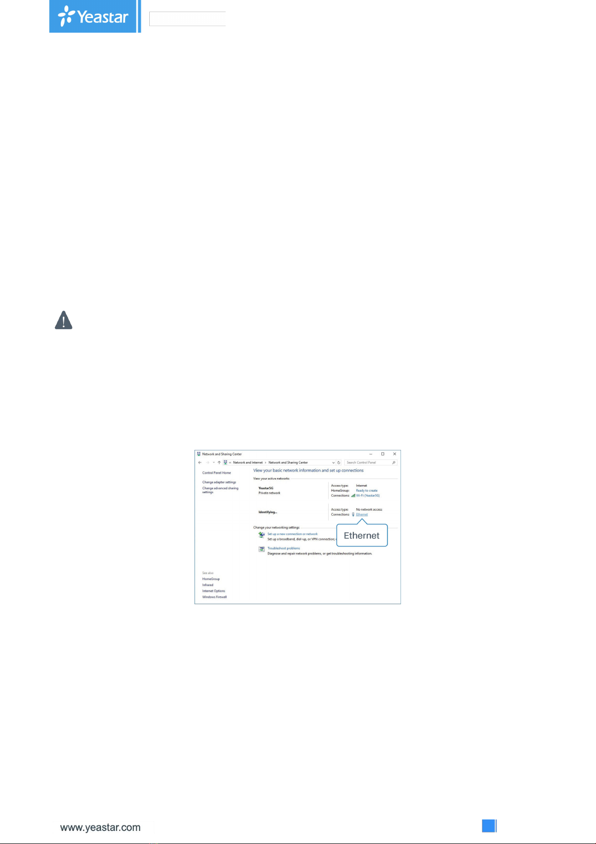
Connect PC to UF51 LAN port directly or through PoE injector. The following steps are based on
Windows 10 operating system for your reference.
A. Go to “Control Panel” →“Network and Internet” →“Network and Sharing Center”, then click
“Ethernet” (It may have different names).
B. Go to “Properties” →“Internet Protocol Version 4(TCP/IPv4) ”, select “Obtain an IP address
automatically” or “Use the following IP address”, then assign a static IP manually within the same
subnet of the device.

14
C. Open a Web browser on your PC (Chrome is recommended) and type in the IP address 192.168.1.1
to access the web GUI.
D. Enter the username and password, click “Login”.
If you enter the username or password incorrectly more than 5 times, the login page will be
locked for 10 minutes.
Table of contents
Other Yeastar Technology Switch manuals


