AVGear AVG-DMM1616 User manual

AVG-DMM1616
The AVG-DMM1616 is a high-performance
video and audio modular matrix switcher
supporting a maximum of 16 input signal
sources and 16 output displays synchronously.
Features
Modular chassis with configurable
I/O slots, ranging from 4x4 to
16x16.
Various I/O cards, includes HDMI,
HDBaseT, SD/HD/3G-SDI, DVI
and VGA cards (Compatible with
YUV, YC & CVBS.) to configure
any matrix.
True cross-point switching, any
input to any output, regardless of
signal format.
Supports HDMI1.4a, supports 3D.
Supports 4K.
Integrated HDBaseT technology.
Controllable via button, RS232 &
optional TCP/IP, also compatible
with 3rd party control systems.
HDCP compliant.
LCD display.

AVG-DMM1616
PLEASE READ THIS PRODUCT MANUAL CAREFULLY
BEFORE USING THIS PRODUCT.
This manual is only for operation instruction only, and
is not to be used in a maintenance capacity. The
functions described in this version are current as at
March 2015. Any changes of functions and
operational parameters will be updated in future
manual versions. Please refer to your dealer for the
latest product details.
Version 1.0 1/3/15

AVG-DMM1616
SAFETY OPERATION GUIDE
In order to guarantee the reliable operation of the equipment and safety of the
user, please abide by the following procedures in installation, use and
maintenance:
1. The system must be earthed properly. Please do not use two blade plugs
and ensure the AC power supply ranges from 100v to 240v and from 50Hz
to 60Hz.
2. Do not install the switcher in an environment where it will be exposed to
extreme hot or cold temperatures.
3. This unit will generate heat during operation, please ensure that you allow
adequate ventilation to ensure reliable operation.
4. Please disconnect the unit from mains power if it will be left unused for a
long time.
5. Please DO NOT try to open the casing of the equipment, DO NOT attempt to
repair the unit. Opening the unit will void the warranty. There are high
voltage components in the unit and attempting to repair the unit could result
in serious injury.
6. Do not allow the unit to come into contact with any liquid as that could result
in personal injury and product failure.

AVG-DMM1616
TABLE OF CONTENTS
Introduction ..............................................................................................................1
Introduction to the AVG-DMM1616...............................................................1.1
Features.......................................................................................................1.2
MMX signal card (changeable cards)
................................................1.2.1
What’s in the Box........……………………………………………………………………2
Product Appearance of the AVG-DMM1616...........................................................3
Front Panel...................................................................................................3.1
Rear Panel....................................................................................................3.2
Changeable Cards........................................................................................3.3
4I-DV & 4O-DV
................................................................................3.3.1
4I-DS& 4O-DS
.................................................................................3.3.2
4I-HD & 4O-HD
................................................................................3.3.3
4I-VG & 4O-VG
................................................................................3.3.4
4I-VA
...............................................................................................3.3.5
4I-SD & 4O-SD
................................................................................3.3.6
4I-TP & 4O-TP
.................................................................................3.3.7
4I-UH & 4O-UH
................................................................................3.3.8
4I-UF & 4O-UF
.................................................................................3.3.9
4I-BT & 4O-BT
...............................................................................3.3.10
System Connection..................................................................................................4
System Applications.....................................................................................4.1
Usage Precautions.......................................................................................4.2
Connection Diagram.....................................................................................4.3
System Operations...................................................................................................5
Front Panel Button Control...........................................................................5.1
IR Control.....................................................................................................5.2
RS232 Control..............................................................................................5.3
Connection with the RS232 Communication Port...........................5.3.1
RS232 Communication Commands................................................5.3.2
TCP/IP Control .............................................................................................5.4
Control Modes ................................................................................5.4.1
TCP/IP Settings..............................................................................5.4.2
Specifications...........................................................................................................6
Main Unit......................................................................................................6.1
Changeable Cards........................................................................................6.2
4I-DV & 4O-DV
................................................................................6.2.1
4I-DS& 4O-DS
.................................................................................6.2.2
4I-HD & 4O-HD
................................................................................6.2.3
4I-VG & 4O-VG
................................................................................6.2.4

AVG-DMM1616
4I-VA
...............................................................................................6.2.5
4I-SD & 4O-SD
................................................................................6.2.6
4I-TP & 4O-TP
.................................................................................6.2.7
4I-UH & 4O-UH
................................................................................6.2.8
4I-UF & 4O-UF
.................................................................................6.2.9
4I-BT & 4O-BT
...............................................................................6.2.10
Troubleshooting & Maintenance.............................................................................7

AVG-DMM1616
1. Introduction
1.1. Introduction to the AVG-DMM1616
The AVG-DMM1616 is a high-performance video and audio modular matrix switcher
from our Digital Media Matrix range. It supports a maximum of 16 input signal
sources and 16 output displays synchronously. It supports different video signals
with true cross-point switching. Every video and audio signal is transmitted and
switched independently to decrease signal attenuation. The AVG-DMM1616
supports various interchangeable cards including HDMI, 4K, DVI, VGA, SDI, Fiber
Optic and HDBaseT etc, and all the cards support hot plug & play. Users can choose
to insert different signal cards for different applications.
The AVG-DMM1616 has a power fail memory function and audio can break away
from or follow the video switched. It has an RS232 port for serial control and an
optional IP port for TCP/IP control, it can also be easily controlled by third-party
devices.
With its flexible design, the AVG-DMM1616 can be used for a range of projects and
is capable of being an ‘all-in-one solution’. It is the perfect solution for multimedia
conference rooms, control rooms, broadcasting rooms, shopping centers etc. It is
comfortable handling all the audiovisual management, including the switching,
driving, scaling etc.
1.2. Features
Modular chassis with configurable I/O slots, ranging from 4x4 to 16x16.
Various I/O cards, includes HDMI, HDBaseT, SD/HD/3G-SDI, DVI and VGA
cards (Compatible with YUV, YC & CVBS.) to configure any matrix.
True cross-point switching, any input to any output, regardless of signal format.
Supports HDMI1.4a, supports 3D, 4K cards available.
Integrated HDBaseT technology.
Controllable via button, RS232 & optional TCP/IP, also compatible with 3rd
party controllers.
HDCP compliant.
LCD display.

AVG-DMM1616
1.2.1. MMX signal card (changeable cards)
To suit different applications and users, the AVG-DMM1616 cards are classified into
the following models:
Spec
Models
Inputs Signal Format
4I-HD 4 HDMI
4I-DV 4 DVI
4I-DS 4 DVI, HDMI, VGA, AV,
YPbPr
4I-VG 4 VGA
4I-VA 4 VGA& PCM audio
Spec
Models
Inputs Signal Format
4I-SD 4 inputs & 4 LOOP outputs
for each channel) SDI
4I-TP 4 HDMI TP, IR, RS232
4I-UH 4 HDMI& PCM Audio
4I-UF 4 Optical Fiber
4I-BT 4 HDBT, RS232, Audio
Input Cards
Spec
Models
Outputs Signal Format
4O-HD 4 HDMI
4O-DV 4 DVI
4O-DS 4 DVI, HDMI, VGA, AV,
YPbPr
4O-VG 4 VGA, 4 Stereo audio VGA, analog audio
4O-SD 4 outputs & 4 LOOP
outputs for each channel) SDI
4O-TP 4 HDMI TP, IR, RS232
4O-UH 4 HDMI& PCM Audio
4O-UF 4 Optical Fiber
4O-BT 4 HDBT, RS232, Audio

AVG-DMM1616
2. Package List
1 x AVG-DMM1616
1 x RS232 cable
4 x Plastic cushions
1 x IR remote (The cell battery is not included)
1 x Power Cord
1 x User manual
Note: Please confirm if the product and the accessories are all included, if not,
please contact your dealer.

AVG-DMM1616
3. Product Appearance of the AVG-DMM1616
3.1. Front Panel
No.
Name
Description
①
IR IR sensor, receives IR signal sent from IR remote
②
Power
indicator Illuminates red once powered on
③
LCD screen Displays real-time operation status
④
INPUTS Buttons for input channels with green back-light indication,
ranges from 0~ 9, 16 selectable channels in total.
⑤
OUTPUTS Buttons for output channels with green back-light indication,
ranges from 0 ~ 9, 16 selectable channels in total.
⑥
MENU
AV
: transfer video and audio signal synchronously
,
: division button, to divide the output channels when
switching to more than one channel.
UNDO
: Undo button, to resume to the status before the
command just performed.
ENTER
: confirm switching operation. Operation will not be
executed by the matrix without confirmation.
ALL:
select all input/output channel
THROUGH
: To transfer the signals directly to the
corresponding output channels.
: Backspace button, to backspace the latest input button.
Note: Pictures shown in this manual are for reference only.
AVG-DMM1616
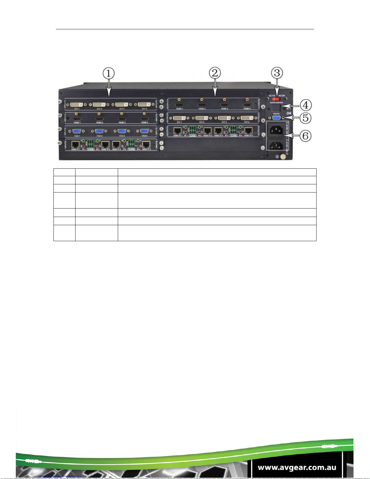
3.2. Rear Panel
No. Name
Description
①
INPUTS Input signal card slots, 4 in total
②
OUTPUTS Output signal card slots, 4 in total
③
Power
switch Switch between AC110V and AC230V to access different
power
④
TCP/IP (Optional) Used for TCP/IP control port
⑤
RS232 Serial control port, connect with RS232 port of control device.
⑥
Power ports
Connect with household alternating current power, including
one redundant power.
Note: There are only 4 input and 4 output slots for AVG-DMM1616, which enables
only 4 input cards and 4 output cards to be installed on AVG-DMM1616. The
input/output cards can be changed based on your requests and supports hot plug
and play.
Pictures shown in this manual are for reference only.
3.3. Changeable Cards
AVG-DMM1616 support expansion through various changeable input/ output cards
of different signals including DVI, HDMI, VGA, twisted pair, SDI etc. Here is a brief
introduction to the changeable cards.

AVG-DMM1616
3.3.1. 4I-DV & 4O-DV
DVI signal card. (Please check the specification from 5.2.1) It is fully compatible with
HDMI1.3 and HDCP, but not supporting analog signals. It uses embedded EDID
management technology, supporting DDC. 4I-DV: input card, maximum four input
signals. Input signals can pass to an output device through 4O-DV, or pass through
other series output cards.
4O-DV: output card, maximum four output signals, output signals from 4I-DV, or
other series of input cards.
Pin Layout of the DVI-I connector (Dual-Link). (Female)
PIN
Function
PIN
Function
1 T.M.D.S.Data2- 13 T.M.D.S.Data3+
2 T.M.D.S.Data2+ 14 +5V Power
3 T.M.D.S. Data 2/4 Shield 15 Ground (return for
+5V, Hsync and
Vsync)
4 T.M.D.S. Data 4- 16 Hot Plug Detect
5 T.M.D.S. Data 4+ 17 T.M.D.S. Data 0-
6 DDC Clock 18 T.M.D.S. Data 0+
7 DDC Data 19 T.M.D.S. Data 0/5
Shield
8 Analog Vertical Sync 20 T.M.D.S.Data5-
9 T.M.D.S.Data1- 21 T.M.D.S.Data5+
10 T.M.D.S.Data1+ 22 T.M.D.S. Clock
Shield
11 T.M.D.S.Data1/3 Shield 23 T.M.D. S. Clock +
12 T.M.D.S.Data3- 24 T.M.D.S .Clock-

AVG-DMM1616
3.3.2.
4I-DS& 4O-DS
Seamless DVI signal card. (Please check the specification from 5.2.2)
It is fully compatible with HDMI1.3 and HDCP 1.2, and supports seamless
transmission for high-definition DVI, HDMI, VGA, AV, YPbPr signals. It can
automatically identify the format of the input signal, and the output resolution can be
adjusted.
It uses embedded the EDID management technology, supporting DDC. 4I-DS:
seamless input card, maximum four input signals. Input signals can pass to output
devices through 4O-DS, or pass through the other series of output cards.
4O-DS: seamless output card, maximum four output signals. Output signals can
come from 4I-DS, or from the other series input cards. It supports memory off
function for resolution, signal format and HDCP compliance status.
Note: When 4O-DS works with input cards except 4I-DS, adjust the 4 input signals
to any one of the following 5 resolutions to enable seamless output: 1024x768,
1280x720, 1600x1200, 1920x1080, 1920x1200. DVI interfaces on the signal card
are the same as the interfaces on 4I-DV& 4O-DV.
3.3.3. 4I-HD & 4O-HD
HDMI signal card. (Please check the specification from 5.2.3) It uses embedded
EDID management technology, supporting DDC. It is also compatible with DVI signal
(HDCP required). 4I-HD: input card, maximum four input signals. Input signals can
pass to an output device through 4O-HD, or pass through other series output cards.

AVG-DMM1616
4O-HD: output card, maximum four output signals, output signals from 4I-HD, or
other series input cards.
Pin layout of the HDMI connectors (female).
3.3.4. 4I-VG & 4O-VG
VGA signal card. (Please check the specification from 5.2.4) Scale all inputs to
1080p. Compatible with C-Video, YUV, YC (Factory preset function). The bandwidth
is up to 350MHz (-3dB);
Supporting RGBHV, RGsB, RGBS, RsGsBs, YUV, YC and Composite video. 4I-VG:
input card, maximum four input signals. Input signals can pass to output devices
through any series output cards.
4O-VG: output card, maximum four VGA output signals and 4 stereo audio outputs,
output video signal from 4I-VG, or other series input cards, outputs audio signal from
the audio of the input signal.
No.
Signal Name
No.
Signal Name
1
TMDS Data 2+
20
SHELL
2
TMDS Data 2 Shield
19
Hot Plug Detect
3
TMDS Data 2-
18
+5V Power
4
TMDS Data 1+
17
Ground
5
TMDS Data 1 Shield
16
DDC Data
6
TMDS Data 1-
15
DDC Clock
7
TMDS Data 0+
14
No Connect
8
TMDS Data 0 Shield
13
CEC
9
TMDS Data 0-
12
TMDS Clock-
10
TMDS Clock+
11
TMDS Clock Shield
AVG-DMM1616
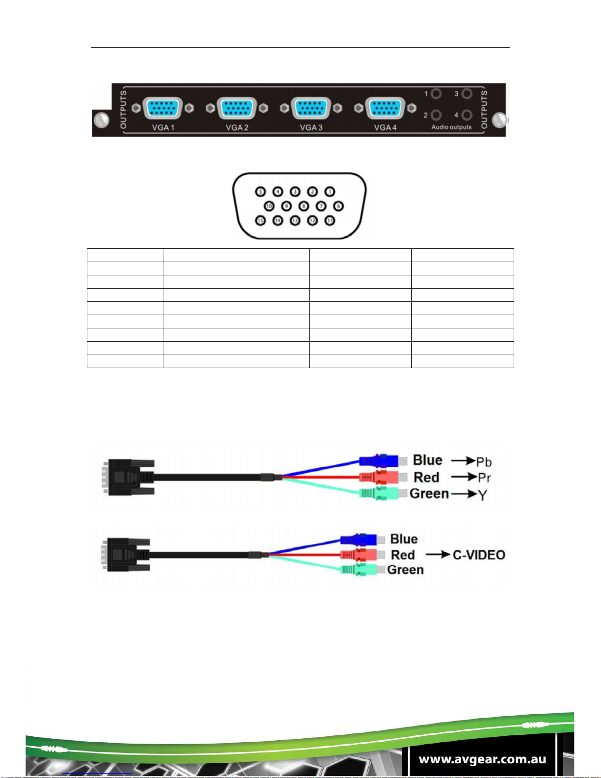
Pin layout of the VGA connectors (female):
Pin Number
Signal Name
Pin Number
Signal Name
Pin 1 RED Pin 9 KEY/PWR
Pin 2 GREEN Pin 10 GND
Pin 3 BLUE Pin 11 ID0/RES
Pin 4 ID2/RES Pin 12 ID1/SDA
Pin 5 GND Pin 13 HSync
Pin 6 RED_RTN Pin 14 VSync
Pin 7 GREEN_RTN Pin 15 ID3/SCL
Pin 8 BLUE_RTN
Connect the devices via VGA converting cable as shown below:
Connect with Component Video (YPbPr) Source
Connect with Composite Video (C-VIDEO) Source

AVG-DMM1616
3.3.5. 4I-VA
VGA signal card. (Please check the specification from 5.2.5) Scale all inputs to
1080p. Compatible with C-Video, YUV, YC (Factory preset function). Supporting
RGBHV, RGsB, RGBS, RsGsBs, YUV, YC and Composite video.
4I-VA: input card, maximum four VGA inputs and four stereo audio inputs. Input
signal can pass to output devices through any series of output cards.
The VGA connector and source connection is same with the 4I-VG.
3.3.6. 4I-SD & 4O-SD
SDI signal card. (Please check the specification from 5.2.6) It is compatible with
different SDI signal formats, including SD/HD/3G-SDI (adaptive) Every port has a
loop output for local monitoring.
4I-SD: input card, maximum four input signals. Input signals can pass to output
devices through 4O-SD, or pass through other series output cards.
4O-SD: output card, maximum four output signals, output signals from 4I-SD, or
other series input cards.
The BNC connector is shown as the figure below.

AVG-DMM1616
3.3.7. 4I-TP & 4O-TP
Twisted pair card (HDMI/DVI extender). (Please check the specification from 5.2.7)
Supports HDTV, compatible with HDMI1.3 and HDCP 4I-TP: input card, maximum
input four HDMI TP signals. Input signals can pass to output devices through 4O-TP,
or pass through other series output cards, designed to work with the AVG-
TPHD402T.
4O-TP: output card, maximum output four HDMI TP signal, output signals from 4I-
TP, or other kinds of input cards, designed to work with the AVG-TPHD402R.
Pin layout of the RJ45 connectors:
Two different connection standards can be chosen; the connectors of the same
cable should use the same standard at each end.
TIA/EIA T568A
TIA/EIA T568B
Cable color
Cable color
1 green white 1 orange white
2 green 2 orange
3 orange white 3 green white
4 blue 4 blue
5 blue white 5 blue white
6 orange 6 green
7 brown white 7 brown white
8brown 8brown

AVG-DMM1616
Note: Cable connectors MUST be metal, and the shielded layer of the cable MUST
be connected to the connector’s metal shell, to ensure reliable grounding.
3.3.8. 4I-UH & 4O-UH
4K HDMI signal card. (Please check the specification from 5.2.8) Supports hot-
plugging, HDMI 1.4& HDCP 1.4 compliant; Compatible with DVI signal; Supports
high-definition HDMI sources up to 4kx2k, 1080p 3D compliant; Provides auxiliary
audio port to output the HDMI embedded audio. It uses embedded EDID
management technology.
4I-UH: input card, maximum four input signals. Input signals can pass to output
devices through 4O-UH, or pass through other series output cards.
4O-UH: output card, maximum four output signals, output signals from 4I-UH, or
other series input cards, HDCP compliant status set via RS232 command.
3.3.9. 4I-UF & 4O-UF
4K optical signal card. (Please check the specification from 5.2.9) Supports hot-
plugging; High bandwidth: 10.2Gbps; Compliant with HDMI 1.4, able to transmit
4K×2K& 1080P 3D (max) signals; Supports multi-mode transmission up to 300m and
single mode transmission up to 1km.
4I-UF: input card with indicators, maximum four input signals, corresponding
indicator illuminates green when there is an input signal. Input signals can pass to
output devices through 4O-UF, or pass through other series output cards.

AVG-DMM1616
4O-UF: output card with indicators, maximum four output signals, output signals from
4I-UF, or other series input cards; corresponding indicator illuminates green when
there is an output signal.
Note: Use the 4I-UF/ 4O-UF with optical fiber transmitter/ receiver.
3.3.10. 4I-BT & 4O-BT
Twisted pair card (HDMI/DVI extender). (Please check the specification from 5.2.10)
Supports hot-plug, supports HDTV, compatible with HDBT 1.0, HDMI1.4a&
HDCP1.4; Wide resolution range from 480p to 4kx2k, 1080p 3D compliant; Extends
HDBT signals up to 70m at 1080p or 40m at 4k; Bi-directional RS232 transmission
on a single cable; Auxiliary audio ports support a stereo signal. It uses embedded
EDID management technology.
4I-BT: input card, maximum input four HDMI TP signals. Input signals can pass to
output devices through 4O-BT, or pass through other series output cards, designed
to work with the HDBT transmitter AVG-TPHD402T.
4O-BT: output card, maximum output four HDBT signal, output signals from 4I-BT, or
other series input cards, designed to work with the HDBT receiver AVG-TPHD402R.

AVG-DMM1616
4. System Connection
4.1. System Applications
Reliable performance for control and transmission makes the AVG-DMM1616 ideal
in the IT computer space, signal monitoring, big screen displays, conference
systems, television broadcast, education, banking and security institutions etc.
4.2. Usage Precautions
1. System should be installed in a clean environment with temperature and humidity
maintained to within equipment specification.
2. All of the power switches, plugs, sockets and power cords should be insulated
and safe.
3. All devices should be connected before power is turned on.
4.3. Connection Diagram

AVG-DMM1616
5. System Operations
5.1. Front Panel Button Control
Users can control the AVG-DMM1616 simply and directly with its front panel buttons.
To switch AV/ and A/ V signal, please operate the buttons using the following format:
Format: “Input Channel” + “AV” +“Output Channel “+“Enter”
Note:
1) “Switch Mode”: Audio & Video synchronous (AV) or break away switching mode
(Audio/ Video)
2) “Input Channel”: Push the number of the input channel to be controlled,
3) “Output Channel”: Push the number of the output channels to be controlled. Press
“All” to select all the outputs.
4) Use “,” button to separate multiple I/O channels, and press the “ENTER” button to
confirm the operation.
5) The input/output channels on the rear panel are slotted from left to right, top to
bottom.
6) The input delay time between two numbers of every input & output channel must
be less than 5 seconds; otherwise the operation will be cancelled.
Example:
1. To transfer input 1 to output 11, press input “1”, output “0” “1” and “Enter”.
2. To transfer signals from input 1 to all output channels, press buttons in this order:
“1”, “All”.
Other Functional Buttons:
Buttons
Description
Operation
UNDO
Returns to the
previous
status
State 1: Input 6 -> output 6 Press input “6” + “AV”+
output 4 to change the connection. Press “Undo” to
return to State 1.
Backspace
the last
operation
If you press buttons “1”, “AV”, “2”, “” in order, then “2”
will be canceled.
THROUGH
Get one to
one I/O
connection,
e.g. input 1->
output 1,
input 2->
output 2.
Format: “Input Channel”+”Through” If you press
buttons “ALL”, “THROUGH” in order, then the result
will be like input 1output 1, input 2output 2, input
3output 3 … input 16output 16.
Table of contents
Other AVGear Switch manuals

AVGear
AVGear AVG-HDE2 User manual

AVGear
AVGear AVG-SC121D-TN User manual

AVGear
AVGear AVG-SC42T User manual

AVGear
AVGear AVG-SC91T User manual

AVGear
AVGear AVG-CSK-HD44 User manual

AVGear
AVGear AVG-SC51D User manual

AVGear
AVGear AVG-DSS61 User manual

AVGear
AVGear AVG-UHS24 User manual

AVGear
AVGear MHD44 User manual

AVGear
AVGear AVG-SC51T User manual


