YELLOWRIVER YR-COB100W User manual

100W White COB LED
Model:YR-COB100W

Contents
Section 1.Getting Started
Unpacking
Safety Instruction
Section 2. Set Up
Installation
Controlling Board
Machine Connection
Section 3. troubleshooting
Troubleshooting
Section 4. Reference
Control Menu
DMX Protocol
Dimmer Curve
Specification
Section 1.Getting Started
Unpacking
Safety Instruction
Unpacking
1pc Fixture
1/4pc Signal Convertor Cable
1pc User Manual
Thanks for choosing our product. Carefully unpack the box and check the contents to
ensure that all parts are present and in good conditions. If anything damaged in transit,
notify the shipper immediately and keep the packing material for inspection. Again, please
save the carton and all packing materials. If a fixture must be returned to manufacturer, it
is important that the fixture be returned in the original manufacturer box and packing.

Safety Instruction
Please conserve this manual as operation guidance. If you sell this product to other user,
please make sure that they also receive this user manual.
Always make sure that you are connecting to the proper voltage and that the line
voltage you are connecting to is not higher than that stated on the decal or rear panel of
the fixture.
If the fixture is intended to indoor use only. To prevent risk of fire or shock, do not
expose fixture to rain or moisture. Make sure there are no flammable, explosive or
corrosive materials surrounded in 10meters while operating.
The unit must be installed in a location with adequate ventilation, at least 5m away from
adjacent surfaces. Be sure that no ventilation slots are blocked.
Some fixture may carry high heat, do not aim at objective more than 2minutes.
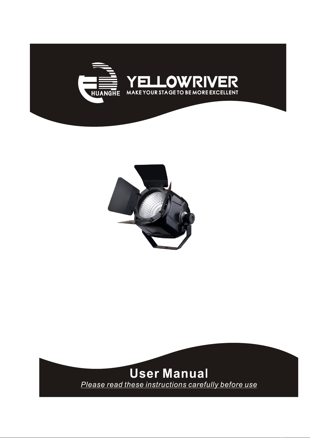
Safe rope should be used to install machine. Bearing of safe rope should be more than
3times of the machine weight. Complimentary signal cable transmits signals to 20 unit
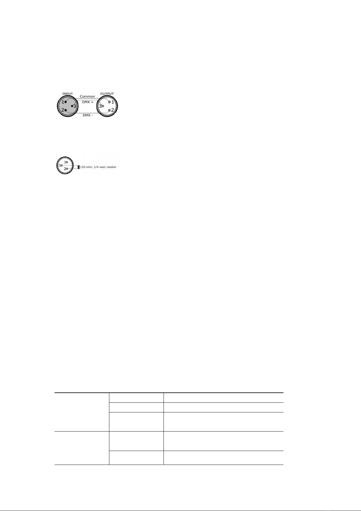
fixtures at most. Signal amplifier is a must to connect more fixtures. And a terminal
should be added at the end of last fixtures’ DMX sockets, 120 Ohm, 1/4W resistance
need welding between Pin 2 and Pin3.
Always disconnect from the power source before servicing or replacing fuse/lamp and
be sure to replace with same fuse/lamp size and type. Cut off power before moving,
repairing and cleaning the machine.
To avoid electric shock, all fixtures must be connected to circuits with a suitable earth
connection.
Always secure fixture using a safety chain and carrying handles.
Do not operate at ambient temperatures higher than 104℉(40℃).
The power cable for this fixture is 0.5 m㎡, please mind the safety requirements in
actual using, if any wrong operation, our company takes no responsibility for any loss.
Also, make sure the power cord is never crimped or damaged.
In case of failure or mis-function occurred, stop using immediately. Never try to repair
the fixture by yourself. Repairs carried out by unskilled people can lead to damage or
malfunction. Please contact the nearest authorized technical assistance center. Buy the
same spare parts/components from manufacturer directly.
Avoid direct eye exposure to the light source while it is on.
Do not power on and power off the fixture frequently
When use DMX controller, please make sure that there is no interference sources(e.g.
intercom, high frequency radio waves and radiation source)
Caution! There are no user serviceable parts inside the unit. Do not open the housing or attempt any
repairs yourself. In the unlikely event your unit may require service, please contact your local distribution
For your safe, please read this user manual carefully before turn on
the fixture. This machine should be operated by qualified engineer!

or after-sale service center.
Section 2. Set Up
Installation
Controlling Board
Machine connection
Installation
This machine should be mounted through the screw holes of truss. Safety rope is a
must to fix fixture well. Make sure truss and safety rope have strong load capacity to
bear more than 3 times of machine weight .
This machine should be installed by qualified technician.

Controlling Board
MENU UP DOWN ENTER
Front display panel
1. LED Display Panel
2. Button
Menu
Switch menu function
UP
Scroll upwards
DOWN
Scroll downwards
ENTER
Confirm by pressing ENTER
3. DMX Signal Input
3 PIN XRL port for DMX512 signal input ( daisy chain);
4. DMX signal output
3 PIN XRL Port for DMX512 signal output ( daisy chain);
5. Power Input
AC power cable port input

Cable Connectors
Cables must have a male XLR connector on one end and a female XLR connector on the other end.
A word on termination: DMX is a resilient communication protocol, however
errors still occasionally occur. Termination reduces signal errors, and therefore best practices include
use of a terninator in all circumstances. If you are experiencing problems with erratic fixture behavior,
especially over long signal cable runs, a terminator may help improve performance.
To build your own DMX Terminator: Obtain a 120-ohm, 1/4-watt resistor, and
wire it between pins 2&3 of the last fixture. They are also readily available from specialty retailers.
Master and slave: select one machine as master, press the menu to choose the function
you want. Press other machines’ address to be DMX state. Use signal cable to connect
machines one by one. Then slave machines will run the same as master machine.
Use controller to control lot of machines: if all machines are set the same menu data, or
different manual data, after use signal cable to connect to controller, all machines will be
controlled by controller. (before connect to controller, all machines should be in the same
channel mode 3ch or 1ch).
Section 3. Troubleshooting
Problem
Probable Cause(s)
Remedy
No power to fixture
Check power cables
Primary fuse blown
Replace fuse
No response from
fixture when power
is applies
Secondary fuse
blown
Replace fuse
Controller not
connected
Connect controller
Fixture resets but
does not respond
correctly to
Incorrect
Check address setting on fixture and controller

addressing of the
fixtures
Bad data link
connection
Inspect cables and correct poor connections
and/or broken cables.
Conflict between
tracking and vector
control
Eliminate scene cross-fade on controller
Data link not
terminated
Insert termination plug in output of last fixture
controller(DMX
mode operation)
Defective fixture or
2 devices
transmitting on link
Bypass fixtures one at a time until normal
operation is regained: unplug both connectors
and connect them directly together
Colors cannot be
mixed
Random color
mixing is on
Turn off random color mixing
Fixture does not
reset correctly
Electronic or
mechanical failure
Contact service technician
Lamp missing or
blown
Disconnect fixture and replace lamp
No light, lamp cuts
out intermittently, or
burns out too
quickly
Fixture or lamp is
too hot
Allow fixture to cool. If problem persists,
contact service technician
Section 4. Reference
Control Menu
DMX Protocol
Dimmer Curve
Specification

Control Menu
No.
Menu
Function
1
d3--
DMX 3 channel control(need connecting controller)
2
d.1-
DMX 1 channel control(need connecting controller)
3
n---
r000 to r255: White from dark to bright
4
F---
F000 to F255:flash speed,from slow to fast
5
T---
on: high temperature with half power function on
off:high temperature with half power function off
When the LED board temperature increase up to be 80℃,
the Max. power consumption of LED source would be
50% ; When the LED source temperature decrease to
be 58 ℃ , the Max. power consumption of LED source
would be 100% ;
6
dr--
dr-0:Standard Dimmer Curve;
dr-1:Dimmer Curve1;
dr-2:Dimmer Curve2;
dr-3:Dimmer Curve3;
dr-3:Dimmer Curve4;
DMX protocol
DMX512 Channel Chart:(3CH)
CH
Function
Specification
CH1
Dimmer
0-255 White Dimmer, from dark to bright
CH2
Flash
1-255 flash speed,from slow to fast
CH3
Macro function
000-020:Standard Dimmer Curve;
021-040:Dimmer Curve1;
041-060:Dimmer Curve2;
061-080:Dimmer Curve3;
081-100:Dimmer Curve4;
101-149:No Function;
150-155: after 3 second, high temperature
with half power function off;
156-199:No Function;
200-205:after 3 second, high temperature
with half power function on;
206-255:No Function;
DMX512 Channel Chart:(1CH)
CH
Function
Specification
CH1
Dimmer
0-255 White Dimmer, from dark to bright

Dimmer Curve:
Ramp Effect
Menu
Tup(ms)
Tdown(ms)
Standard Dimmer
Curve
dr-0
0
0
Dimmer Curve 1
dr-1
980
1010
Dimmer Curve 2
dr-2
1210
1320
Dimmer Curve 3
dr-3
1600
1710
Dimmer Curve 4
dr-4
1850
1980
Specification
Voltage:AC110V-240V
Frequency:50/60Hz
Machine Power:100W
LED source: 100W White LED(Pure white(6000-6500K)/Warm white(3000-3200K)/Cold
white(7500-8000K)/
LED QTY:1pcs
Strobe: 0~20 Hz
Dimmer : 4 kinds of dimmer methods
Fan: 1pcs temperature detect fan
Noise: Same as Ambient noise away 1.5m
Beam Angle:60° ( can be changed by barn door)
Control Mode:DMX512/Manual
Channel:3/1CH(switchable)
Net weight:1.5kg
Size:26*26*11.5cm(excluding bracket)

本公司有权对此份产品说明书进行修改,恕不另行通知。
Our company reserve right to revise this user manual without notice!
Innovation | Efficiency | Dedication | Harmonious

Table of contents
Other YELLOWRIVER Spotlight manuals