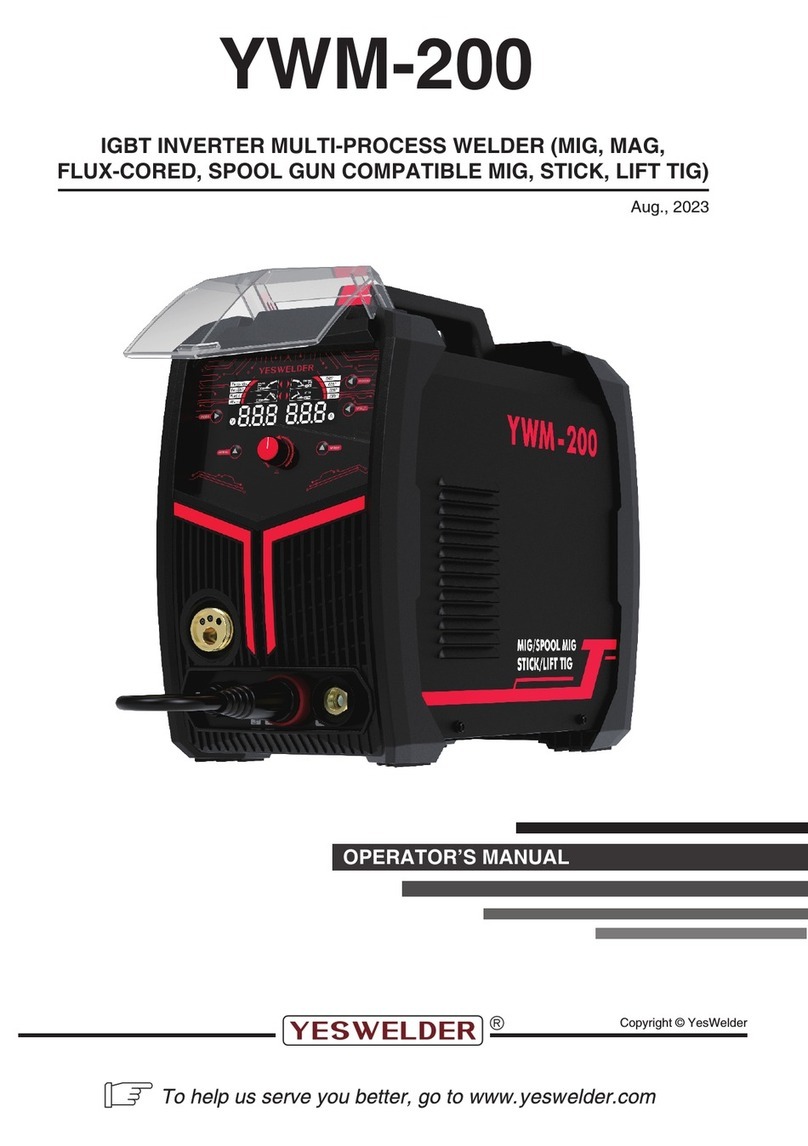
Yeswelder MIG PRO-200 User manual

IGBT INVERTER CO2/MIG WELDING MACHINE
PRODUCT MODEL: MIG PRO-200,MIG PRO-250
USER MANUAL
(READ THE MANUAL CAREFULLY BEFORE INSTALLATION, USE & MAINTENANCE)

Catalogue
1. Safety tips..................................................................................................................................................3
2. General introduction..................................................................................................................................4
3. Electrical diagrams....................................................................................................................................4
4. Main Parameter......................................................................................................................................... 5
5.
Installation.........................................................................................................................................................6
Ⅰ. Power Input Cable.......................................................................................................................................6
Ⅱ. Power Output Cable.................................................................................................................................... 6
Ⅲ. Installation of Wire Spool............................................................................................................................ 6
6. Operation.......................................................................................................................................................7
Ⅰ. Operation Way............................................................................................................................................ 7
Ⅱ. Setup of the Welding Current..................................................................................................................... 7
Ⅲ. Welding Parameter List. (For Low-carbon Steel)....................................................................................... 7
Ⅳ. Setup of Welding Speed.............................................................................................................................8
Ⅴ. Setup of Dry Extension of Welding Wire.................................................................................................... 8
Ⅵ. Setup of CO2 Flow..................................................................................................................................... 8
7. Attention........................................................................................................................................................8
Ⅰ.Work Environment........................................................................................................................................8
Ⅱ. Safe tips.......................................................................................................................................................8
8. Maintenance................................................................................................................................................. 9
9. Fault and repair........................................................................................................................................... 10
Ⅰ.Welding Power Supply............................................................................................................................... 10
Ⅱ.Welding Torch............................................................................................................................................ 10
Ⅲ.Wire
Feeder.............................................................................................................................................................11
Ⅳ.Power Output Cable.................................................................................................................................. 11
PROMISE
We make a solemn promise: The machine is produced under Chinese & International quality
standard, accord with IEC60974-1 International safety standard. The design & technology of the
products are protected by patent. The products are guaranteed for one year from purchase date.
Please read user manual carefully before operation.

1.Safety tips
During the welding process, the work may cause some damage to you and other people, so please make
some protection. For more details, please kindly read “operator safety manual” accord with accident
prevention of manufacturer
Worker must receive professional training before operation!
● Use welding safety products recognized by national safety ministry of supervision.
● Worker must be the special operator with valid certificate of metal welding work.
● During maintenance & repair, please disconnect the line of electricity.
Electric shock: it may cause some injure and even fatal.
● Connect the earth cable according to standard regulation.
● Avoid all contact with live components of the welding circuit, electrodes and wires
with bare hands.
● The operator should keep the workpiece & earth insulating from himself/herself.
● Make sure the work place on safe situation.
Smoke-may be bad for people’s health.
● Keep your head out of smoke & welding gas in order to avoid breathing it.
● Keep the working area in good ventilation during welding.
Arc light emission: harmful to people’s eyes & skin.
● To protect your eyes and body, please wear welding helmet, work clothes & gloves.
● People in or near the working area should be protected under welding helmet & other protection
equipment.
Fire or explosion hazard may be caused by misoperation.
● Welding fire flame may cause fire, please keep the inflammable substance far from
workpiece and keep fire safety.
● Make sure fire extinguisher nearby with a professional fire worker here, who can be
skillful with fire extinguisher.
● Don’t weld the closed container.
Don’t use this machine for pipe unfreeze.
Hot workpiece may scald your hand.
● Don’t contact the hot workpiece with bare hand.
● During welding continuously for a long time, the welding torch should have some time to release hot.
Magnetic field will affect heart pacemaker.
● The heart pacemaker user will keep far away from welding area before having some inquiry from doctor.
Moving component will cause some damage to people.
● Keep away from moving component, such as fan.
● Keep the panel, back plate, cover and protection equipment fasten on machine
Fault—you should look for some help from professional worker when you face some trouble.
● If you face some trouble on installation and operation, please check the machine according to the
operation manual.
● After your reading on operation manual, still can’t understand something or can’t solve the trouble,
please should contact with your supplier or our company service center for professional help.

2. General introduction
MIG PRO-200,MIG-250 PRO-250 CO2/MIG/GASLESS MIG/MMA/LIFT TIG Welding Machines are
manufactured based on the internationally advanced inverter technology.The working principle is to invert
50/60Hz alternative current into direct current first. Then the direct current is inverted into high frequency
alternative current (20KHz) by IGBT components before it is rectified. Machines in this series have features
as follow:
★ IGBT Inverter technology, current mode control. Reliable quality and stable performance.
★ Closed circuit feedback with constant voltage output. Good resistance to voltage fluctuation. (
±
15%)
★ Electric reactor control, stable welding process with little splash, deep welding pool and beautiful welding
seam.
★ Slow wire-feeding for arc start and tip ball removing after welding ensure high success rate of arc start.
★ Suitable for welding thin and medium metal sheet of above 8mm thickness.
★ Small measurement, light weight, easy operation, practical and economical.
★ The efficiency of this machine is above 85%. It saves above 30% energy compared with the conventional
welding machines.
3. Electrical diagrams

4. Main Parameter
MIG PRO 200 MIG PRO 250 MIG PRO 200 MIG PRO 250
RATED POWER INPUT 1Phase 220V±10% 1Phase
220V±10%
1Phase
110/220V±10%
1Phase
110/220V±10%
RATED INPUT POWER
CAPACITY
(
KVA
)
8 11.3 8 11.3
NO-LOAD VOLTAGE (V) 52 52 52 52
OUTPUT CURRENT
ADJUSTMENT
RANGE (A)
50-200
50-250
50-200
50-250
RATED OUTPUT VOLTAGE
ADJUSTMENT
RANGE (V
12.5-30
12.5-30
12.5-30
12.5-30
RATED DUTY CYCLE (%) 60 60 60 60
EFFICIENCY (%) 85 85 85 85
POWER FACTOR (COSΦ) 0.93 0.93 0.93 0.93
TYPE OF WIRE FEEDER INSIDE INSIDE INSIDE INSIDE
GAS POST-FLOW TIME (S) 1±0.5 1±0.5 1±0.5 1±0.5
WIRE FEEDING SPEED
(M/MIN) 2.0-15 2.0-15 2.0-15 2.0-15
DIAMETER OF COIL (MM) 200 200 200 200
EARTH CABLE (MM2) ≥2.5 ≥2.5 ≥2.5 ≥2.5
DIAMETER OF WELDING WIRE
(MM) 0.8/1.0 0.8/1.0 0.8/1.0 0.8/1.0
WELDING THICKNESS (MM) ≥0.8 ≥0.8 ≥0.8 ≥0.8
WEIGHT (KG) 12.5 12.5 14 14
MEASUREMENT (MM) 530X295X400 530X295X400 530X295X400 530X295X400
INSULATION CLASS F F F F
PROTECTION CLASS IP23 IP23 IP23 IP23
5. Installation
Ⅰ. Power Input Cable
Each machine is equipped with power input cable. Connect the cable to AC380V power supply.
Ⅱ. Power Output Cable
Connect the CO
2
gas bottle firmly with the CO
2
inlet on the back of the welding machine by gas-carrying hose.
A gas regulator for the CO
2
gas bottle is needed.

1) Using CO2/MIG,MAG functions, please plug joint into red socket and earth clamp into black socket, plug
the welding torch into the on the front panel and screw it tight. Meanwhile, insert the welding wire into the
welding torch by hand from built in wire feeder.
2)
Using Gasless function,connect, please plug joint into black socket and earth clamp into red socket,plug the
welding torch into the on the front panel and screw it tight. Meanwhile, insert the welding wire into the welding
torch by hand from built in wire feeder.
3) Using MMA and TIG LIFT functions,plug electrode holder into red socket and earth clamp into black
socket.
Ⅲ. Installation of Wire Spool
1). Mount the wire spool with welding wire to the shaft of wire feeder. Lock the wire spool with the spool
holder.
2). Choose a suitable contact tip according to the size of welding wire.
3). Undo the screw of the of wire pressure-wheel and lead the wire into the groove of wire driving wheels via
the wire guide tube. Adjust the pressure wheel to ensure no slippage of wire occurs. But too much pressure
would cause deformation of welding wire and affect the wire feeding speed.
4). Release the welding wire roll by counter clock-wise direction. The head part of the welding wire is always
inserted into the fixing bore on the rim of wire spool to ensure avoid the looseness of wire. So please just cut
the bent head part off while using in order to avoid wire stuck.
5). Choose the correct track of the wire feeding groove by the welding wire diameter.
6). Press the “Inching” button to lead the wire out of the welding torch.


6. Operation
Ⅰ.
Ⅱ. Setup of the Welding Current
The welding current and arc voltage have a direct influence on the stability, quality and efficiency
of welding. So a good coordination of the welding current and arc voltage is required for a high
quality welding. It is decided by the diameter of welding wire, mode of droplet transfer and requirement of
welding efficiency. Regarding the setup of current and voltage for general welding, please consult the form
below. Regarding the different welding requirement, please refer to the “Zoom Table of Welding Parameter”.
Ⅲ.Welding Parameter List. (For Low-carbon Steel)
Welding diameter(MM) Recommended welding current (A) Recommended welding voltage (V)
1.0 20-60 20.8-22.4
1.6 44-84 21.76-23.36
2.0 60-100 22.4-24

2.5 80-120 23.3-24.8
3.2 108-148 23.4-24.93
4.0 104-180 24.6-27.2
Ⅳ. Setup of Welding Speed
The welding speed affects the welding quality and efficiency. Higher welding speed means less
gas-protection, accelerated cooling speed, lower flexibility and forming of welding seam. Lower welding
speed is likely to cause burning through of the workpiece and a puffy welding seam. In the actual production,
please keep the welding speed less than 30m/h.
Ⅴ. Setup of Dry Extension ofWeldingWire
A longer dry extension of welding wire means a deeper penetration, a faster melting of welding wire and a
higher production efficiency. But an excessive length of dry extension is likely to cause burnout of wire and
splash of droplet. So a 10 times length of the welding wire diameter is always chosen in the actual welding
operation.
Ⅵ. Setup of CO2 Flow
The CO
2
flow is rated to the gas protection effect. Besides, the gas protection of inside fillet welding is better
than that of outside fillet welding. So a lower gas flow shall be chosen. For specific digits, please consult the
form below.
Choice of CO2 Flow
Welding Mode Thin Wire/CO2 Shield Thick Wire/CO2 Shield Thick Wire/High Current
/CO2 Shield
CO2 Flow (L/min) 5~15 15~25 25~50
7.Attention
Ⅰ.Work Environment.
(1) The environment should be dry and the air humidity didn’t exceed 90%.
(2) Temperature should be from -10℃ to 40℃.
(3) Avoid welding under rain or hot sunshine, don’t let water or rain into machine.
(4) Don’t work under dust area or aggressive fume.
(5) Avoid using the machine under strong air flow.
Ⅱ. Safe tips.
The machine is equipped with overvoltage, overcurrent and overheat protection device. If the voltage, output
current
and temperature exceed the standard, the machine will stop working. Besides, overusing the machine based
on

exceeded voltage, the machine will be damaged, so please kindly note as below:
(1). Ensure GoodAiriness.
During the working, the machine will generate high temperature and it needs help from fan to cool the
machine. So users please make sure the ventilation inlet is not stuck or covered. Meanwhile, keep the objects
around the machine in a distance of no less than 0.3m. Keeping airiness helps to lower the temperature more
quickly and ensures a longer service life of the machine.
(2). Current Overloading Prohibited
Close attention should be paid to the permissible loading current(the available duty cycle) to ensure the
welding current being under maximum permissible current. Current overloading shortens service life of a
machine greatly, or even damages the machine.
(3). Voltage Overloading Prohibited
For the power supply voltage, please refer to the “Main Parameter Table”. Under normal circumstances, the
auto-compensation circuit in the machine will help to keep the welding current within permissible range.
Voltage overload damages the machine, so preventive measures are needed.
(4). Earth cable connects to the ground. There is a mark near the earth screw on the back panel. Before using
the machine, please choose a wire (cross sectional area above 6 mm
2
) to connect the earth screw to ground
to avoid electricity leakage accident and release static electricity.
(5). No overload of the standard rated duty cycle. When it overloads the standard, the machine will stop
working due to overheat inside of machine. After stopping and resting for some time, the machine can be
started to work again.
8.Maintenance
1). Below operation should be done by a professional operator with electrical engineering & safe knowledge
and ability qualify certificate. Before opening the machine, please make sure the machine input power wire
unconnected to power supply.
2). Check junction circuit inside of welding machine on time, make sure all the junction right, stable connector
(especially on plug connector or component). If anyone is rust or loose, please get rid of the rust or oxide film
by sand paper, and reconnect it and make the connection fastened up.
3). Don’t be close to electron component (such as fan) inside of machine by hand, hair, and other tools when
the machine is energized.
4). Get rid of the dust with dry compressed clean air general. If machine work under dense smoke & pollution
air, please get rid of the dust every day. The compressed pressure should be in the workable level to avoid
component damage.
5). Try best to keep the water & water vapor from inside of machine. If the water come into inside of machine,
please kindly dry the machine immediately. Then, please test insulation situation of welding machine
(including each connections or between connections and shell.) firstly, if ok, please continue to work.
6). Check all the cover of welding cable general. Any wear out, please bind up or change it.
7). Please keep the welding machine in original package in dry place during long time no using.
9. Fault and repair
In order to optimize the machine’s function and ensure a safe working condition, maintenance and
troubleshooting is critical. When performing maintenance and troubleshooting, please focus on and check the
following parts and points: welding torch, wear of spare parts in the wire feeding device, deformation and gas

hole. Clean the dust of some parts or replace it if necessary. To keep the original function of the machine,
please purchase the genuine spare parts only from
our company
Ⅰ.Welding Power Supply
Ⅱ.Welding Torch
Location Inspection Keypoints Remark
Front
Panel
1. Check the work state and installation of the switch.
2. Check and make sure the power-on indicator works
properly.
Cooling
Fan
1.Check whether the fan works properly or there is too
much noise.
Checking is needed if abnormal
noise or non-rotating is found.
Power
Supply
1.Check the unusual vibration or bumming while working
2. Check the peculiar smell while working
3. Check the overheating trace like color change
Outer
Area
1.Check the wear of the gas carrying hose and looseness of
connectors.
2.Check the looseness of the shelf and other fastened parts.
Location Inspection Keypoints Remark
Nozzle
1.Whether it is installed firmly or the front-end is
deformed
It leads to bubbles.
2.Whether it is attached with some splashes.
It leads to burning of the welding
torch.(Application of anti-spattering agent is
recommended.)
Contact Tip
1. Whether it is installed firmly Cause of the damage to the torch
thread
2.Damage of the end, wear or stuck of the bore. Cause of instable arc or breaking arc
Conductor Tube
1.Check the size of extrusion part
Replace it when it is less than 6mm long.
Too short extrusion may cause instable
arc.(Make it a little longer than the regulated
length when replacing.)
2.Check the consistence of the welding wire
diameter and inner diameter of contact tube.
The unsuitability of them may cause
unstable arc. Change it into a suitable tub.
3.Check the bending or extended parts. Cause of bad wire-feeding or

Ⅲ.Wire Feeder
Ⅳ.Power Output Cable
unstable arc. Please replace it.
4.Check the filth inside the tube and the residue of wire
cladding
Cause of bad wire-feeding or unstable arc.
Please clean with coal oil or replace it.
5.Check damage of the tube and wear of the
O-shaped ring.
It may cause splash. Please replace
the damaged one.
Gas Diffuser
1.Check whether it is inserted in or blocked.
Check the suitability if it is purchased from
other suppliers.
It may cause bad gas-shield, defect
of welding or burning of welding
torch and so on. Please handle it
properly.
Location Inspection Keypoints Remark
Tension Arm 1.Whether it is set at the suitable pressure. Cause of instable wire-feeding or instable arc.
Wire Guide Tube
1.Check the welding wire fragment and powder at the
inlet of wire guide tube and the rim of wire feeding
wheel.
Clean the fragment. Find out the cause and
rectify it.
2. Check the consistence of the welding wire
diameter and inner diameter of contact tube.
Cause of instable arc, welding wire fragment
or powder.
3.Check the consistence of the inlet center of wire
guide tube and the groove center of wire feeding wheel
by eyes.
The inconsistence of them may cause
welding wire powder and instable arc.
Wire Driving Wheel
1.Check the consistence of the actual diameter of
welding wire and the nominal diameter of wire feeding
wheel.
1.It causes wire power, jam of wire feeding
tube and instable arc.
2.Check the jam of the groove of the wire feeding
wheel.
2.replace it if unusual phenomenon is found.
Pressure Wheel 1.Check the stability of rotation, wear of the press
plane and the narrowing-down of contact plane.
It causes bad wire-feeding.
Furthermore it causes instable arc.
Location Inspection Keypoints Remark
Cable of Welding
To r c h
1.Whether the cable of welding torch is bent too much.
2.Check the looseness of the metal connector of the fast
coupling device.
1.Casue of bad wire-feeding
2.Too much wire feeded with bent cable
may cause instable arc. So please
straighten it while welding.
Cable of Power
Output
1.Check the wear and damage of the insulation layer.
2.Check the nudity(Insulation Damaged) and looseness
of the cable connection(connector of welding power
supply and cable connection to the workpiece).
Proper measures of inspection shall be
used for body safety and welding stability.
Usual inspection-general and simple
Regular inspection-thorough and
complete

Cable of Power
Input
1.Check whether the input and output terminals of
distribution box are connected Firmly.
2.Whether the fuse is connected reliably.
3.Check the connection of input terminal of the welding
power supply.
4.Whether the insulation layer is wore out, damaged or
nude.
Ground Cable
1.Check the circuit break and connection of the earth
cable of welding power supply.
2. Check the circuit break and connection of the earth
cable of workpiece.
To avoid power leakage and ensure
safety, general inspection must be
performed.
This manual suits for next models
1
Table of contents
Other Yeswelder Welding System manuals
Popular Welding System manuals by other brands

Hobart Welding Products
Hobart Welding Products AirForce 375 owner's manual

GF
GF MSA 330 instruction manual

Hakko Electronics
Hakko Electronics FX-888D instruction manual

Abicor Binzel
Abicor Binzel ABIPLAS WELD 100 W operating instructions

EWM
EWM Taurus 355 Basic TDM operating instructions

Thermal Dynamics
Thermal Dynamics PakMaster 100 XL plus operating manual