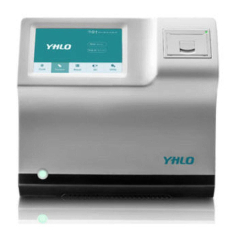
YHLO BIOTECH UNION User manual


©2011-2015 SHENZHEN YHLO BIOTECH CO., LTD. All rights Reserved.
For this Operation Manual, the issue date is 15th April 2015.
Customer service department
Manufacturer:
SHENZHEN YHLO BIOTECH CO.,LTD
Headquarter Address:
13th Floor, Building A1, Kexing Science Park, No.15 Keyuan
Rd., Nanshan District, 518057 Shenzhen, P.R.China
Production Address:
No.5 Building, Lishan Industrial Area, Xinghai Road, Nanshan
District, 518054 Shenzhen, P.R.China
Website:
www.szyhlo.com
E-mail Address:
service@szyhlo.com
Tel:
+86-755-26473359
Fax:
+86-755-26473319
Service Hotline:
+86-400-166-0755
EC -Representative
EC-Representative:
Wellkang Ltd.
Address:
Suite B, 29 Harley Street London, W1G9QR, United Kingdom
Website:
www.CE-marking.eu
E-mail Address:
AuthRep@CE-marking.eu
Tel:
+44 (20)30869438, 32876300
Fax:
+44 (20)76811874

Responsibility on the Manufacturer Party
Contents of this manual are subject to change without prior notice.
All information contained in this manual is believed to be correct. SHENZHEN YHLO BIOTECH
CO., LTD. (hereinafter called YHLO) shall not be liable for errors contained herein or for incidental
or consequential damages in connection with the furnishing, performance, or use of this manual.
YHLO is responsible for the effects on safety, reliability and performance of this product, only if:
a) All installation operations, expansions, changes, modifications and repairs of this product are
conducted by YHLO authorized personnel;
b) The electrical installation of the relevant room complies with the applicable national and local
requirements;
c) The product is used in accordance with the instructions for use.
Note
This equipment must be operated by skilled/trained clinical professionals.
Warning
It is important for the hospital or organization that employs this equipment to carry out a
reasonable service/maintenance plan. Neglect of this may result in machine breakdown or
personal injury.

Warranty
This warranty is exclusive and is in lieu of all other warranties, expressed or implied, including
warranties of merchantability or fitness for any particular purpose.
Exemptions
YHLO's obligation or liability under this warranty does not include any transportation or other
charges or liability for direct, indirect or consequential damages or delay resulting from the
improper use or application of the product or the use of parts or accessories not approved by
YHLO or repair by people other than YHLO authorized personnel.
This warranty shall not extend to:
a) Malfunction or damage caused by improper use or man-made failure.
b) Malfunction or damage caused by unstable or out-of-range power input.
c) Malfunction or damage caused by force majeure such as fire and earthquake.
d) Malfunction or damage caused by improper operation or repair by unqualified or unauthorized
service people.
e) Malfunction of the instrument or part whose serial number is not legible enough.
f) Others not caused by instrument or part itself.
Intellectual Property Statement
SHENZHEN YHLO BIOTECH CO., LTD. owns the intellectual property rights to this YHLO product
and this manual. This manual may refer to information protected by copyright or patents and does
not convey any license under the patent rights or copyright of YHLO, or of others.
YHLO intends to maintain the contents of this manual as confidential information. Disclosure of the
information in this manual in any manner whatsoever without the written permission of YHLO is
strictly forbidden.
Release, amendment, reproduction, distribution, rental, adaptation, translation or any other
derivative work of this manual in any manner whatsoever without the written permission of YHLO
is strictly forbidden.

Preface
UNION Immune Analyzer is designed to perform EIA (Enzyme immunoassay) using dedicated,
single-test (cartridge) and ready to use devices. The fields of application are: autoimmune
antibodies, infectious diseases, hormones, tumor markers, viral antigens and sample types are
using serum, plasma, stool and other biological samples. UNION is designed to be used
exclusively with the reagents and methods established by YHLO that are pre-stored in the memory
of the analyzer, and customer should only use reagents and consumables manufactured by
YHLO.
Any use of generic products may lead to increased risk or measurement errors for which the user
assumes complete responsibility.
Any modification of the software and test procedures in the analyzer’s program will void the
analyzer’s warranty.
For technical support, please contact your local distributor or YHLO support center directly.
Caution Important
Do not use this manual if pages are missing.
To request a new manual, please contact our Customer Service Department.
Screen shots are used for demonstration purposes only.
Shown information may be different in actual use.
Norms applied to this document:
Directive 98/79/EC regarding In-Vitro Diagnostic Medical devices (IVDD)

Personal Safety
Operators must treat all samples as biological hazardous materials and should pay special
cautions during the following operations:
When pipetting samples into the sample well of the cartridge.
When loading cartridges into the carousel.
When removing the cartridges from the carousel.
When handling the waste container.
Operators are suggested to follow the safety guidelines set forth by the Medical Service
Authority in their own region or country and the following protective gears are suggested:
Gloves
Protective Glasses
Lab coats
Electrical Safety
The power cable must be fitted with the right plug corresponding to the wall socket.
The power cable itself must be grounded and should be connected to properly grounded
socket.
The instrument is fitted with protective and safety devices to prevent electrical shocks.
The instrument should not be operated without its casing.
Noise Hazards
The noise generated by the instrument is within international safety limits (<80dB).
Risks due to Liquid Leakage
The instrument is not designed to be waterproof, and liquid damage may occur. Therefore, the
followings must be observed during operation;
Do not place any container with liquid on the instrument.
Avoid soiling the instrument with liquid.
Always remove the buffer/solution tanks from the instrument for refilling
High Temperature Hazards
The reagent strip holder is temperature controlled and its temperature could reach 40°C. Although
the temperature will not cause injury to the operators, a Warning label can be sighted to remind
operators to operate with caution.

Biological Hazard
All patient samples must be treated as biological hazardous material and should be handled with
care. All samples and waste material must be processed following the guidelines set forth by the
Medical ServiceAuthority in their own region or country.
It is mandatory to sanitize the instrument every 7 days using the “Sanitization Program” built into
the instrument software and use Contrad®70 as disinfectant to clean the surface of the
instrument.
Contrad®70 is an emulsion of anionic and nonionic surfactants in an alkaline aqueous base. It
works by soaking, scrubbing, or in ultrasonic cleaning baths.
Safety Symbols
When the following safety symbols are sighted, operate with Caution:
When you see…
Then
Note
Read the statement following the symbol. The statement is
alerting you to information that requires your attention.
Caution
Read the statement following the symbol. The statement is
alerting you to a possibility of system damage.
Warning
Read the statement following the symbol. The statement is
alerting you to an operation hazard that can cause personal
injury.
Important
Read the statement following the symbol. The statement is
alerting you to a possibility of unreliable results.
Biohazard
Read the statement following the symbol. The statement is
alerting you to a potentially biohazardous condition.
Labels Used on the system
The Labels attached to the panels of the system use symbols to clarify the meaning of the text. If
any of the labels peels off, contact our Customer Service Department. The list below shows the
symbols that are used on the analyzer.
Date of Manufacture
Manufacturer

The device is fully in conformance with the Council Directive
Concerning In Vitro Diagnostic Devices 98/79/EC
Biohazard Warning: risk of potentially biohazardous infection
Warning: risk of personal injury or equipment damage
Warning: risk of sharp object
Warning: risk of moving parts
Warning: risk of high temperature
Warning: risk of electrical hazard


Contents
1 System Description...........................................................................................................1
1.1. Hardware introduction............................................................................................2
1.1.1. Analyzing Unit........................................................................................................2
1.1.2. Operation Unit........................................................................................................5
1.1.3. Output Unit.............................................................................................................6
1.2. Software introduction .............................................................................................6
1.2.1 Software Interface..................................................................................................6
1.2.2 Status Bar..............................................................................................................6
1.2.3 Menu Bar ...............................................................................................................7
1.2.4 Information on Main Operation Window .................................................................7
1.3. Cartridges ..............................................................................................................8
2 Installation .......................................................................................................................10
2.1. Unpacking............................................................................................................10
2.2. Installation Requirements..................................................................................... 11
2.2.1 Installation Environment Requirements................................................................ 11
2.2.2 Other requirements for installation ....................................................................... 11
2.3. Installing the Solution Tanks................................................................................. 11
2.3.1 Washing Solution.................................................................................................12
2.3.2 Cleaning solution..................................................................................................13
2.3.3 Sanitizing Solution................................................................................................13
2.4. Waste Disposal....................................................................................................13
2.4.1 Connecting to the Waste Tank.............................................................................14
2.4.2 Connection to a Waste Disposal Drainage...........................................................14
2.5. Electrical Connection ...........................................................................................14
2.6. Connection to the Computer ................................................................................15
3 Operation ......................................................................................................................... 16
3.1 Switch On the Analyzer........................................................................................16
3.2 Getting Started.....................................................................................................16
3.3 Self-check............................................................................................................16
3.4 Procedure for performing a self-check..................................................................17
3.5 Handling Samples................................................................................................18
3.5.1 Calibrator .............................................................................................................18
3.5.2 Quality Control.....................................................................................................19
3.6 Loading and Removing of Cartridges...................................................................20
3.7 Processing...........................................................................................................21
3.8 Identification.........................................................................................................21
3.8.1 Calibration............................................................................................................22

3.8.2 Quality Control.....................................................................................................22
3.8.3 Sample Code Edit................................................................................................22
3.9 Cartridge Code Edit..............................................................................................22
3.10 Methods Update...................................................................................................22
3.11 Run......................................................................................................................24
3.11.1 Common Reagent consumption and Volume Check ............................................24
3.11.2 Pre-Run Check ....................................................................................................25
3.11.3 Duration of Analysis .............................................................................................26
3.12 Stopping the Cycle...............................................................................................26
4. Results and Reports........................................................................................................ 27
4.1 Principle of Analysis .............................................................................................27
4.1.1 Qualitative Tests...................................................................................................27
4.1.2 Quantitative Tests.................................................................................................28
4.2 Units of Measurement..........................................................................................30
4.3 Final Report .........................................................................................................31
5. Maintenance and Troubleshooting................................................................................. 32
5.1 Routine Maintenance ...........................................................................................32
5.2 Periodic Maintenance...........................................................................................32
5.3 Troubleshooting ...................................................................................................33
5.3.1 Start-up Errors .....................................................................................................33
5.3.2 Errors during Operation........................................................................................33
5.3.3 Error Messages....................................................................................................33
6. Appendix.......................................................................................................................... 38
6.1 Operation Accessories .........................................................................................38
6.2 Technical Data .....................................................................................................39
6.3 Requirements for Installation................................................................................40
6.4 Quick Guide for UNION........................................................................................41
6.5 Daily Maintenance Procedure ..............................................................................43
6.6 Configuration of Barcode Scanner .......................................................................45
6.7 Bi-directional Communication...............................................................................46
6.8 Contact information..............................................................................................47

1V2.3.0 OM-UNN valid from 15th April 2015
1System Description
UNION Immune Analyzer is an automated instrument for performing special single tests in Enzyme Immuno
Assay (EIA) format. It is designed to carry out in vitro diagnostic tests in Clinical Laboratories for autoimmune
antibodies, infectious diseases, hormones, tumor markers, viral antigens and sample types are using serum,
plasma, stool and other biological samples. All reagents needed to perform the EIA test are incorporated in a
single ready-to-use reagent cartridge. The whole EIA procedure is performed automatically without the need
for preparation of reagents.
Samples are dispensed manually into the single reagent cartridges by user. All other operation procedures
such as sample dilution, reagent dispensation, washing, and optic reading are executed automatically by the
analyzer. The results can store in the computer database or can be sending to the laboratory information
system (LIS).
Fig.1-1 UNION instrument
This chapter described following three sections:
Hardware Introduction
Software Introduction
Cartridge

V2.3.0 OM-UNN valid from 15th April 2015 2
1.1. Hardware introduction
UNION Immune Analyzer should be connected to a computer with a USB cable.
The Analyzer, where analysis of samples is performed automatically.
A computer. It interfaces with operators and controls the analyzer. It stores all database of analysis
and patient results. It is also capable of bi-directional communication with Laboratory Information
System (LIS). A single computer (operating with Windows®XP SP3 or above) can connect and control
up to 10 units.
Fig.1-2 UNION connection
UNION consists of the analyzing unit, operation unit, output unit, replacing parts and consumables.
1.1.1. Analyzing Unit
Analyzing unit is in modular design with high-performance components purchased around the world.
The analyzing unit consists of the following major parts:
Carousel
Dispensers and Punchers
Washers
Optical System
Solution Tanks

3V2.3.0 OM-UNN valid from 15th April 2015
Fig.1-3 UNION Structure
1.1.1.1. Carousel
The reagent carousel can be rotated freely by hand and up to 30 different cartridges can be loaded for
each analysis cycle. Each position of the tray is numbered in sequence from 1 to 30.
Fig 1-4 UNION Carousel
1.1.1.2. Dispensers and Punchers
The Dispenser and Punchers are coated with high-tech nano ceramic to prevent cross contamination
effectively. The one-stop PCB service and double-needle single motor structure with liquid level sensor
technology are adopted for easy control and replacement.
Solution
Tanks
Washer
Optical
system
Dispensers
Washer
Carousel
Dispensers
and Punchers

V2.3.0 OM-UNN valid from 15th April 2015 4
Fig.1-5 Dispensers and Punchers
1.1.1.3. Washers
The washers adopt the double-placement design with the residual liquid less than 5ul.
Two different washers used for different washing buffers in the same cycle.
Fig. 1-6 Washers

5V2.3.0 OM-UNN valid from 15th April 2015
1.1.1.4. Optical system
The Optical system of UNION includes transmitter and receiver.
Transmitter consists of environment-friendly LED lamps, optical fibers, focus lens.
The wavelengths are of 450 nm and 630 nm in different channels.
Fig. 1-7 Optical Transmitter
1.1.1.5. Solution Tanks
The solution tanks using load cell for performing real-time monitoring of liquid flow.
Fig.1-8 Solution Tanks
1.1.2. Operation Unit
The operation unit is a computer with the operating software of UNION analyzer installed. It manages
running of the analyzing unit, as well as operation and data processing.
Note
PC with Windows®XP SP3 or above system is required for UNION software.

V2.3.0 OM-UNN valid from 15th April 2015 6
1.1.3. Output Unit
The output unit is a printer that prints out the test results and other data.
1.2. Software introduction
Note
In this manual, “click” refers to moving the pointer of the mouse to the desired item and click the left button
of the mouse.
1.2.1 Software Interface
The main window of the operating software is as shown in the figure below.
Fig.1-9 Main interface
1.2.2 Status Bar
The status bar located as Part “A” at the left side of the screen as shown in Fig. 1-9 is referred to as the
instrument(s) status position.
When several analyzers are connected, the status of all the instruments will be displayed by its own icon
button indicating the followings:
Instrument serial number
Error display
Status (Either to be checked, Error or Ready messages will be displayed.)
Click on the specific instrument icon button, the user is directed to the Maine Operation Window of the
specified instrument.

7V2.3.0 OM-UNN valid from 15th April 2015
1.2.3 Menu Bar
The “B” area located at the right side of the screen as shown in Fig. 1-9 displays the Menu Bar.
The following command icon buttons are shown:
WAITING LIST: for Laboratory Information System test request
METHODS: edit the methods of test
CALIBRATIONS: review the records of calibration
QCS: review the records of quality control
RESULTS: review the record of samples and quality control.
OPTIONS: select the language and other functions
QUIT: Exit the operating software
1.2.4 Information on Main Operation Window
Fig.1-10 Main Operation Interface
Clicking on the specific instrument icon button, the Operation Window will appear; the screen is divided into
three main areas:
The right side of the screen indicates the available commands.
The central area displays tables, graphs, warning messages and other information.
The left side of the screen displays the status of the instrument as shown below:
Temperature of the cartridge
Volume of Cleaning solution ( CS )
Volume of Washing Buffer A ( AWB )
Volume of Washing Buffer B ( IWB )

V2.3.0 OM-UNN valid from 15th April 2015 8
The type of Buffer is filled in the AWB fluidic path. ( AWS or CS)
The type of liquid is filled in the IWB fluidic path. ( IWB or CS )
Time to the next Self-Check or if the Self-Check is overdue.
Time to the next Sanitizing cycle or if the Sanitizing cycle is overdue.
Current status of the analyzer (such as ready, running, etc.)
1.3. Cartridges
Each cartridge is supplied with its unique barcode label stuck on its grip (see Fig. 1-11). The barcode is coded
by means of 10 digits (code 128), which consist of the following information:
Test identification code.
Lot number.
Cartridge number.
Expiration date
The 2D barcode is read by the external barcode reader before the analysis cycle starts.
Fig. 1-11 Reagent Kit and Cartridges
Biohazard
The reagent and cartridge potentially have biohazardous condition, please following the standard
operation and safety practices when you use it.
Table of contents
Other YHLO BIOTECH Measuring Instrument manuals