Yingli Solar YL P-35b Series User manual

Yingli Solar PV Modules, Installation and User Manual page 1
This manual applies to photovoltaic modules (“PV modules”,
also commonly known as solar panels) manufactured by
Yingli Green Energy Holding Co., Ltd. (“Yingli Solar”), and
is explicitly written for qualified professionals (“Installer” or
“Installers”), including without limitation licensed electricians
and NABCEP-Certified PV Installers.
INTRODUCTION
Thank you for choosing Yingli Solar as your PV module provider. We appreciate
your business! This manual contains important information pertaining to the
electrical and mechanical installation and maintenance of PV Modules, and
contains safety information that you must read carefully and be familiar with
before handling, installing, and/or maintaining Yingli Solar PV modules.
Yingli Solar does not assume responsibility and expressly disclaims liability for
losses, damages, or expenses arising out of, or in any way connected with this
Installation and User Manual. Yingli Solar assumes no responsibility for any
infringement of patents or other rights of third parties, which may result from
using Yingli Solar PV modules. No license is granted expressly or by implication
or under any patent or patent rights. The information in this manual is believed
to be reliable, but does not constitute an expressed or implied warranty. Yingli
Solar reserves the right to make changes to its PV modules and other products,
their specifications, or this manual without prior notice.
Yingli Solar and its subsidiaries are not liable for any damages caused by
inappropriate installation, use, or maintenance of Yingli Solar PV modules,
including without limitation damages, losses, and expenses caused by non-
observance of the instructions of this manual or caused by or in connection with
products of other manufacturers.
This manual refers to UL certified products and conforms to UL standard 1703:
Flat Plate Photovoltaic Modules and Panels. For PV module installations to be
performed in Canada, the installation shall be in accordance with CSA C22.1,
Safety Standard for Electrical Installations, Canadian Electrical Code, Part 1.
This Installation and User Manual is available in dierent languages. In cases of
discrepancy between versions, the English language version shall control.
Failure to comply with the requirements listed in this manual will invalidate the
Limited Warranty for PV Modules as provided by Yingli Solar at the time of sale
to the direct customer. Additional recommendations are provided to enhance
safety practices and performance results. Please provide a copy of this manual
to the PV system owner for their reference, and inform them of all relevant
aspects of safety, operation, and maintenance.
SAFETY
General
You must understand and follow all applicable local, state, and federal
regulations and standards for building construction, electrical design, fire, and
safety, and must check with local authorities to determine applicable permitting
requirements before attempting to install or maintain PV modules.
Rooftop PV systems should only be installed on dwellings
that have been formally analyzed for structural integrity,
and confirmed to be capable of handling the additional
weighted load of PV system components, including PV
modules, by a certified building specialist or engineer.
For your safety, do not attempt to work on a rooftop until
safety precautions have been identified and taken, including without limitation
fall protection measures, ladders or stairways, and personal protective
equipment (PPE).
For your safety, do not install or handle PV modules under adverse conditions,
including without limitation strong or gusty winds, and wet or frosted roof
surfaces.
The flat-plate PV module construction consists of a laminated assembly of solar
cells encapsulated within an insulating material with a rigid glass surface and
an insulated substrate. The laminated assembly is supported by an aluminum
frame that is also used for mounting the module. See Figure 1 for an illustration
of the PV module components.
Figure 1: Module components and cross-section of the laminated assembly
Electrical
PV modules can produce current and voltage when exposed to light of any
intensity. Electrical current increases with higher light intensity. DC voltage
of 30 Volts or higher is potentially lethal. Contacting the live circuitry of a PV
system operating under light can result in lethal electric
shock.
De-energize PV modules by removing them entirely from
light or by covering their front surface with an opaque
material. Regard the safety regulations for live electrical
equipment when working with modules that are exposed
Junction Box
Cable
Connector
Cell
Frame
1
1. Aluminum Frame
2. Glass
3. Encapsulating EVA
4. PV Cell
5. Backsheet
2
3
5
4
YINGLISOLAR.COM
YINGLI SOLAR PV MODULES
Installation and User Manual
Revision Date Dec 29th, 2015 | Applicable for products rated to 1000 Volts in the United States and Canada | The tenth edition
File name: Corporate Logo with Tagline / Vertical.ai

Yingli Solar PV Modules, Installation and User Manual page 2
to any light. Use Insulated tools and do not wear metallic jewelry while working
with PV modules.
In order to avoid arcing and electrical shock, do not disconnect electrical
connections under load. Faulty connections can also result in arcing and
electrical shock. Keep connectors dry and clean, and ensure that they are in
proper working condition. Never insert metallic objects into the connectors, or
modify them in any way in order to secure an electrical connection.
Do not touch or handle PV modules with broken glass, separated frames or
a damaged backsheet unless the PV modules are first disconnected and you
are wearing proper PPE. Avoid handling PV modules when they are wet unless
cleaning the PV modules as directed in this manual. Never touch electrical
connections that are wet without protecting yourself with insulated gloves.
Transport and Handling
Yingli Solar PV modules must be transported in the supplied packaging only and
kept in the packaging until they are ready to be installed. Protect pallets against
movement and exposure to damage during transportation. Secure pallets from
falling over. Do not exceed the maximum height of pallets to be stacked, as
indicated on the pallet packaging. Store pallets in a cool and dry location until
the PV modules are ready to be unpackaged.
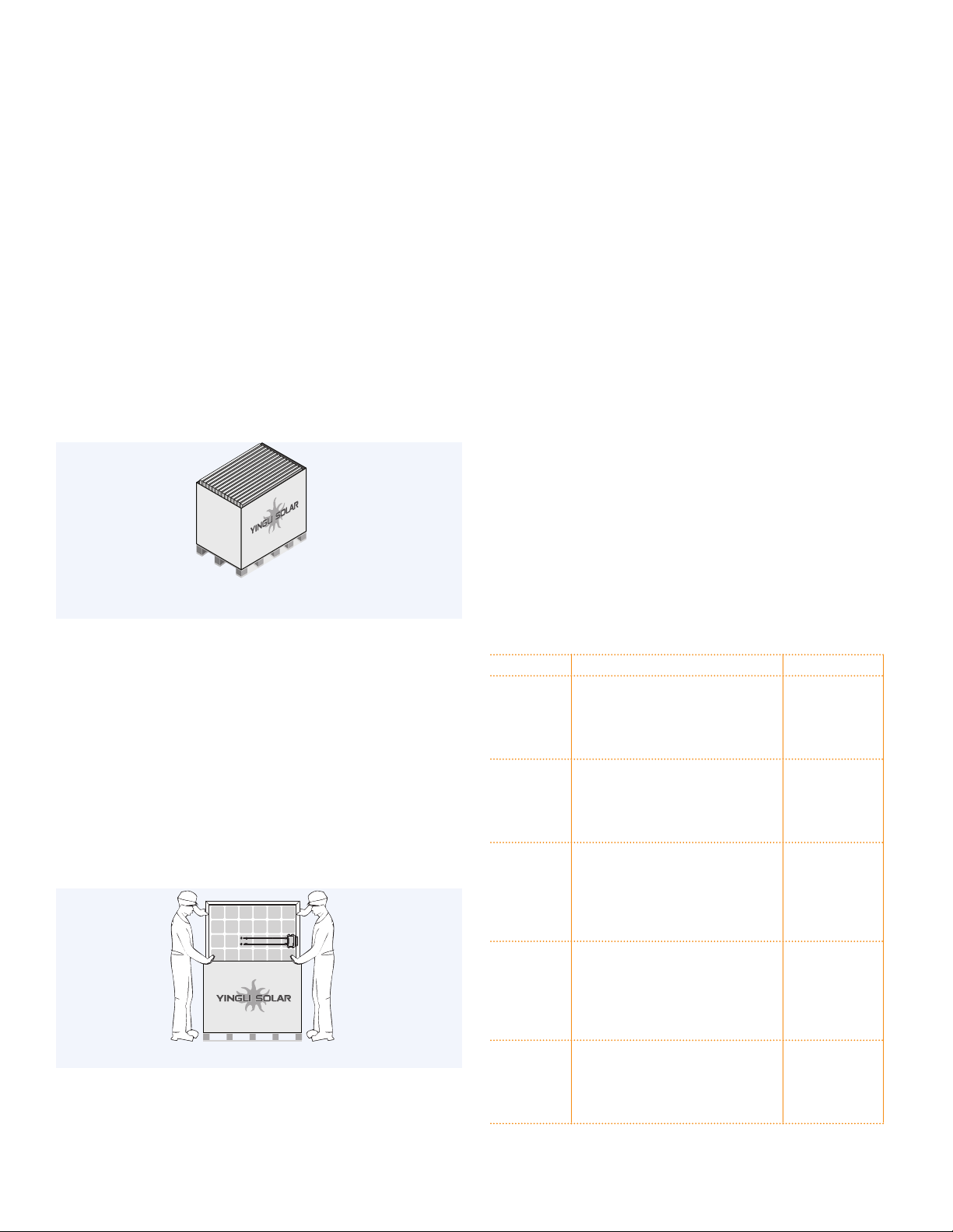
Figure 2: Pallet of PV modules
Yingli Solar PV modules are heavy, and should be handled with care. PV modules
shall be handled at the frame; never use the junction box or cables as a grip. Do
not exert mechanical stress on the cables. Never step on PV modules or drop
or place heavy objects on them. Be careful when placing PV modules on hard
surfaces, and secure them from falling. Broken glass can result in personal injury.
PV modules with broken glass cannot be repaired and must not be used. Broken
or damaged PV modules must be handled carefully and disposed of properly.
For unpacking PV modules from the Yingli Solar supplied packaging, first remove
the pallet lid (after removing securing straps, if provided). Remove PV modules
one at a time by sliding them up the channel in the package (see Figure 3). You
may need to secure the remaining PV modules in the pallet packaging to prevent
them from falling over.
Figure 3: Removing PV modules from a pallet
Check PV modules for damage due to transportation before they are installed;
do not install damaged modules. Contact the company you purchased the Yingli
Solar PV modules from in order to obtain information on making claims for
defective PV modules.
PV module surfaces are susceptible to damage that could aect the performance
or safety of the PV module; do not damage or scratch the PV module surfaces,
and do not apply paint or adhesive to any of the surfaces, including the frame.
For your safety, do not disassemble or modify Yingli Solar PV modules in any
way. Doing so may degrade performance or cause irreparable damage and will
void any applicable warranties.
If it is necessary to store PV modules prior to installation, the PV modules
should remain inside the packaging and protected from exposure that could
compromise the durability of the packaging.
Fire
Yingli Solar PV Modules have a Class C fire resistance rating in accordance
with UL 1703 certification. The fire rating of this PV module is valid only when
mounted in the manner specified in the mechanical mounting instructions.
When PV modules are mounted on rooftops, the roof must have a fire resistant
covering suitable for this application. PV modules are electrical generating
devices that may aect the fire safety of a building.
The use of improper installation methods and/or defective parts may result
in the unexpected occurrence of an electrical arc during operation. In order to
mitigate the risk of fire in this event, PV modules should not be installed near
flammable liquids, gases, or locations with hazardous materials.
In the event of a fire, PV modules may continue to produce a dangerous voltage,
even if they have been disconnected from the inverter, have been partly or
entirely destroyed, or the system wiring has been compromised or destroyed. In
the event of fire, inform the fire crew about the particular hazards from the PV
system, and stay away from all elements of the PV system during and after a fire
until the necessary steps have been taken to make the PV system safe.
A.For cUL listed products - Class C fire rating. For UL listed products -The
modules with the specified construction in below table, when used with a Listed
mounting system that has been rated as a Class A System when installed with
type 1 and/or type 2 modules, is suitable to maintain the System Class A Fire
Rating.
Module model Specific construction Marking
YLxxxP-35b Superstrate: 3.2~4.0 mm thick;
EVA: 0.43~0.5mm thick;
Substrate: 0.309 mm ~ 0.39 mm thick;
Frame: Type” Q243”, ” Q270”, ” Q293”, ”
Q318”, ” Q320”
Module Fire
Performance:
Type 1
YLxxxP-35b Superstrate: 3.2~4.0 mm thick;
EVA: 0.43~0.5mm thick;
Substrate: 0.285 mm ~ 0.295 mm thick;
Frame: Type” Q243”, ” Q270”, ” Q293”, ”
Q318”, ” Q320”
Module Fire
Performance:
Type 2
YLxxxP-29b Superstrate: 3.2~4.0 mm thick;
EVA: 0.43~0.5mm thick;
Substrate: 0.309 mm ~ 0.39 mm thick;
Frame: Type” Q282”, ” Q239”, ” Q241”, ”
Q243”,” Q251B”, ” Q267”, ” Q268”, ” Q291”,
” Q270”
Module Fire
Performance:
Type 1
YLxxxP-29b Superstrate: 3.2~4.0 mm thick;
EVA: 0.43~0.5mm thick;
Substrate: 0.285 mm ~ 0.295 mm thick;
Frame: Type” Q282”, ” Q239”, ” Q241”,
” Q243”, ” Q251B”, ” Q267”, ” Q268”, ”
Q291”, ” Q270”
Module Fire
Performance:
Type 2
YLxxxP-23b Superstrate: 3.2~4.0 mm thick;
EVA: 0.43~0.5mm thick;
Substrate: 0.309 mm ~ 0.39 mm thick;
Frame: Type” Q239”, ” Q241”, ” Q243”, ”
Q267”, ” Q268”, ” Q270”
Module Fire
Performance:
Type 1

Yingli Solar PV Modules, Installation and User Manual page 3
YLxxxP-23b Superstrate: 3.2~4.0 mm thick;
EVA: 0.43~0.5mm thick;
Substrate: 0.285 mm ~ 0.295 mm thick;
Frame: Type” Q239”, ” Q241”, ” Q243”, ”
Q267”, ” Q268”, ” Q270”
Module Fire
Performance:
Type 2
B.The fire rating of the module is valid only when mounted in the manner
specified in the mechanical mounting instructions.
C.The module is considered to be in compliance with UL 1703 only when the
module is mounted in the manner specified by the mounting instructions.
D.A module with exposed conductive parts is considered to be in compliance
with UL 1703 only when it is electrically grounded in accordance with the
instructions and the requirements of the National Electrical Code.
E.Any module without a frame (laminate) shall not be considered to comply
with the requirements of UL 1703 unless the module is mounted with hardware
that has been tested and evaluated with the module under this standard or
by a field Inspection certifying that the installed module complies with the
requirements of UL 1703.
APPLICATION INFORMATION
Application Restrictions
Yingli Solar PV modules must be mounted on appropriate mounting structures
positioned on suitable buildings, the ground, or other structures suitable for PV
modules (e.g. carports, building facades or PV trackers). PV modules must not
be mounted on moving vehicles of any kind. Yingli Solar PV modules must not
be installed in locations where they could be submerged in water.
Yingli Solar PV modules must not be sited in locations where aggressive
substances such as salt or salt-water, or any other type of corrosive agent,
could aect the safety and/or performance of the PV modules. Although Yingli
Solar PV modules have passed the IEC 61701 salt-mist corrosion test with a
salt concentration of 5% by weight, galvanic corrosion can occur between the
aluminum frame of the PV module and mounting or grounding hardware if such
hardware is comprised of dissimilar metals. Yingli Solar recommends that only
stainless steel and aluminum metal directly contact PV modules in seaside
installations to limit corrosion.
Artificially concentrated light must not be directed on Yingli Solar PV modules.
Design Recommendations
Yingli Solar recommends that PV modules be mounted at a minimum tilt angle
of 10 degrees to allow for proper self-cleaning from normal rain showers.
Partial or complete shading of a PV module or modules can significantly reduce
system performance. Yingli Solar recommends minimizing the amount of shade
throughout the year to increase the amount of energy produced by the PV
modules.
Lightning protection is recommended for PV systems that are to be installed in
locations with high probability of lightning strikes.
ELECTRICAL INSTALLATION
Electrical Configuration
Under normal conditions, a photovoltaic module is likely to experience
conditions that produce more current and/or voltage than reported at Standard
Test Conditions (STC: 1000 W/m2, AM 1.5, and 25°C cell temperature). As
required by the US National Electric Code (NEC), the short-circuit current (Isc)
should be multiplied by a factor of 1.25 and the open-circuit voltage (Voc) should
be multiplied by a factor of up to 1.25 based on the lowest ambient temperature
recorded for the installation location when determining component voltage
ratings, conductor current ratings, fuse sizes, and size of controls connected to
the PV output. Follow Section 690.7 in the (NEC) to determine the adjusted
system voltage value.
Refer to Section 690.8 of the NEC for an additional multiplying factor of 125
percent (80 percent de-rating) which may be applicable for sizing fuses and
conductors.
Voltages are additive when PV modules are connected directly in series,
and module currents are additive when PV modules are connected directly
in parallel, as illustrated in Figure 4. PV modules with dierent electrical
characteristics must not be connected directly in series. The use of suitable
third-party electronic devices connected to PV modules may enable dierent
electrical connections and must be installed according to the manufacturer’s
specified instructions.
Figure 4: Electrical diagrams of series and parallel wiring
The maximum number of PV modules that can be connected in a series string
must be calculated in accordance with applicable regulations in such a way
that the specified maximum system voltage of the PV module and all other
electrical DC components will not be exceeded in open-circuit operation at the
lowest temperature expected at the PV system location. In one and two-family
dwellings, PV source circuits and PV output circuits are permitted to have a
maximum system voltage up to 600 volts according to the NEC.
An appropriately rated overcurrent protection device must be used when the
reverse current could exceed the value of the maximum fuse rating of the
module. An overcurrent protection device is required for each series string if
more than two series strings are connected in parallel.
Cables and Wiring
Yingli PV modules are provided with two (2) stranded, sunlight resistant output
cables that are terminated with PV connectors ready for most installations. The
positive (+) terminal has a female connector while the negative (-) terminal
has a male connector. The module wiring is intended for series connections (i.e.
female (+) to male (-) interconnections), but can also be used to connect suitable
third-party electrical devices that may have alternative wiring configurations so
long as the manufacturer’s instructions are followed.
Use field wiring with suitable cross-sectional areas that are approved for use at
the maximum short-circuit current of the PV module. Yingli Solar recommends
installers use only sunlight resistant cables qualified for direct current (DC)
wiring in PV systems. The minimum wire size should be 12 AWG.
Type Wire Size Temperature Rating
Required Minimum Field Wiring USE-2 or PV Wire 12 AWG -40ºC to +90ºC
Table 1: Required minimum field wiring specifications
Cables should be fixed to the mounting structure in such a way that mechanical
Series Wiring (Voltage Additive)
Parallel Wiring (Current Additive)

Yingli Solar PV Modules, Installation and User Manual page 4
damage of the cable and/or the module is avoided. Maintain a minimum cable
bending radius greater or equal than five times the cable diameter. Route
the cable in a way that the tensile stress on the conductor or connections is
prevented. For fixing, use appropriate means, such as sunlight resistant cable
ties and/or wire management clips specifically designed to attach to the PV
module frame. While the cables are sunlight resistant and waterproof, where
possible, avoid direct sunlight exposure and water immersion of the cables.
Connectors
Protect unplugged connectors against moisture, dust
and any environmental pollution. Only clean and dry
plugged connectors fulfill their ingress protection (IP)
class. Ensure that connector caps are hand tight before
connecting the modules. Do not attempt making an
electrical connection with wet, soiled, or otherwise
faulty connectors. Avoid sunlight exposure and water immersion of the
connectors. Avoid connectors resting on the ground or roof surface.
Faulty connections can result in arcs and electrical shock. Check that all electrical
connections are securely fastened. Make sure that all locking connectors are
fully engaged and locked.
Connectors of dierent manufacturers must not be mated. If necessary the
connection of modules can be made by technical personnel after the connector
has been exchanged for one of the same manufacturer. Guarantee and warranty
claims are not aected by a professional exchange.
Figure 5: Series interconnection of a male (-) and female (+) connector
The junction boxes used with Yingli Solar PV modules contain bypass diodes
wired in parallel with the PV cell strings. In the case of partial shading, the
diodes bypass the current generated by the non-shaded cells, thereby limiting
module heating and performance losses. Bypass diodes are not overcurrent
protection devices.
Bypass diodes divert current from the cell strings in the event of partial
shading. See Figure 6 for a diagram showing how the cell strings are electrically
connected with the diodes.
Figure 6: Electrical circuitry of cells and bypass diodes
In the event of a known or suspected diode failure, installers or maintenance
providers should contact the company the PV modules were purchased from.
Never attempt to open the junction box of a Yingli Solar PV module yourself;
replacing diodes inside the junction box is not permitted.
Equipment Grounding
The frame of the PV module, as well as any exposed non-current-carrying metal
parts of fixed equipment that are able to become energized by the PV system,
must be connected to the equipment grounding conductor in order to prevent
electrical shock. Refer to section 250 of the NEC for specific instructions on
grounding. Even when applicable regulations, code requirements, and standards
do not require safety-related grounding, Yingli Solar recommends grounding all
PV module frames in order to ensure the voltage between electrically conductive
equipment and earth ground is zero in all circumstances. A PV module with
exposed conductive parts is considered to be in compliance with UL 1703 only
when it is electrically grounded in accordance with the instructions presented
below and the requirements of the National Electrical Code.
Proper equipment grounding is achieved by bonding all exposed non-current-
carrying metal equipment continuously to one another using an appropriately
sized equipment grounding conductor (EGC) or racking system that can be used
for integrated grounding (see Option C in Grounding Methods below).
Yingli Solar PV modules employ a coated aluminum frame for corrosion
resistance. In order to properly ground the module frame, the coating must be
penetrated.
Grounding wire use copper wire with minimum 12 AWG insulated for a
minimum 90 ºC.
The potential for corrosion due to the electrochemical action between dissimilar
metals in contact is minimized if the electrochemical voltage potential between
the dissimilar metals is low. The grounding method must not result in the direct
contact of dissimilar metals with the aluminum frame of the PV module that
will result in galvanic corrosion. An addendum to UL 1703 recommends metal
combinations not exceed an electrochemical potential dierence of 0.5 Volts.
The frame rails have pre-drilled holes marked with a grounding sign, as
illustrated in Figure 7. These holes should be used for grounding purposes and
must not be used for mounting the PV modules. Do not drill additional holes
into the frame rails.
Where common grounding hardware (nuts, bolts, star washers, spilt-ring lock
washers, flat washers and the like) is used to attach a listed grounding/bonding
device, the attachment must be made in conformance with the grounding
device manufacturer’s instructions.
Figure 7: Grounding hole detail
The following grounding methods are available:
Option A: Grounding Lugs
Manufacturer Part Number Material Tightening Torque
ILSCO GBL-4DBT Tin-plated copper 20 to 25 in-lbf
(2.3 to 2.6 N∙m)
Burndy®CL501-TN Tin-plated copper 20-25 in-lbf
(2.3 to 2.6 N∙m)
Tyco Electronics SolKlip
1954381-4
Nickel and
tin-plated copper
15 +4.4/-1.7 in-lbf
(1.7+0.5/-0.2 N∙m)
Table 2: Grounding lug specifications
Grounding Holes
ø0.236in (6mm)
Fully engage and lock
Cap
+–

Yingli Solar PV Modules, Installation and User Manual page 5
Installation of grounding lugs must be in accordance with the specified
instructions of the respective manufacturers. A grounding lug must be attached
at a designated grounding hole location using #10 stainless steel hardware.
A stainless steel toothed lock washer or KEPS nut is required to adequately
engage the frame and penetrate the nonconductive coating. The screw holding
the appropriately sized EGC in place must firmly clamp the EGC in order to
establish a reliable electrical bond.
Figure 8: Grounding lug detail
Option B: Screw Assembly
1. A grounding screw assembly must be attached at a designated grounding hole
location using only stainless steel hardware. Insert a #10 stainless steel screw
first through the stainless steel cup washer, and then through the grounding
hole.
2. Loosely engage a stainless steel backing nut and toothed lock washer to the
screw.
3. Bend the EGC into an omega (Ω) shape to tightly fit between the partially
installed screw head and cup washer. The EGC shall be exclusively in contact
with stainless steel.
4. Tighten the screw to 35 in-lbf (4 N∙m) torque. The toothed lock washer
should be visibly engaged to the frame.
5. Route the appropriately sized EGC in such a way as to avoid contact with the
aluminum module frame.
Figure 9: Grounding screw assembly detail
Option C: Racking Manufacturer Integrated
Grounding Methods
Yingli Solar PV modules can be grounded by bonding PV modules to a grounded
racking system. Integrated grounding methods must be certified to UL 1703 or
2703 for grounding PV modules and must be installed in accordance with the
specified instructions of their respective manufacturers.
A.Where common grounding hardware (nuts, bolts, star washers, spilt-ring lock
washers, flat washers and the like) is used to attach a listed grounding/bonding
device, the attachment must be made in conformance with the grounding
device manufacturer’s instructions.
B.Common hardware items such as nuts, bolts, star washers, lock washers
and the like have not been evaluated for electrical conductivity or for use
as grounding devices and should be used only for maintaining mechanical
connections and holding electrical grounding devices in the proper position
for electrical conductivity. Such devices, where supplied with the module and
evaluated through the requirements in UL 1703, may be used for grounding
connections in accordance with the instructions provided with the module.
MECHANICAL INSTALLATION
Mounting structures and other mechanical parts must be designed and approved
to withstand the design wind and snow loads applicable for a particular site.
Yingli Solar PV modules must not be subjected to forces from the substructure,
including forces caused by thermal expansion.
The mounting method must not result in the direct contact of dissimilar
metals with the aluminum frame of the PV module that will result
in galvanic corrosion. An addendum to UL 1703 recommends metal
combinations not exceed an electrochemical potential dierence of
0.5 Volts.
Yingli Solar PV modules can be mounted in landscape or portrait orientation, as
illustrated in Figure 10, provided that the mounting method follows one of the
acceptable methods listed below.
Figure 10: Landscape and portrait mounting
In order to maintain the fire class rating, the distance between the PV module
bottom surface and the roof surface shall be at least 2.48 inches (6.3 cm). This
spacing also allows air flow to cool the PV module. Install PV modules with a
minimum spacing of 0.4 inches (1 cm) between neighboring frames to allow for
thermal expansion.
Mounting Methods
The PV module is considered to be in compliance with UL 1703 only when the
PV module is mounted in the manner specified by the mounting instructions PV
module below.
Option A: Bolts or clamps
Refer to the Module Supplement at the end of this manual to determine how
many connection points are required for a specific module series. The locations
of mounting holes and clamp tolerances are illustrated in the drawings located
in the Module Supplement. Do not modify the existing mounting holes or drill
new holes. The minimum tightening force of the following mounting methods
are both 4N.m.
Landscape Orientation
Portrait Orientation
PV Laminate
Backing Nut
Toothed Lock Washer or KEPS Nut
Cup Washer
Aluminum
Frame
Screw
Equipment
Grounding
Conductor
PV Laminate
Backing Nut
Toothed Lock Washer or KEPS Nut
Grounding Lug
Equipment
Grounding
Conductor
Aluminum
Frame
Screw

Yingli Solar PV Modules, Installation and User Manual page 6
• Bolts: Modules must be mounted using the mounting holes located on
the rear side of the long frame parts using ¼ inch stainless steel bolts,
nuts, and washers. Refer to the racking manufacturer for specific torque
requirements. This mounting method has been tested for a maximum
static load of 50 psf (2400 Pa) in both the positive and negative directions.
Figure 11: Detail of a bolt mounting attachment
• Top-down Clamps: Third-party clamps that have been designed for PV
mounting structures are an approved mounting attachment method for Yingli
Solar PV modules. Modules must be fastened using clamps applied to the top
side of the long frame parts. A clamp holds two modules except for the clamps
at the beginning and end of a module row. The centerline of the clamps must
be in line with the mounting hole positions plus or minus a distance of two
(2) inches (50mm). Clamps must be installed according to the manufacturer’s
specified instructions with minimum bolt size of 1/4 inches. Do not apply
excessive pressure on the frame such that the frame deforms. Refer to the
clamp manufacturer for specific hardware and torque requirements. This
mounting method has been tested for a maximum static load of 50 psf (2400
Pa) in both the positive and negative directions.
Figure 12: Detail of a top-down clamp mounting attachment
Only for UL listed products -
A.The System Fire Class Rating of the module or panel in a mounting system in
combination with a roof covering complete with requirements to achieve the
specified System Fire Class Rating for a non-BIPV module or panel.
B.Any module or panel mounting system limitations on inclination required to
maintain a specific System Fire Class Rating.
INSTALLATION OF YGE-Z SERIES
ZEP COMPATIBLE MODULES
Yingli Solar oers the YGE-Z Series PV module which features a modified
aluminum frame that is compatible with mounting and grounding hardware
manufactured by Zep Solar. Refer to the ‘YGE-Z Series Installation Supplement’
for installation information. Detailed design and installation information of Zep
Solar’s mounting systems please find “ YGE-Z Series Installation Supplement”.
The YGE-Z Series PV module warranty will become void if non-Zep-certified
hardware is attached inside the Zep Groove of the module frame.
YGE-Z Series PV modules are also compatible with the mounting and grounding
methods included in this manual.
MAINTENANCE
Yingli Solar recommends that PV systems be periodically inspected by the
installer, or other qualified person.
The purpose of the PV system inspection is to ensure that all system components
are functioning properly. At a minimum, this inspection should confirm the
following:
– All cables and connector attachments are undamaged and properly secured
– No sharp objects are in contact with the PV module surfaces
– PV modules are not shaded by unwanted obstacles and/or foreign material
– Mounting and grounding components are tightly secured with no corrosion
Defects should be addressed immediately.
Cleaning
Over time, dirt and dust can accumulate on the glass surface of the module,
reducing its power output. Yingli Solar recommends periodic cleaning of PV
modules to ensure maximum power output, especially in regions with low
precipitation.
In order to reduce the potential for electrical and thermal shock, Yingli Solar
recommends cleaning PV modules during early morning or late afternoon hours
when solar radiation is low and the modules are cooler, especially in regions
with hotter temperatures.
Never attempt to clean a PV module with broken glass or other signs of exposed
wiring, as this presents a shock hazard.
Clean the glass surface of the PV modules with a soft brush using soft, clean
water with a recommended pressure less than 100psi (690kPa), which is typical
of most municipal water systems. Water with high mineral content may leave
deposits on the glass surface and is not recommended.
Yingli Solar PV modules may contain a hydrophobic anti-reflective coating on
the glass surface to enhance power output and reduce dirt and dust buildup. In
order to avoid module damage, do not clean PV modules with a power washer
or pressure washer. Do not use steam or corrosive chemicals to facilitate the
cleaning of modules. Do not use aggressive tools or abrasive materials that could
scratch or damage the glass surface. Failure to comply with these requirements
may adversely aect the PV module performance.
Yingli Solar PV modules are designed to withstand high snow loads. However, if
removing snow is desired to enhance production, use a brush to gently remove
snow. Do not try to remove frozen snow or ice from PV modules.
DECOMMISSIONING
The dismantling of PV systems must be performed with the same care and
safety precautions used during the initial installation. The PV system can
generate hazardous voltage even after the system has been disconnected.
Follow safety regulations for working with live electrical equipment.
Screw
Backing Nut
Nut Washer
PV Laminate
Mounting Rail
Aluminum Frame
Mounting with bolts diagram
Explode assembly
PV Laminate
Backing Nut
Aluminum Frame
Nut Washer
Support Structure
Screw

Yingli Solar PV Modules, Installation and User Manual page 7
REVISION HISTORY
Date Edition Revision Number
September 1, 2012 The first 2012-Installation Manual_UL_
EN_201209_v01
Auguest 13, 2013 The second 2013-Installation Manual_UL_
EN_201308_v01.1
September 10, 2013 The third 2013-Installation Manual_UL_
EN_201309_v02
October 22, 2013 The forth 2013-Installation Manual_UL_
EN_201310_v02
April 29, 2014 The fifth 2014-Installation Manual_UL_
EN_201404_v02.1
August 6, 2014 The sixth 2014-Installation Manual_UL_
EN_201408_v02.2
March 18, 2015 The seventh 2015-Installation Manual_UL_
EN_201503_v02.3
June 11, 2015 The eighth 2015-Installation Manual_UL_
EN_201506_v03
July 28, 2015 The ninth 2015-Installation Manual_UL_
EN_201507_v03
Dec 29, 2015 The tenth 2015-Installation Manual_UL_
EN_20151229_V03
© Yingli Green Energy Holding Co. Ltd. InstallationManual_UL_EN_20151229_V03
Yingli Green Energy Holding Co., Ltd.
Service hotline:+86-312-2188055
Complaints hotline:+86-312-8922216
YINGLISOLAR.COM

Yingli Solar PV Modules, Installation and User Manual page 8
This supplement refers to modules of the follwing types:
FAMILY YGE 60 Cell SERIES
&
YGE-Z 60 Cell SERIES
YGE 72 Cell SERIES
YGE 72 Cell NH SERIES
PANDA 48 Cell SERIES PANDA 60 Cell SERIES
TYPE
YL230P-29b YL280P-35b YL180C-24b YL225C-30b
YL235P-29b YL285P-35b YL185C-24b YL230C-30b
YL240P-29b YL290P-35b YL190C-24b YL235C-30b
YL245P-29b YL295P-35b YL195C-24b YL240C-30b
YL250P-29b YL300P-35b YL200C-24b YL245C-30b
YL255P-29b YL305P-35b YL205C-24b YL250C-30b
YL260P-29b YL310P-35b YL210C-24b YL255C-30b
YL265P-29b YL315P-35b YL215C-24b YL260C-30b
YL265C-30b
YL270C-30b
MOUNTING REQUIREMENTS
Mounting Method Option A: Bolts or clamps
Modules that Require
Four (4) Connection Points
The Following Modules Require Six (6) Con-
nection Points for Installations that Exceed 50
psf (2400 Pa) Loading
YGE 60 Cell SERIES & YGE-Z 60 Cell
SERIES
YGE 72 Cell NH SERIES
YGE 72 Cell SERIES*
PANDA 60 Cell SERIES & PANDA 60
Cell SERIES
* Connections are required at the four outer mounting holes
ELECTRICAL CHARACTERISTICS
Nameplate ratings are average values. The electrical characteristics are within +/- 10 percent of the indicated values of Isc, Voc, and Pmax under Standard Test
Conditions (irradiance of 1000 W/m2, AM 1.5 spectrum, and a cell temperature of 25ºC). Refer to module datasheets for specific power output tolerance.
Module
family
Module
type
Power
output
Voltage at
Pmax
Current at
Pmax
Open-circuit voltage Short-circuit current Max. DC system
voltage
Max. series fuse
rating
Pmax Vmpp Impp Voc Isc
[W] [V] [A] [V] [A] [V] [A]
YGE 60 Cell
SERIES&YGE-Z 60
Cell SERIES
YL265P-29b 265 30.5 8.70 37.8 9.18 1000 15
YL260P-29b 260 30.3 8.59 37.7 9.09 1000 15
YL255P-29b 255 30.0 8.49 37.7 9.01 1000 15
YL250P-29b 250 29.8 8.39 37.6 8.92 1000 15
YL245P-29b 245 29.6 8.28 37.5 8.83 1000 15
YL240P-29b 240 29.3 8.18 37.5 8.75 1000 15
YL235P-29b 235 29.1 8.08 37.4 8.66 1000 15
YL230P-29b 230 28.9 7.97 37.3 8.57 1000 15
YGE 72 Cell
NH SERIES
YL315P-35b 315 36.8 8.56 45.7 9.12 1000 15
YL310P-35b 310 36.3 8.53 45.6 8.99 1000 15
YL305P-35b 305 36.1 8.45 45.4 8.93 1000 15
YL300P-35b 300 35.8 8.37 45.2 8.86 1000 15
YL295P-35b 295 35.6 8.29 45.0 8.79 1000 15
YL290P-35b 290 35.3 8.22 44.8 8.73 1000 15
YL285P-35b 285 35.0 8.14 44.6 8.66 1000 15
YL280P-35b 280 34.7 8.06 44.4 8.59 1000 15
Module Supplement
YINGLI SOLAR
Installation Method: Zep Solar Mounting Systems
ZSI, ZSII
YGE-Z 60 Cell SERIES*
* Refer to “YGE-Z Series Installation Supplement” for additional information

Yingli Solar PV Modules, Installation and User Manual page 9
PANDA 60 Cell
Series
YL270C-30b 270 30.5 8.85 38.6 9.43 1000 15
YL265C-30b 265 30.1 8.79 38.3 9.37 1000 15
YL260C-30b 260 29.7 8.74 38.1 9.35 1000 15
YL255C-30b 255 29.4 8.68 37.8 9.29 1000 15
YL250C-30b 250 29.1 8.6 37.5 9.14 1000 15
YL245C-30b 245 30.4 8.07 38.1 8.59 1000 15
YL240C-30b 240 30.3 7.93 38.0 8.47 1000 15
YL235C-30b 235 29.9 7.87 37.6 8.41 1000 15
YL230C-30b 230 29.6 7.76 37.0 8.40 1000 15
YL225C-30b 225 29.4 7.66 36.4 8.39 1000 15
PANDA 48 Cell
Series
YL215C-24b 215 24.4 8.81 30.9 9.41 1000 15
YL210C-24b 210 24.2 8.69 30.7 9.34 1000 15
YL205C-24b 205 23.9 8.57 30.5 9.27 1000 15
YL200C-24b 200 23.7 8.44 30.2 9.14 1000 15
YL195C-24b 195 23.4 8.32 30.0 9.00 1000 15
YL190C-24b 190 23.9 7.95 30.1 8.50 1000 15
YL185C-24b 185 23.7 7.81 29.6 8.44 1000 15
YL180C-24b 180 23.5 7.66 29.1 8.41 1000 15

Yingli Solar PV Modules, Installation and User Manual page 10
REAR AND SIDE VIEW DIMENSIONS OF MODULE SERIES
UNITS: INCH (mm)
YGE 60 Cell SERIES YGE 72 Cell SERIES
B
B
B
B
Drainage holes
8–0.12x0.315 (3x8)
Mounting holes
4–0.256x0.315 (6.5x8)
Grounding holes
6–ø0.236 (6)
38.98 (990)
37.24 (946) 1.57 (40)
64.96 (1650)
64.96 (1650)
38.07 (967)
43.31 (1100)
3.94 (100)
2.17 (55)
3.94 (100)
3.94 (100)
A
A
A
A
38.98 (990)
37.24 (946) 1.97 (50)
22.72 (577) 16.02 (408)
77.56 (1970)
22.72 (577)
77.56 (1970)
47.24 (1200)
3.94 (100)
Grounding holes
6–ø0.236 (6)
Mounting holes
6–0.256x0.315 (6.5x8)
Drainage holes
8–0.12x0.315 (3x8)
2.17 (55)
3.94 (100)
27.44 (697)
3.94 (100)
Legend
Legend
Grounding holes
Mounting holes
Drainage holes
Mounting tolerance
YGE 72 Cell YGE 60 Cell
0.47 (12)
1.26 (32)
1.97 (50)
SECTION A–A
Frame Cross Section
0.47 (12)
1.26 (32)
1.57 (40)
SECTION B–B
Frame Cross Section

Yingli Solar PV Modules, Installation and User Manual page 11
REAR AND SIDE VIEW DIMENSIONS OF MODULE SERIES
UNITS: INCH (mm)
PANDA 48 Cell SERIES PANDA 60 Cell SERIES
Legend
Legend
Grounding holes
Mounting holes
Drainage holes
Mounting tolerance
PANDA 48 Cell&PANDA 60 Cell
0.47 (12)
1.57 (40)
1.26 (32)
SECTIONA-A
Frame Cross Section
This manual suits for next models
42
Table of contents
Other Yingli Solar Control Unit manuals
Popular Control Unit manuals by other brands

XQP
XQP 500 Series manual

UTC Fire and Security
UTC Fire and Security interlogix VR1500 Installation & operation instructions

Murphy
Murphy EMS-GC10 Operator's manual

Honeywell
Honeywell ADEMCO 4100SM Installation and setup guide

NEC
NEC NEAX 2400 ICS manual

JYE Tech
JYE Tech FG085 Function Generator Assembly guide