Yingli Solar YLM-J 3.0 PRO Series User manual

YINGLISOLAR.COM © Yingli Energy Development Company Limited
GB Modules Installation and User Manual Page 1
This manual applies to photovoltaic modules (“PV modules”,
also commonly known as solar panels) manufactured by
Yingli Energy Development Company Limited (“Yingli
Solar”), and is explicitly written for qualified professionals
(“Installer” or “Installers”), including without limitation
licensed electricians and RAL Certified PV Installers.
INTRODUCTION
Thank you for choosing Yingli Solar as your PV module provider. We
appreciate your business! This manual contains important information
pertaining to the electrical and mechanical installation and maintenance
of PV modules, and contains safety information that you must read carefully
and be familiar with before handling, installing, and/or maintaining Yingli Solar
PV modules.
Yingli Solar does not assume responsibility and expressly disclaims liability for
losses, damages, or expenses arising out of, or in any way connected with this
Installation and User Manual. Yingli Solar assumes no responsibility for any
infringement of patents or other rights of third parties, which may result from
using Yingli Solar PV modules. No license is granted expressly or by implication
or under any patent or patent rights. The information in this manual is believed
to be reliable, but does not constitute an expressed or implied warranty. Yingli
Solar reserves the right to make changes to its PV modules and other products,
their specifications, or this manual without prior notice.
Yingli Solar and its subsidiaries are not liable for any damages caused by
inappropriate installation, use, or maintenance of Yingli Solar PV modules,
including without limitation damages, losses, and expenses caused by non-
observance of the instructions of this manual or caused by or in connection with
products of other manufacturers.
Yingli Solar PV modules are designed to meet the requirements for the standards
IEC 61215 and IEC 61730, application class A. Modules rated for use in this
application class may be used in systems operating at greater than 50 V DC
or 240 W, where general contact access is anticipated. Modules qualified for
safety through IEC 61730-1 and IEC 61730-2 and within this application class are
considered to meet the requirements for safety class II. In the course of the PV
module certification process, the compliance of this manual with the certification
requirements has been verified by an independent certification laboratory.
This Installation and User Manual is available in dierent languages. In cases of
discrepancy between versions, the English language version shall control.
Failure to comply with the requirements listed in this manual will invalidate the
Limited Warranty for PV Modules as provided by Yingli Solar at the time of sale
to the direct customer. Additional recommendations are provided to enhance
safety practices and performance results. Please provide a copy of this manual
to the PV system owner for their reference, and inform them of all relevant
aspects of safety, operation and maintenance.
SAFETY
General
You must understand and follow all applicable local, state, and federal
regulations and standards for building construction, electrical design, fire, and
safety, and must check with local authorities to determine applicable permitting
requirements before attempting to install or maintain PV modules.
Rooftop PV systems should only be installed on dwellings that have been
formally analyzed for structural integrity, and confirmed to be capable of
handling the additional weighted load of PV system components, including PV
modules, by a certified building specialist or engineer.
For your safety, do not attempt to work on a rooftop until safety
precautions have been identified and taken, including without
limitation fall protection measures, ladders or stairways, and
personal protective equipment (PPE).
For your safety, do not install or handle PV modules under adverse conditions,
includingwithoutlimitationstrongorgustywinds,andwetorfrostedroofsurfaces.
The flat-plate PV module construction consists of a laminated assembly of solar
cells encapsulated within an insulating material with a rigid glass surface and
an insulated substrate. The laminated assembly is supported by an aluminum
frame that is also used for installation the module. See Figure 1 for an illustration
of the PV module components.
Figure 1: Module components and cross-section of the laminated assembly
Electrical
PV modules can produce current and voltage when exposed to
light of any intensity. Electrical current increases with higher
light intensity. DC voltage of 30 Volts or higher is potentially
lethal. Contacting the live circuitry of a PV system operating
under light can result in lethal electric shock.
1
1. Aluminum Frame
2. Glass
3. Encapsulating EVA
4. PV Cell
5. Backsheet
2
3
5
4
YINGLI SOLAR GB MODULES
Installation and User Manual
Revision date: August 10th, 2022 | Applicable for IEC certified products | The second edition

YINGLISOLAR.COM © Yingli Energy Development Company Limited
GB Modules Installation and User Manual Page 2
De-energize PV modules by removing them entirely from light or by covering
their front surface with an opaque material. Regard the safety regulations for
live electrical equipment when working with modules that are exposed to any
light. Use insulated tools and do not wear metallic jewelry while working with
PV modules.
In order to avoid arcing and electrical shock, do not disconnect electrical
connections under load. Faulty connections can also result in arcing and
electrical shock. Keep connectors dry and clean, and ensure that they are in
proper working condition. Never insert metallic objects into the connectors, or
modify them in any way in order to secure an electrical connection.
Do not touch or handle PV modules with broken glass, separated frames or
a damaged backsheet unless the PV modules are first disconnected and you
are wearing proper PPE. Avoid handling PV modules when they are wet unless
cleaning the PV modules as directed in this manual. Never touch electrical
connections that are wet without protecting yourself with insulated gloves.
Transport and Handling
Yingli Solar PV modules must be transported in the supplied packaging only and
kept in the packaging until they are ready to be installed. Protect pallets against
movement and exposure to damage during transportation. Secure pallets from
falling over. Do not exceed the maximum height of pallets to be stacked, as
indicated on the pallet packaging. Store pallets in a cool and dry location until
the PV modules are ready to be unpackaged.
Figure 2: Pallet of PV modules
Yingli Solar PV modules are heavy, and should be handled with care. PV modules
shall be handled at the frame; never use the junction box or cables as a grip. Do
not exert mechanical stress on the cables. Never step on PV modules or drop
or place heavy objects on them. Be careful when placing PV modules on hard
surfaces, and secure them from falling. Broken glass can result in personal injury.
PV modules with broken glass cannot be repaired and must not be used. Broken
or damaged PV modules must be handled carefully and disposed of properly.
For unpacking PV modules from the Yingli Solar supplied packaging, first remove
the pallet lid (after removing securing straps, if provided). Remove PV modules
one at a time by sliding them up the channel in the package (see Figure 3). You
may need to secure the remaining PV modules in the pallet packaging to prevent
them from falling over.
Figure 3: Removing PV modules from a pallet
Check PV modules for damage due to transportation before they are installed;
do not install damaged modules. Contact the company you purchased the Yingli
Solar PV modules from in order to obtain information on making claims for
defective PV modules.
PV module surfaces are susceptible to damage that could aect the performance
or safety of the PV module; do not damage or scratch the PV module surfaces,
and do not apply paint or adhesive to any of the surfaces, including the frame.
For your safety, do not disassemble or modify Yingli Solar PV modules in any
way. Doing so may degrade performance or cause irreparable damage and will
void any applicable warranties.
If it is necessary to store PV modules prior to installation, the PV modules
should remain inside the packaging and protected from exposure that could
compromise the durability of the packaging.
Fire
Yingli Solar PV Modules have a Class C fire resistance rating in accordance with
the IEC 61730-2 certification. When PV modules are mounted on rooftops, the
roof must have a fire resistant covering suitable for this application. PV modules
are electrical generating devices that may aect the fire safety of a building.
The use of improper installation methods and/or defective parts may result
in the unexpected occurrence of an electrical arc during operation. In order to
mitigate the risk of fire in this event, PV modules should not be installed near
flammable liquids, gases, or locations with hazardous materials.
In the event of a fire, PV modules may continue to produce a dangerous voltage,
even if they have been disconnected from the inverter, have been partly or
entirely destroyed, or the system wiring has been compromised or destroyed. In
the event of fire, inform the fire crew about the particular hazards from the PV
system, and stay away from all elements of the PV system during and after a fire
until the necessary steps have been taken to make the PV system safe.
APPLICATION INFORMATION
Application Restrictions
Yingli Solar PV modules must be mounted on appropriate installation structures
positioned on suitable buildings, the ground, or other structures suitable for PV
modules (e.g. carports, building facades or PV trackers). PV modules must not
be mounted on moving vehicles of any kind. Yingli Solar PV modules must not
be installed in locations where they could be submerged in water.
Yingli Solar PV modules must not be sited in locations where aggressive
substances such as salt or salt-water, or any other type of corrosive agent, could
aect the safety and/or performance of the PV modules. Although some types
of Yingli Solar PV modules have passed the IEC 61701 salt-mist corrosion test
with a salt concentration of 5% by weight, galvanic corrosion can occur between
the aluminum frame of the PV module and installation or grounding hardware if
such hardware is comprised of dissimilar metals. Yingli Solar recommends that
only stainless steel and aluminum metal directly contact PV modules in seaside
installations to limit corrosion.
Artificially concentrated light must not be directed on Yingli Solar PV modules.
Design Recommendations
Yingli Solar recommends that PV modules be mounted at a minimum tilt angle
of 10 degrees to allow for proper self-cleaning from normal rain showers.
Partial or complete shading of a PV module or modules can significantly reduce
system performance. Yingli Solar recommends minimizing the amount of shade
throughout the year to increase the amount of energy produced by the PV
modules.
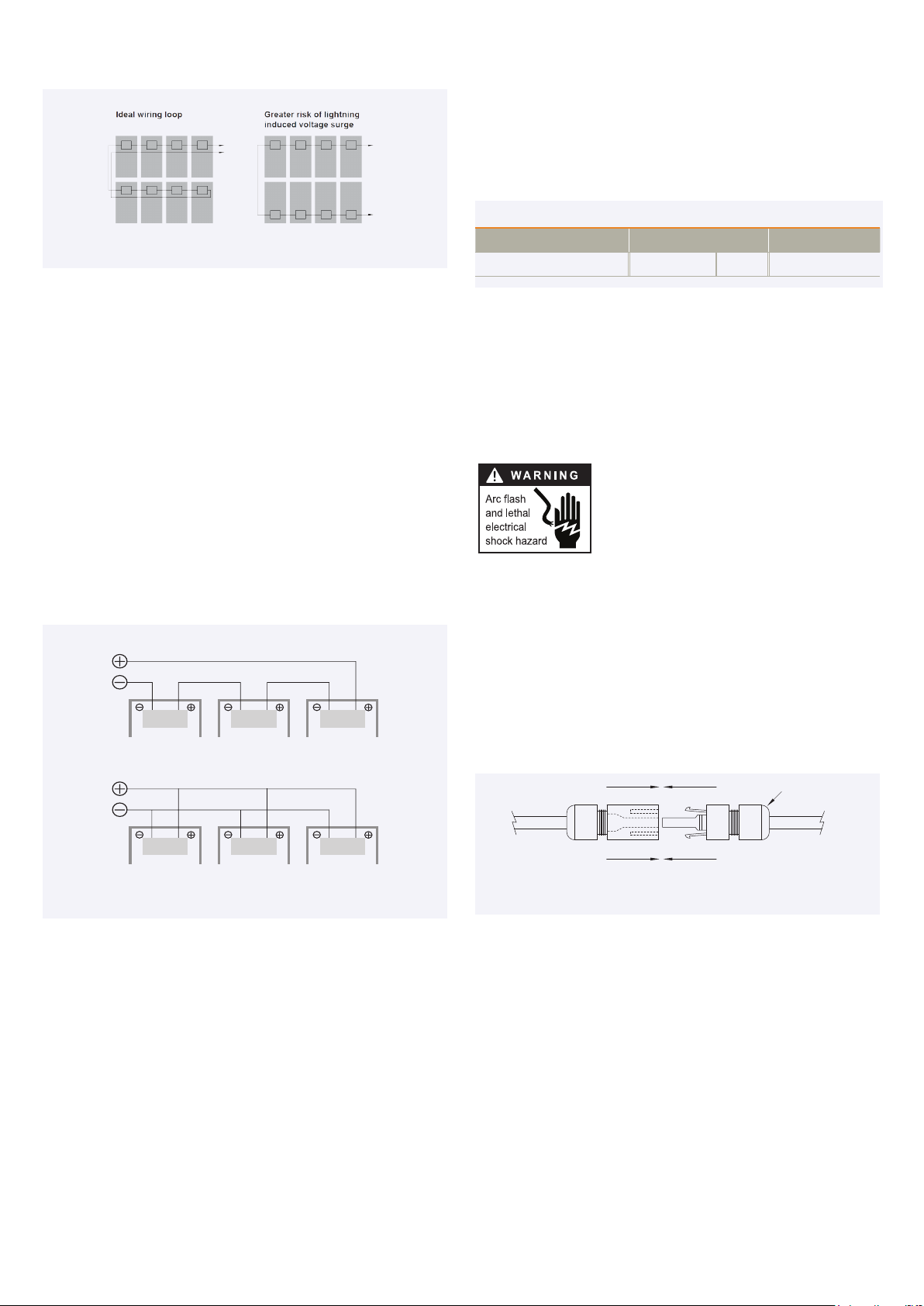
Lightning protection is recommended for PV systems that are to be installed in
locations with high probability of lightning strikes.
High system voltages could be induced in the event of an indirect lightning
strike, which could cause damage to PV system components. The open area of
wire loops should be minimized, as shown in Figure 4, in order to reduce the risk

YINGLISOLAR.COM © Yingli Energy Development Company Limited
GB Modules Installation and User Manual Page 3
Figure 4: Wire loop design recommendation
Series wiring (voltage additive)
Parallel wiring (current additive)
of lightning induced voltage surges.
ELECTRICAL INSTALLATION
Electrical Configuration
Under normal conditions, a photovoltaic module is likely to experience
conditions that produce more current and/or voltage than reported at Standard
Test Conditions (STC: 1000 W/m2, AM 1.5, and 25°C cell temperature). The
short-circuit current (ISC) should be multiplied by a factor of 1.25 and the open-
circuit voltage (VOC) should be multiplied by a factor of up to 1.25 based on
the lowest ambient temperature recorded for the installation location when
determining component voltage ratings, conductor current ratings, fuse sizes,
and size of controls connected to the PV output.
Voltages are additive when PV modules are connected directly in series,
and module currents are additive when PV modules are connected directly
in parallel, as illustrated in Figure 5. PV modules with dierent electrical
characteristics must not be connected directly in series. The use of suitable
third-party electronic devices connected to PV modules may enable dierent
electrical connections and must be installed according to the manufacturer’s
specified instructions.
Figure 5: Electrical diagrams of series and parallel wiring
The maximum number of PV modules that can be connected in a series string
must be calculated in accordance with applicable regulations in such a way that
the specified maximum system voltage of the PV module and all other electrical
DC components will not be exceeded in open-circuit operation at the lowest
temperature expected at the PV system location.
An appropriately rated overcurrent protection device must be used when the
reverse current could exceed the value of the maximum fuse rating of the
module. An over current protection device and anti-reflection diode module
are required for each series string if more than two series strings are connected
in parallel.and reverse polarity is forbidden.
Cables and Wiring
Yingli Solar PV modules are provided with two (2) stranded, sunlight
resistant output cables that are terminated with PV connectors ready for
most installations. The positive (+) terminal has a female connector while the
negative (-) terminal has a male connector. The module wiring is intended for
series connections [i.e. female (+) to male (-) interconnections], but can also be
used to connect suitable third-party electrical devices that may have alternative
wiring configurations so long as the manufacturer’s instructions are followed.
Use field wiring with suitable cross-sectional areas that are approved for use at
the maximum short-circuit current of the PV module. Yingli Solar recommends
installers use only sunlight resistant cables qualified for direct current (DC)
wiring in PV systems. The minimum wire size should be 4mm2.
Table 1: Required minimum field wiring specifications
Testing Standard Wire Size Temperature Rating
Required Minimum Field Wiring EN 50618 4 mm2- 40ºC to + 90ºC
Cables should be fixed to the installation structure in such a way that
mechanical damage of the cable and/or the module is avoided. Do not apply
stress to the cables. Do not bend cables to a bending radius of less than 40mm.
For fixing, use appropriate means, such as sunlight resistant cable ties and/or
wire management clips specifically designed to attach to the PV module frame.
While the cables are sunlight resistant and waterproof, where possible, avoid
direct sunlight exposure and water immersion of the cables.
Connectors
Keep connectors dry and clean, and ensure that
connector caps are hand tight before connecting
the modules. Do not attempt making an electrical
connection with wet, soiled, or otherwise faulty
connectors. Avoid sunlight exposure and water
immersion of the connectors. Avoid connectors resting
on the ground or roof surface.
Faulty connections can result in arcs and electrical shock. Check that all electrical
connections are securely fastened. Make sure that all locking connectors are
fully engaged and locked.
Modules must not be interconnected using connectors from dierent
manufacturers and / or of dierent types. If modules having such dierent
connectors need to be interconnected, a qualified professional may replace
connectors according to the manufacturers’ specified instructions such that an
interconnection can be made with connectors from the same manufacturer and
the same type.
Figure 6: Series interconnection of a male (-) and female (+) connector
Bypass Diodes
The junction boxes used with Yingli Solar PV modules (not Smart Hot Spot Free
module) contain bypass diodes wired in parallel with the PV cell strings. In the
case of partial shading, the diodes bypass the current generated by the non-
shaded cells, thereby limiting module heating and performance losses. Bypass
diodes are not overcurrent protection devices.
Bypass diodes divert current from the cell strings in the event of partial shading.
See Figure 7-1 for a diagram showing how the cell strings are electrically
connected with the diodes.
Every piece of cells from Yingli Smart Hot Spot Free module parallels a diode,
with a cell is covered by shade or occurs an excepion, the paralleled diode can
bypass this cell, thus avoid hot spot, and can retain the maximum power output.
Bypass diodes divert current from a cell in the event of partial shading, See
figure 7-2 for a diagram showing how the cells are electricallly connected with
the diodes.
Fully engage and lock
Cap
+–

YINGLISOLAR.COM © Yingli Energy Development Company Limited
GB Modules Installation and User Manual Page 4
Grounding Holes
Screw
Plain Washers
Spring Washers
Backing Nut
Piercing Washers
Plain Washers
Frame
Grounding Terminal
PV Laminate
Figure 7-1: Electrical circuitry of cell strings and bypass diodes
Figure 7-2: Electrical circuitry of cells and bypass diodes
In the event of a known or suspected diode failure, installers or maintenance
providers should contact the company the PV modules were purchased from.
Never attempt to open the junction box of a Yingli Solar PV module yourself.
PV Array Grounding
For optimal performance, Yingli Solar recommends that the negative pole of the
PV array be connected to ground.
Equipment Grounding
The frame of the PV module, as well as any exposed non-current-carrying metal
parts of fixed equipment that are able to become energized by the PV system,
must be connected to the equipment grounding conductor (EGC) in order to
prevent electrical shock. Even when applicable regulations, code requirements,
and standards do not require safety-related grounding, Yingli Solar recommends
grounding all PV module frames in order to ensure the voltage between
electrically conductive equipment and earth ground is zero in all circumstances.
Proper equipment grounding is achieved by bonding all exposed non-current-
carrying metal equipment continuously to one another using an appropriately
sized EGC or racking system that can be used for integrated grounding (see
Option B in Grounding Methods below).
Yingli Solar PV modules employ a coated aluminum frame for corrosion
resistance. In order to properly ground the module frame, the coating must be
penetrated.
The potential for corrosion due to the electrochemical action between dissimilar
metals in contact is minimized if the electrochemical voltage potential between
the dissimilar metals is low. The grounding method must not result in the direct
contact of dissimilar metals with the aluminum frame of the PV module that
will result in galvanic corrosion. An addendum to UL Standard 1703 “Flat Plate
Photovoltaic Modules and Panels” recommends metal combinations not exceed
an electrochemical potential dierence of 0.5 Volts.
The frame rails have pre-drilled holes marked with a grounding sign, as
illustrated in Figure 8. These holes should be used for grounding purposes and
must not be used for installation the PV modules. Do not drill additional holes
into the frame rails.
Figure 8: Grounding hole detail
The following grounding methods are available:
Option A: Screw Assembly (see Figure 9)
1. The grounding screw must be installed on the designed grounding hole and
must be stainless steel screw.
2. The screw first passes through the stainless steel flat washers. The screw
rods pass through the grounding holes outwards, and then pass through
the stainless steel piercing washers, grounding terminal, stainless steel flat
washers, and stainless steel spring washers in turn, and finally fix them with
stainless steel backing nuts.
3. Tighten the backing nut to a torque of not less than 4 N∙m to ensure that the
backing nut can securely hold the screw.
4. Install piercing washers of appropriate size, and ensure that the protrusions of
the piercing washers reliably pierce the frame of the module.
Figure 9: Grounding screw assembly detail
Option B: Racking Manufacturer Integrated
Grounding Methods
Yingli Solar PV modules can be grounded by bonding PV modules to a grounded
racking system. Integrated grounding methods must be certified for grounding
PV modules and must be installed in accordance with the specified instructions
of their respective manufacturers.
Option C: Additional Third-party Grounding Devices
Yingli Solar PV modules can be grounded using third party grounding devices so
long as they are certified for grounding PV modules and the devices are installed
according to the manufacturer’s specified instructions.
MECHANICAL INSTALLATION
General
Yingli Solar PV Modules have been certified for a maximum static load on the
back of the module of up to 2400 Pa (i.e. wind load) and a maximum static load
on the front of the module of up to either 2400 Pa or 5400 Pa (i.e. wind and
Figure 7-1: Electrical circuitry of cells and bypass diodes

YINGLISOLAR.COM © Yingli Energy Development Company Limited
GB Modules Installation and User Manual Page 5
Landscape Orientation
Portrait Orientation
snow load), depending on the module type (please refer to the data sheet for
this information).
Installation structures and other mechanical parts must be designed and
approved to withstand the design wind and snow loads applicable for a
particular site. Yingli Solar PV modules must not be subjected to forces from the
substructure, including forces caused by thermal expansion.
The installation method must not result in the direct contact of dissimilar
metals with the aluminum frame of the PV module that will result in galvanic
corrosion. An addendum to UL Standard 1703 “Flat Plate Photovoltaic Modules
and Panels” recommends metal combinations not exceed an electrochemical
potential dierence of 0.5 Volts. Yingli Solar PV modules can be mounted in
landscape or portrait orientation, as illustrated in Figure 10, provided that the
installation method follows one of the acceptable methods listed below.
Figure 10: Landscape and portrait installation
In order to maintain the fire class rating, the distance between the PV module
front surface (glass) and the roof surface shall be at least 10 cm. This spacing
also allows air flow to cool the PV module. Install PV modules with a minimum
spacing of 1 cm between neighboring frames to allow for thermal expansion.
Installation Methods
The following installation methods are available:
Bolts or Clamps
Refer to figure 12 and 13. Do not modify the existing installation holes or drill
new holes. Do not apply excessive pressure on the frame such that the frame
deforms.
•Bolts: Modules must be mounted using the installation holes located on the
rear side of the long frame parts using M8 stainless steel bolts, nuts, and
washers. The torque of screw tightening should between 14N∙m to 20N∙m.
Figure 11: Detail of a bolt installation attachment
Figure 12 : Installation rails
The large size modules are mounted with four outer holes, with max mechanical
loads of 5400 Pa snow (front) and 2400 Pa wind (back).
• Top-down Clamps: Third-party clamps that have been designed for PV
installation structures are an approved installation attachment method for
Yingli Solar PV modules. Modules must be fastened using clamps applied to
the top side of the long frame parts. A clamp holds two modules except for the
clamps at the beginning and end of a module row. The module clamps should
not contact with the front glass and deform the frame. and avoiding shadowing
eects from the module clamps. The module frame is not to be modified under
any circumstances. The applied torque value should be big enough to fix the
modules steadily, the torque of screw tightening should between 16 N∙m to
24 N∙m.
Figure 13: Detail of a top-down clamp installation attachment
MAINTENANCE
General
Yingli Solar recommends that PV systems be periodically inspected by the
installer, or other qualified person.
The purpose of the PV system inspection is to ensure that all system components
are functioning properly. At a minimum, this inspection should confirm the
following:
– All cables and connector attachments are undamaged and properly secured
– No sharp objects are in contact with the PV module surfaces
– PV modules are not shaded by unwanted obstacles and/or foreign material
– Installation and grounding components are tightly secured with no corrosion
Defects should be addressed immediately.
Cleaning
Over time, dirt and dust can accumulate on the glass surface of the module,
reducing its power output. Yingli Solar recommends periodic cleaning of PV
modules to ensure maximum power output, especially in regions with low
precipitation.
Screw
Backing Nut
Nut Washer
PV Laminate
Mounting Rail
Aluminum Frame
L L
Inner Four-hole Installation
Long Frame Side Clamp Installation -1
(Clamp Length≥40mm)
L L
L
Outer Four-hole Installation
Long Frame Side Clamp Installation -2
(Clamp Length≥40mm)
Short Frame Side Clamp Installation -2
(Clamp Length≥40mm)
Inner Four-hole installation
Outer Four-hole installation

YINGLISOLAR.COM © Yingli Energy Development Company Limited
GB Modules Installation and User Manual Page 6
Yingli Energy Development Company Limited
Service hotline: +86-312-8922216
YLD_IM_YLM 3.0_GB_EN_V02
In order to reduce the potential for electrical and thermal shock, Yingli Solar
recommends cleaning PV modules during early morning or late afternoon hours
when solar radiation is low and the modules are cooler, especially in regions
with hotter temperatures.
Never attempt to clean a PV module with broken glass or other signs of exposed
wiring, as this presents a shock hazard.
Clean the glass surface of the PV modules with a soft brush using soft, clean
water (PH6-9) with a recommended pressure less than 690kPa, which is
typical of most municipal water systems. Water with high mineral content may
leave deposits on the glass surface and is not recommended.
Yingli Solar PV modules may contain a hydrophobic anti-reflective coating on
the glass surface to enhance power output and reduce dirt and dust buildup. In
order to avoid module damage, do not clean PV modules with a power washer
or pressure washer. Do not use steam or corrosive chemicals to facilitate
the cleaning of modules. Do not use aggressive tools or abrasive materials
that could scratch or damage the glass surface. Failure to comply with these
requirements may adversely aect the PV module performance.
Yingli Solar PV modules are designed to withstand high snow loads. However, if
removing snow is desired to enhance production, use a brush to gently remove
snow. Do not try to remove frozen snow or ice from PV modules.
DECOMMISSIONING
The dismantling of PV systems must be performed with the same care and
safety precautions used during the initial installation. The PV system can
generate hazardous voltage even after the system has been disconnected.
Follow safety regulations for working with live electrical equipment.
RECYCLING
Yingli Solar is a member of PV Cycle, the European association for voluntary
take back and recycling of PV modules. Please contact PV Cycle at www.
pvcycle.org for details regarding the recycling process.
Meaning of crossed –out wheeled dustbin:
Do not dispose of electrical appliances as unsorted municipal waste, use
separate collection facilities.
Contact your local government for information regarding the collection systems
available.
If electrical appliances are disposed of in landfills or dumps, hazardous
substances can leak into the groundwater and get into the food chain, damaging
your health and well-being.
When replacing old appliances with new ones, the retailer is legally obligated to
take back your old appliance for disposals at least free of charge.

YINGLISOLAR.COM © Yingli Energy Development Company Limited
GB Modules Installation and User Manual Page 7
The information in this supplement is believed to be reliable, but does not constitute an expressed or implied warranty. Yingli Solar reserves the right to make
changes to its PV modules and other products, their specifications, or this supplement without prior notice.
This supplement to the installation manual does not contain information about some older module series no longer being manufactured by Yingli Solar. If you
require information about such modules, please contact Yingli Solar.
This supplement refers to modules of the following types:
MODULE TYPES
ELECTRICAL CHARACTERISTICS
Nameplate ratings are average values. The electrical characteristics are within +/- 10 percent of the indicated values of Isc, Voc, and Pmax under Standard Test
Conditions (irradiance of 1000 W/m2, AM 1.5 spectrum, and a cell temperature of 25°C). Refer to module datasheets for specific power output tolerances. Please
refer to Table 1 to see which power classes actually exist for which module series.
Family YLM-J 3.0 PRO
Type YLxxxD-37e 1/2
xxx=390-415
YLxxxD-37e 1500V 1/2
xxx=390-415
YLxxxD-45e 1/2
xxx=475-505
YLxxxD-45e 1500V 1/2
xxx=475-505
YLxxxD-49e 1/2
xxx=515-555
YLxxxD-49e 1500V 1/2
xxx=515-555
Max. system voltage 1000 V 1500 V 1000 V 1500 V 1000 V 1500 V
Family YLM 3.0 PLUS
Type YLxxxD-41f 1/2
xxx=580-605
YLxxxD-41f 1500V 1/2
xxx=580-605
YLxxxD-45f 1/2
xxx=635-670
YLxxxD-45f 1500V 1/2
xxx=635-670
Max. system voltage 1000 V 1500 V 1000 V 1500 V
YINGLI SOLAR GB MODULES
Installation and User Manual Supplement
Revision date: August 10th, 2022 | Applicable for IEC certified products | The second edition

YINGLISOLAR.COM © Yingli Energy Development Company Limited
GB Modules Installation and User Manual Page 8
INSTALLATION METHOD
1. Mounting hole installation (fixed bracket)
Type Mechanical load (Pa) Safety factor Schematic diagram
Purlin perpendicular to
long-side frame
+3600
- 1600 1.5
Purlin parallel to
long-side frame
+1600
- 1600 1.5
Notes:
• To maximize mounting longevity, Yingli Solar strongly recommends the use of corrosion proof (stainless steel) attachment hardware.
• To check whether the surface of the beam is flat and smooth, or add rubber pads on the beam to prevent the module from being crushed when it is pressed down.
• Parts in contact with the modules should use flat stainless steel washers of minimum 1.4 mm thickness with an minimum outer diameter of 15.57 mm.
• Modules can be attached using the mounting holes (2 holes of φ9×14 mm of one long-side frame, ≥1300 mm spacing) on the back of the module frame, by fixing the module to the
support rails with bolts.
• Secure the module in each mounting location with M8 bolts and matching flat washers, spring washers and nuts, and tighten to a torque of 14~20 N∙m. The tightening steps as follows:
use torque wrench to tighten nut to target torque, nut loosen 90~180 degrees, finally tighten the nut to the target torque and reduce the torque attenuation.
2. Mounting hole installation (1P tracker)
Type Mechanical load (Pa) Safety factor Schematic diagram
Purlin parallel to
long-side frame
+1600
- 1600 1.5
Notes:
• To maximize mounting longevity, Yingli Solar strongly recommends the use of corrosion proof (stainless steel) attachment hardware.
• Parts in contact with the modules should use flat stainless steel washers of minimum 1.4 mm thickness with an minimum outer diameter of 15.57 mm.
• Modules can be attached using the mounting holes (2 holes of φ7×10 mm of one long-side frame, 400 mm spacing for special tracker, or 2 holes of φ9×14 mm of one long-side frame,
spacing ≥L/3, L represents the length of the long side of the module) on the back of the module frame, by fixing the module to the support rails with bolts.
• Secure the module in each mounting location with 2 M6 bolts or 2 M8 bolts, and matching flat washers, spring washers and nuts, and tighten to a torque of 14~20 N∙m. The tightening
steps as follows: use torque wrench to tighten nut to target torque, nut loosen 90~180 degrees, finally tighten the nut to the target torque and reduce the torque attenuation.

YINGLISOLAR.COM © Yingli Energy Development Company Limited
GB Modules Installation and User Manual Page 9
3. Mounting hole installation (2P tracker)
Type Mechanical load (Pa) Safety factor Schematic diagram
Purlin parallel to
long-side frame
+1600
- 1600 1.5
Notes:
• To maximize mounting longevity, Yingli Solar strongly recommends the use of corrosion proof (stainless steel) attachment hardware.
• Parts in contact with the modules should use flat stainless steel washers of minimum 1.4 mm thickness with an minimum outer diameter of 15.57 mm.
• Modules can be attached using the mounting holes (the number of mounting holes used for a single long-side frame ≥2, including at least one φ7×10 mm hole) on the back of the
module frame, by fixing the module to the support rails with bolts.
• Secure the module in each mounting location with M6 and M8 bolts, and matching flat washers, spring washers and nuts, and tighten to a torque of 14~20 N∙m. The tightening steps as
follows: use torque wrench to tighten nut to target torque, nut loosen 90~180 degrees, finally tighten the nut to the target torque and reduce the torque attenuation.

YINGLISOLAR.COM © Yingli Energy Development Company Limited
GB Modules Installation and User Manual Page 10
4. Clamp installation
Type Mechanical load (Pa) Safety factor Schematic diagram
Purlin perpendicular to
long-side frame
+3600
- 1600 1.5
Purlin parallel to
long-side frame
+1600
- 1600 1.5
Notes:
• To maximize mounting longevity, Yingli Solar strongly recommends the use of corrosion proof (stainless steel) attachment hardware.
• To check whether the surface of the beam is flat and smooth, or add rubber pads on the beam to prevent the module from being crushed when it is pressed down.
• L represents the length of the long side of the module, the described distances are from the module edge to the middle of the clamp.
• The long-side frames of the module are fixed to the mounting beam or rail by at least 4 clamps that can be fitted with M8 bolts.
• The length of the clamp ≥40 mm, and the module frame to maintain at least 7 mm but not more than 10 mm overlap part, could not contact with the front glass, shall not make the
frame deformation, and should avoid the shading eect of the clamp.
• Tighten M8 bolts to a torque of 14~20 N∙m. The tightening steps as follows: use torque wrench to tighten nut to target torque, nut loosen 90~180 degrees, finally tighten the nut to the
target torque and reduce the torque attenuation.

YINGLISOLAR.COM © Yingli Energy Development Company Limited
GB Modules Installation and User Manual Page 11
80°~87°
TRANSFER REQUIREMENTS UNPACKING INSTRUCTIONS
It is strictly forbidden for people to stand on both sides of the forklift during the
operation, and there is a risk of the box falling over and causing injury to people
if the operation speed is too fast, and the stacking of boxes is strictly forbidden.
When lifting, need to use lifting tools with sucient tension to ensure that the
center of gravity of the box is stable and to make suitable support structures on the
top of the package, such as wooden boards with the same length and width as the
package, to ensure that the top of the modules is not squeezed.
Before unpacking, please check whether the product serial number and information
on the external box are correct, read the unpacking instructions carefully, prohibit
the use of customized unpacking methods, prohibit violent removal to avoid
scratching the modules, please refer to the recommended unpacking steps and
tools. Unpacking work must be operated by 2 or more people, wear cut-proof
insulated gloves, and other labor protection requirements of PV plant construction
specifications need to be met.
Unpacking must be done with anti-tilting brackets, please contact your customer
manager for the specific requirements of the anti-tilting bracket.
2. Safety ropes are required to secure the modules to the forklift with a tensile
strength greater than 2000 kgf.
2. Pass the forearm of the anti-tilting bracket through the pallet, insert the two
bolts into the front round hole of the anti-tilting bracket, and adjust the support
angle of the anti-tilting bracket so that the angle with the ground is between 80°
and 87°.
3. When placing it, need to wait for the packing box to be stable before untying
the safety rope.
4. Make sure the pallet is separated from the forks and then exit slowly.
Notes:
- Fork length needs to be more than 1.1 m, gantry height needs to be more than 1.7
m and width more than 1.5 m, gantry can withstand more than 1.5 tons pressure.
- The top of the gantry needs to be placed with cushioning material.
- These transfer requirements apply to upright packaging modules.
Note:
- These unpacking instructions apply to upright packaging modules.
1. Forks enter in the direction of the long side of the pallet, close to the pallet and
prohibit slamming against the modules.
1. Place the package on the flat working ground, cut the packing belts and remove
the wooden brackets.
3. Remove the packing belts and carton (the cardboard on one side of the anti-
tilting bracket can be retained), leaving only 1 or 2 internal belts, then carefully
push the modules so that they rest diagonally against the anti-tilting bracket.
4. Two people work together to carry the modules one by one, if there are any left
over, secure the remaining modules to the anti-tilting bracket with tie-downs or
place them flat on a pallet (no more than 20 pieces per pallet).
This manual suits for next models
1
Table of contents
Other Yingli Solar Control Unit manuals
Popular Control Unit manuals by other brands

XQP
XQP 500 Series manual

UTC Fire and Security
UTC Fire and Security interlogix VR1500 Installation & operation instructions

Murphy
Murphy EMS-GC10 Operator's manual

Honeywell
Honeywell ADEMCO 4100SM Installation and setup guide

NEC
NEC NEAX 2400 ICS manual

JYE Tech
JYE Tech FG085 Function Generator Assembly guide