manuals.online logo
Brands
  1. Home
  2. •
  3. Brands
  4. •
  5. YOKOGAWA
  6. •
  7. Media Converter
  8. •
  9. YOKOGAWA JUXTA PF1 User manual

YOKOGAWA JUXTA PF1 User manual

User’s
Manual
1
Thank you for purchasing the JUXTA Signal Conditioner.
Please read through this manual before use for correct handling.
2-9-32, Naka-cho Musashino-shi, Tokyo 180-8750 Japan
Phone: +81-422-52-7179 Facsimile: +81-422-52-6793
http://www.yokogawa.com/ns/juxta/
You can download the latest manuals from the following website:
IM 77J10P01-01EN
1st Edition Feb. 2021 (YK)
CAUTIONARY NOTES FOR SAFE USE OF THE
PRODUCT
This User’s Manual should be carefully read before installing and
operating the product. Please keep this User’s Manual for future
reference.
The related manuals and general specications are shown in the
table below.
Doc. Name Doc. Number
PH10 Electrical to Pneumatic Converter
(User’s Manual)
IM 77J10P01-01EN
(This manual)
PH10 Electrical to Pneumatic Converter
(General Specications)
GS 77J10P01-01EN
User’s manuals in the above table are essential parts of the
product; keep it in a safe place for future reference.
This manual is intended for the following personnel;
• Engineers responsible for installation, wiring, and maintenance
of the equipment.
• Personnel responsible for normal daily operation of the
equipment.
The following symbol is used on the product and in this manual to
ensure safe usage.
WARNING
Calls attention to actions or conditions that could
cause serious or fatal injury to the user, and indicates
precautions that should be taken to prevent such
occurrences.
CAUTION
Calls attention to actions or conditions that could
cause injury to the user or damage to the instrument
or property and indicates precautions that should be
taken to prevent such occurrences.
QR Code
The product has a QR Code pasted for e󰀩cient plant
maintenance work and asset information management.
It enables conrming the specications of purchased products
and user’s manuals.
For more details, please refer to the following URL.
https://www.yokogawa.com/qr-code
* QR Code is a registered trademark of DENSO WAVE
INCORPORATED.
CHECKING PRODUCT SPECIFICATIONS
AND PACKAGE
(1) Checking the Model and Product Specications
Check that the model and specications indicated on the
nameplate attached to the main unit are as ordered.
(2) Packaged Items
Check that the package contains the following items:
• PF1: 1 unit
Standard Accessories:
• Tag number label: 1 sheet
• Terminal cover: 2 pieces
• User’s manual (IM 77J10P01-01EN, this manual): 1 copy
GENERAL
This plug-in type Pneumatic to Electrical Converter inputs 20 to
100 kPa, 0.2 to 1.0 kgf/cm2or 3 to 15 psi air pressure signal and
converts it into various DC current or voltage signal.
• Compact and high performance by using a semiconductor
pressure sensor.
• No positional error.
• With automatic sealing function.
MODEL AND SUFFIX CODES
Model Su󰀩x codes Description
PF1 -xx-1 *B Pneumatic to Electrical Converter
Input
signal
-1 0.2 to 1.0 kgf/cm2
-2 3 to 15 psi
-3 20 to 100 kPa
Output signal
A4 to 20 mA DC
B2 to 10 mA DC
C1 to 5 mA DC
D0 to 20 mA DC
E0 to 16 mA DC
F0 to 10 mA DC
G0 to 1 mA DC
10 to 10 mV DC
20 to 100 mV DC
30 to 1 V DC
40 to 10 V DC
50 to 5 V DC
61 to 5 V DC
7−10 to +10 V DC
ZCustom order (DC current/voltage signal)
Power supply -1 24V DC±10%
Style code *B Style B
Model PF1
Pneumatic to Electrical
Converter
2IM 77J10P01-01EN 1st Edition
1. MOUNTING METHOD
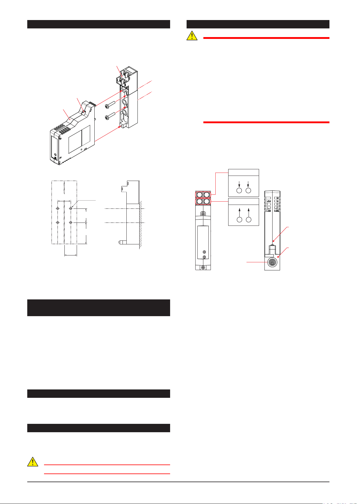
First, Fix the terminal board to the wall as shown in the gure
below (*). Then x the main body on terminal board with two
screws.
* Terminal board can be detached from the main body by
removing two screws.
Main body
Mounting screws
(upper and lower)
Terminal board
Mounting dimensions (Unit: mm)
24
M4 screw
43
27
25.5
The PF1 can be mounted on the Air Supply Unit (PPU) and
can be mixed mounting with the PH10 (Electrical to Pneumatic
Converter).
The mounting method is the same as PH10. Refer to the PH10
user’s manual.
• Document number: IM 77J10P10-01EN
2. INSTALLATION AND ENVIRONMENTAL
CONDITIONS
• Avoid the following environments for installation locations:
Areas with vibrations, corrosive gases, dust, water, oil,
solvents, direct sunlight, radiation, a strong electric eld,
and/or a strong magnetic eld, direct radiant heat, wind,
temperature uctuation.
• If there is any risk of a surge being induced into the power line
and/or signal lines due to lightning or other factors, a dedicated
lightning arrester should be used as protection for both the
product and a eld-installed device.
• Use indoors at an altitude of 2000 m or less.
• Operating temperature/humidity range: 0 to 50°C/5 to 90%RH
(no condensation)
3. AUTOMATIC SEALING
When main body of the PF1 is removed from the terminal board,
air will be sealed automatically by closing a valve of terminal
board.
4. PIPING
Connect pipe for input pneumatic signal to inlet (Rc 1/4 (PT 1/4
female thread)) of terminal board. The thread size for pipes is R
1/4 (PT 1/4 male thread).
CAUTION
Fastening torque of pipe is 2±0.5 N•m
5. EXTERNAL WIRING
WARNING
●To avoid the risk of an electric shock, turn o󰀨 the
power supply and use a tester or similar device to
ensure that no power is supplied to a cable to be
connected, before carrying out wiring work.
●Do not operate the product in the presence of
ammable or explosive gases or vapors. To do so is
highly dangerous.
●Use of the product ignoring the specications may
cause overheating or damage. Before turning on
the power, ensure the following:
•Power supply voltage and input signal value
applied to the product should meet the required
specications.
•The external wiring to the terminals and wiring to
ground are as specications.
Wiring should be connected to the terminals on the socket of the
product. The terminals for external connections are of M3 screws.
Use crimp-on terminal lugs for connections to the terminals.
• Recommended cables: A nominal cross-sectional area of
0.5 mm2or thicker for signal cables, and that of 1.25 mm2or
thicker for power cables.
Wiring Diagram
PF1
bottom view
1 2
3 4
+ –
34
Power supply
+
24 V DC
–
1 2
Output signal
Input signal
(Air pressure piping
inlet)
PF1
Main body
Terminal
board
3IM 77J10P01-01EN 1st Edition
6. MAINTENANCE
The product starts running immediately when the power is turned
on; however, it needs 10 to 15 minutes of warm-up before it
meets the specied performance.
6.1 Calibration Apparatus
• A Pneumatic Pressure Standard (YOKOGAWA MC100 or the
equivalent)
• A DC Voltage/Current Source (YOKOGAWA GS200 or the
equivalent)
6.2 Calibration Procedure
1. Connect the instruments as shown below.
Power supply
PF1
bottom view
+
24 V DC
–
1
1
2
3 4
2
Input signal
Output signal
Zero-adjustment volume
Span-adjustment volume
Pneumatic
Pressure
Standard
PF1
Main body
Terminal
block
DMM
+–
3 4
R
R: 250 Ω precision resistor
for current output
2. Use the pneumatic pressure standard and apply input signals
equivalent to 0, 25, 50, 75, and 100% of the input span to the
product.
3. Check to see the corresponding output voltages are 0, 25, 50,
75, and 100% respectively and within the specied accuracy
rating.
• If the output signals are out of the accuracy rating range,
adjust the output signal level using the zero and span
adjustment volumes on front face of the product.
Blank Page

Other YOKOGAWA Media Converter manuals

YOKOGAWA JUXTA MG1 PT User manual

YOKOGAWA

YOKOGAWA JUXTA MG1 PT User manual

YOKOGAWA ISC450G User manual

YOKOGAWA

YOKOGAWA ISC450G User manual

YOKOGAWA DO400 User manual

YOKOGAWA

YOKOGAWA DO400 User manual

YOKOGAWA JUXTA VJP8 Series User manual

YOKOGAWA

YOKOGAWA JUXTA VJP8 Series User manual

YOKOGAWA SC402G User manual

YOKOGAWA

YOKOGAWA SC402G User manual

YOKOGAWA YewSeries 80 STED Style S User manual

YOKOGAWA

YOKOGAWA YewSeries 80 STED Style S User manual

YOKOGAWA FLXA402 User manual

YOKOGAWA

YOKOGAWA FLXA402 User manual

YOKOGAWA JUXTA VJB1 User manual

YOKOGAWA

YOKOGAWA JUXTA VJB1 User manual

YOKOGAWA FLXA402 Manual

YOKOGAWA

YOKOGAWA FLXA402 Manual

YOKOGAWA Vitesse FA-M3V User manual

YOKOGAWA

YOKOGAWA Vitesse FA-M3V User manual

YOKOGAWA JUXTA MB1 User manual

YOKOGAWA

YOKOGAWA JUXTA MB1 User manual

YOKOGAWA VJX7 User manual

YOKOGAWA

YOKOGAWA VJX7 User manual

YOKOGAWA Juxta VJU7 User manual

YOKOGAWA

YOKOGAWA Juxta VJU7 User manual

YOKOGAWA FLXA402 User manual

YOKOGAWA

YOKOGAWA FLXA402 User manual

YOKOGAWA JUXTA VJR6 User manual

YOKOGAWA

YOKOGAWA JUXTA VJR6 User manual

YOKOGAWA VigilantPlant PK200 User manual

YOKOGAWA

YOKOGAWA VigilantPlant PK200 User manual

YOKOGAWA EXA DO402G User manual

YOKOGAWA

YOKOGAWA EXA DO402G User manual

YOKOGAWA JUXTA VJD1 User manual

YOKOGAWA

YOKOGAWA JUXTA VJD1 User manual

YOKOGAWA Admag SE14 User manual

YOKOGAWA

YOKOGAWA Admag SE14 User manual

YOKOGAWA PH450G Manual

YOKOGAWA

YOKOGAWA PH450G Manual

YOKOGAWA EXA DO402G User manual

YOKOGAWA

YOKOGAWA EXA DO402G User manual

YOKOGAWA JUXTA VJH7 User manual

YOKOGAWA

YOKOGAWA JUXTA VJH7 User manual

YOKOGAWA YFGW610 User manual

YOKOGAWA

YOKOGAWA YFGW610 User manual

YOKOGAWA JUXTA VJQ8 Series User manual

YOKOGAWA

YOKOGAWA JUXTA VJQ8 Series User manual

Popular Media Converter manuals by other brands

ATC LIFESTYLE 1000 user manual

ATC

ATC LIFESTYLE 1000 user manual

Humandata USB-301 user manual

Humandata

Humandata USB-301 user manual

Lika Linepuls SME12 Series Mounting instructions

Lika

Lika Linepuls SME12 Series Mounting instructions

Matrox Monarch EDGE Device Set Up

Matrox

Matrox Monarch EDGE Device Set Up

Philips MCM2250 Mounting instructions

Philips

Philips MCM2250 Mounting instructions

Lindy LDAC-Duo user manual

Lindy

Lindy LDAC-Duo user manual

BYONICS TinyTrak3 owner's manual

BYONICS

BYONICS TinyTrak3 owner's manual

Sony DVMC-DA2 Service manual

Sony

Sony DVMC-DA2 Service manual

Denver MC-5300 user manual

Denver

Denver MC-5300 user manual

TRENDnet TU-PS2 Specifications

TRENDnet

TRENDnet TU-PS2 Specifications

MuxLab 500021 Installation instructions manual

MuxLab

MuxLab 500021 Installation instructions manual

NetUP Streamer HD v3 8-24x user manual

NetUP

NetUP Streamer HD v3 8-24x user manual

Bose Wave music system owner's guide

Bose

Bose Wave music system owner's guide

Philips Streamium WAK3300/12 user manual

Philips

Philips Streamium WAK3300/12 user manual

weha LS-001 Operating instructions and parts manual

weha

weha LS-001 Operating instructions and parts manual

Fagor HTT 103 user manual

Fagor

Fagor HTT 103 user manual

Merging Anubis Appendix

Merging

Merging Anubis Appendix

Violet Audio ADP61 user manual

Violet Audio

Violet Audio ADP61 user manual

manuals.online logo
manuals.online logoBrands
  • About & Mission
  • Contact us
  • Privacy Policy
  • Terms and Conditions

Copyright 2025 Manuals.Online. All Rights Reserved.