manuals.online logo
Brands
  1. Home
  2. •
  3. Brands
  4. •
  5. YOKOGAWA
  6. •
  7. Media Converter
  8. •
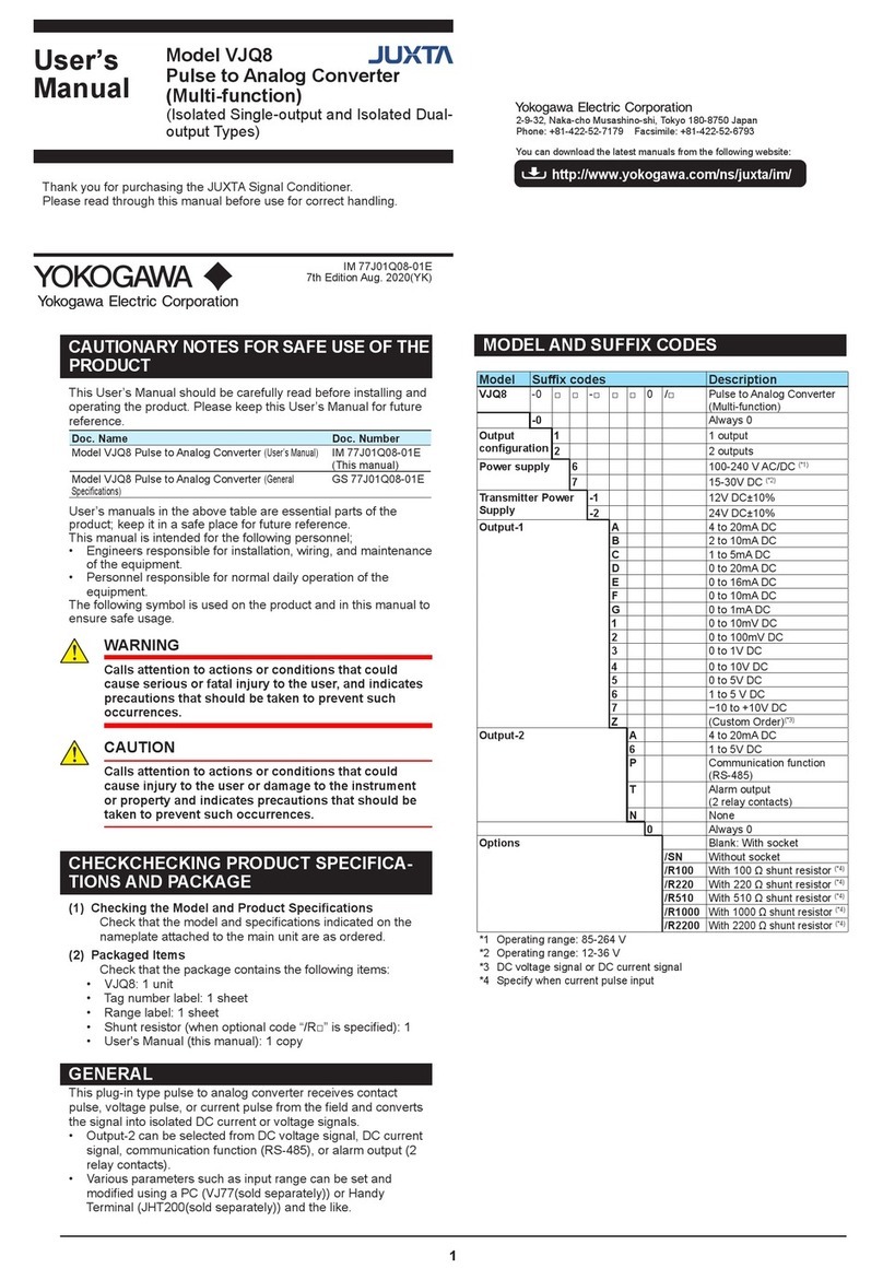
  9. YOKOGAWA JUXTA VJD1 User manual

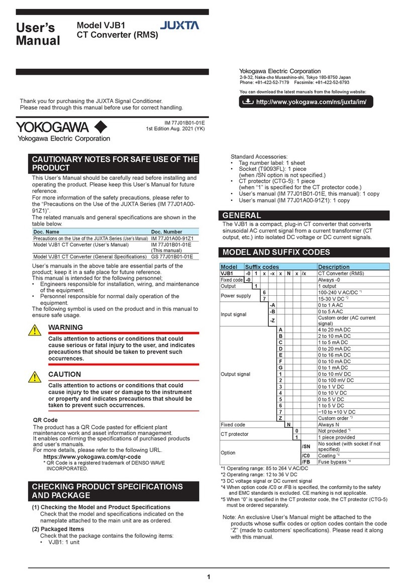
YOKOGAWA JUXTA VJD1 User manual

User’s
Manual
1
Thank you for purchasing the JUXTA Signal Conditioner.
Please read through this manual before use for correct handling.
2-9-32, Naka-cho Musashino-shi, Tokyo 180-8750 Japan
Phone: +81-422-52-7179 Facsimile: +81-422-52-6793
http://www.yokogawa.com/ns/juxta/im/
You can download the latest manuals from the following website:
IM 77J01D01-01E
1st Edition Aug. 2021 (YK)
CAUTIONARY NOTES FOR SAFE USE OF THE
PRODUCT
This User’s Manual should be carefully read before installing and
operating the product. Please keep this User’s Manual for future
reference.
For more information of the safety precautions, please refer to
the “Precautions on the Use of the JUXTA Series (IM 77J01A00-
91Z1)”.
The related manuals and general specications are shown in the
table below.
Doc. Name Doc. Number
Precautions on the Use of the JUXTA Series
(User’s Manual)
IM 77J01A00-91Z1
Model VJD1 Tachogenerator Converter
(User’s Manual)
IM 77J01D01-01E
(This manual)
Model VJD1 Tachogenerator Converter
(General Specications)
GS 77J01D01-01E
User’s manuals in the above table are essential parts of the
product; keep it in a safe place for future reference.
This manual is intended for the following personnel;
• Engineers responsible for installation, wiring, and maintenance
of the equipment.
• Personnel responsible for normal daily operation of the
equipment.
The following symbol is used on the product and in this manual to
ensure safe usage.
WARNING
Calls attention to actions or conditions that could
cause serious or fatal injury to the user, and indicates
precautions that should be taken to prevent such
occurrences.
CAUTION
Calls attention to actions or conditions that could
cause injury to the user or damage to the instrument
or property and indicates precautions that should be
taken to prevent such occurrences.
QR Code
The product has a QR Code pasted for e󰀩cient plant
maintenance work and asset information management.
It enables conrming the specications of purchased products
and user’s manuals.
For more details, please refer to the following URL.
https://www.yokogawa.com/qr-code
* QR Code is a registered trademark of DENSO WAVE
INCORPORATED.
CHECKING PRODUCT SPECIFICATIONS
AND PACKAGE
(1) Checking the Model and Product Specications
Check that the model and specications indicated on the
nameplate attached to the main unit are as ordered.
(2) Packaged Items
Check that the package contains the following items:
• VJD1: 1 unit
Standard Accessories:
• Tag number label: 1 sheet
• Socket (T9093FL): 1 piece
(when /SN option is not specied.)
• User’s manual (IM 77J01D01-01E, this manual): 1 copy
• User’s manual (IM 77J01A00-91Z1): 1 copy
GENERAL
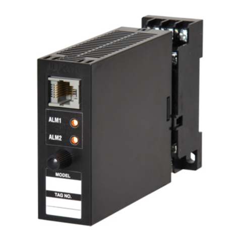
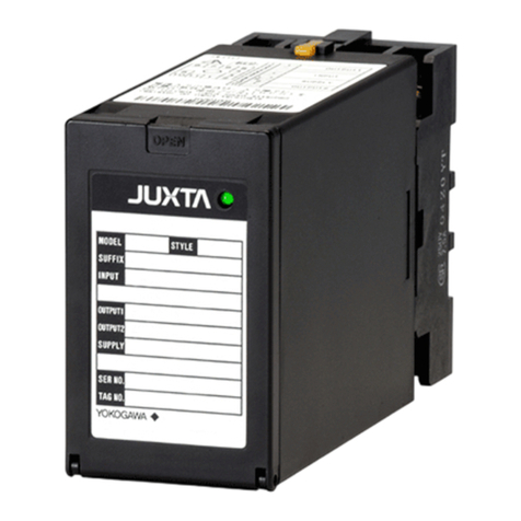
The VJD1 is a compact, plug-in type tachogenerator converter
that receives single-phase, AC voltage signal from an electric
tachometer and converts it into isolated DC voltage or DC current
signals.
MODEL AND SUFFIX CODES
Model Su󰀩x codes Description
VJD1 -0 x x -1 xx0/x Tachogenerator Converter
Fixed code
-0 Always -0
Output 11 output
22 outputs
Power supply 6100-240 V AC/DC*1
715-30 V DC*2
Input signal -1 AC voltage signal
Output-1 signal
A4 to 20 mA DC
B2 to 10 mA DC
C1 to 5 mA DC
D0 to 20 mA DC
E0 to 16 mA DC
F0 to 10 mA DC
G0 to 1 mA DC
10 to 10 mV DC
20 to 100 mV DC
30 to 1 V DC
40 to 10 V DC
50 to 5 V DC
61 to 5 V DC
7−10 to +10 V DC
ZCustom order *3
Output-2 signal
A4 to 20 mA DC
61 to 5 V DC
NNo output-2
ZCustom order *3
Fixed code 0Always 0
Option
/SN No socket (with socket if not
specied)
/C0 Coating *4
/FB Fuse bypass *4
*1 Operating range: 85 to 264 V AC/DC
*2 Operating range: 12 to 36 V DC
*3 DC voltage signal or DC current signal
*4 When option code /C0 or /FB is specied, the conformity to the safety
and EMC standards is excluded. CE marking is not applicable.
Note: An exclusive User’s Manual might be attached to the
products whose su󰀩x codes or option codes contain the code
“Z” (made to customers’ specications). Please read it along
with this manual.
Model VJD1
Tachogenerator Converter
(Isolated Single-output and
Isolated Dual-output Types)
2IM 77J01D01-01E 1st Edition
1. MOUNTING METHOD
CAUTION
●Plug/disconnect the main unit into/from the
socket vertically to the socket face. Otherwise the
terminals may bend and it may cause bad contact.
●The converter shall not tilt 5 degrees or more in
either direction when installed.
●When the converter is not connected to the socket,
it is necessary to protect the socket against ingress
of dust to the connector part.
●Keep this product in a conductive bag when
plugged out, during transport or storage.
1.1 Wall Mounting
Loosen the main unit-xing screw of the product and pull out the
main unit from the socket. Fix the socket on the wall with screws.
Next, insert the main unit into the socket and fasten the main unit
with the main unit-xing screw.
29.5 or more
22±0.2
2-M4 or
2-ø
4.5 or more
Mounting Dimensions
Unit: mm
59±0.3
Main unit-fixing screw
Socket
Main unit
Threaded hole for
fixing the main unit
Mounting screws
1.2 DIN Rail Mounting
Insert a DIN rail into the upper part of the DIN rail groove on the
rear of the socket, and then slide the slide lock at the lower part of
the socket upwards until the socket is xed into position as shown
below.
DIN rail
DIN rail
(Rear of socket)
Slide lock
DIN rail
Fit into here
Push
1.3 Mounting Using a Multi-mounting Base
When using a multi-mounting base, see the User’s Manual for
VJCE-01A (VJ Mounting Base for communication) (IM 77J01C51-
11E).
1.4 Using a Duct
When using a wiring duct, install the duct at leaset 30 mm away
from the top and bottom faces of the main unit.
2. INSTALLATION AND ENVIRONMENTAL
CONDITIONS
• Avoid the following environments for installation locations:
Areas with vibrations, corrosive gases, dust, water, oil,
solvents, direct sunlight, radiation, a strong electric eld,
and/or a strong magnetic eld, direct radiant heat, wind,
temperature uctuation.
• If there is any risk of a surge being induced into the power line
and/or signal lines due to lightning or other factors, a dedicated
lightning arrester should be used as protection for both the
product and a eld-installed device.
• Use indoors at an altitude of 2000 m or less.
• Operating temperature/humidity range: −10 to 55°C (−10
to 45°C for side-by-side mounting*)/5 to 90%RH (no
condensation)
* If the previous model (style S3.xx earlier) is installed
together, the ambient temperature is 0 to 40°C.
• Continuous vibration: (at 5 to 9 Hz) Half amplitude of 3 mm or
less (at 9 to 150 Hz) 9.8m/s2 or less, 1 oct/min for 90 minutes
each in the three axis directions
• Impact: 98 m/s2or less, 11 ms, 3 axes, 6 directions, 3 times
each
3IM 77J01D01-01E 1st Edition
3. EXTERNAL WIRING
WARNING
●To avoid the risk of an electric shock, turn o󰀨 the
power supply and use a tester or similar device to
ensure that no power is supplied to a cable to be
connected, before carrying out wiring work.
●Do not operate the product in the presence of
ammable or explosive gases or vapors. To do so is
highly dangerous.
●Use of the product ignoring the specications may
cause overheating or damage. Before turning on
the power, ensure the following:
•Power supply voltage and input signal value
applied to the product should meet the required
specications.
•The external wiring to the terminals and wiring to
ground are as specications.
Wiring should be connected to the terminals on the socket of the
product. The terminals for external connections are of M3 screws.
Use crimp-on terminal lugs for connections to the terminals.
• Recommended cables: A nominal cross-sectional area of
0.5 mm2or thicker for signal cables, and that of 1.25 mm2or
thicker for power cables.
Wiring Diagram
1011
3 2 1
5
789
Power supply
1110 8
L+N–GND
+
–
Input
5
2
Output-2
+
–
9
7
Output-1
1
3
V
±
TG
CAUTION
●Do not use output-2 for the isolated single-output
type.
●The power line and input/output signal lines should
be installed away from noise-generating sources.
Other wise accuracy cannot be guaranteed.
●Make sure to earth ground the ground terminal
through minimum resistance. The length and
thickness of the grounding cable should be as
short and thick as possible. Directly connect the
lead from the ground terminal (terminal no. 8) of
the product to the ground. Do not carry out daisy-
chained inter-ground terminal wiring.
●The product is sensitive to static electricity;
exercise care in operating it. Before you operate
the product, touch a nearby metal part to discharge
static electricity.
●If the ambient temperature is 50 °C or more, please
use the cable that the rated temperature is 70 °C or
more.
4. MAINTENANCE
The product starts running immediately when the power is turned
on; however, it needs 10 to 15 minutes of warm-up before it
meets the specied performance.
4.1 Calibration Apparatus
• A AC voltage current standard (YOKOGAWA 2558A or the
equivalent)
• A digital multimater (YOKOGAWA DM7560 or the equivalent)
• A precision resistor of 250 Ω ± 0.01%, 1 W
4.2 Calibration Procedure
1. Connect the instruments as shown below. First adjust the
output-1 signal and then the output-2 signal.
1011
3 2 1
5
789
Power supply
1110 8
L+N–GND
1
3
V
±
Input
AC voltge/
current
standard
DMM
2
5
Output-2
R
R: 250 Ω
precision resistor
for current output
+
–
DMM
7
9
Output-1
R
+
–
2. Use the AC voltage/current standard and apply input signals
equivalent to 0, 25, 50, 75, and 100% of the input span to the
product.
3. Check to see the corresponding output voltages are 0, 25, 50,
75, and 100% respectively and within the specied accuracy
rating. “R” is used for current output.
• If the output signals are out of the accuracy rating range,
adjust the output signal level using the zero and span
adjustment volumes on front face of the product.
Zero-adjustment volume
Output-1
Span-adjustment volume
Zero-adjustment volume
Output-2
Span-adjustment volume
4IM 77J01D01-01E 1st Edition
5. SAFETY AND EMC STANDARDS
The following will be acquired.
Safety:
IEC/EN 61010-1 compliance (CE)
IEC/EN 61010-2-030 compliance (CE)
CAN/CSA-C22.2 No.61010-1 (CSA)
CAN/CSA-C22.2 No.61010-2-030 (CSA)
UL61010-1 (CSA NRTL/C)
UL61010-2-030 (CSA NRTL/C)
Overvoltage category: II
Pollution degree: 2
Measurement category: O (other)
Rated power supply voltage: 15-30 V DC (±10%) 2.4 W or
100-240V AC/DC (±10%)
50/60 Hz 2.4 W 6.5 VA
Rated voltage (Input signal) : Order range
Rated voltage (Analog output signal): −10 to +10 V DC,
0 to 20 mA DC
Rated transient overvoltage: 1500 V (*)
* This is a reference safety standard value for the
measurement Category O. This value is not necessarily
a guarantee of instrument performance.
CAUTION
This instrument is for Measurement Category O
(other). Do not use it for measurements in locations
falling under Measurement Categories II, III, and IV.
Internal Wiring
Outlet
Entrance
Cable
III T
O
II
IV
Measurement
category
Description Remarks
O (other) For measurements
performed on circuits not
directly connected to MAINS.
II CAT.II For measurements
performed on circuits directly
connected to the low-voltage
installation.
Appliances,
portable
equipments,
etc.
III CAT.III For measurements
performed in the building
installation.
Distribution
board, circuit
breaker, etc.
IV CAT.IV For measurements
performed at the source of
the low-voltage installation.
Overhead
wire, cable
systems, etc.
CAUTION
Precautions for using this product to comply with
safety standards:
The insulation class between the input and output of
this product is basic insulation (150V). When installing
this product, make sure that the insulation class of this
product satises the requirements for use. In addition,
supplementary insulation is required between the
output of this product and the connected equipment.
EMC standards:
•CE:
EN 61326-1 Class A, Table 2
EN 61326-2-3
* The instrument continues to operate at a measurement
accuracy of within ±20% of the range during testing.
EN 55011 Class A, Group 1
EN 61000-3-2
EN 61000-3-3
•RCM:
EN 55011 Class A, Group 1
•KC:
Electromagnetic wave interference prevention standard,
electromagnetic wave protection standard
CAUTION
Caution to comply with EMC standards: When
operating this instrument by external power supply,
use an independent power unit conforming to CE-
marking. Be sure to use the lightning arrester to
comply EMC standards.
Note: When option code /C0 or /FB is specied, the conformity to
the safety and EMC standards is excluded.
6. ENVIRONMENT STANDARD
EU RoHS directive: EN IEC 63000
(However, when option code /C0 or /FB is specied, CE mark-
ing is not applicable because the product does not comply
with the Safety and EMC standards.)
7. TRANSPORT AND STORAGE CONDITIONS
• Temperature: −25 to 70°C
• Temperature change rate: 20°C per hour or less
• Humidity: 5 to 95%RH (no condensation)
CAUTION
Keep this product in a conductive bag when plugged
out, during transport or storage.

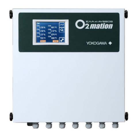
Other YOKOGAWA Media Converter manuals

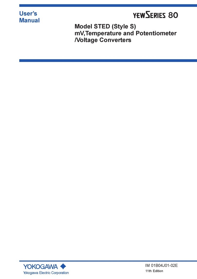
YOKOGAWA YewSeries 80 STED Style S User manual

YOKOGAWA

YOKOGAWA YewSeries 80 STED Style S User manual

YOKOGAWA PH450G User manual

YOKOGAWA

YOKOGAWA PH450G User manual

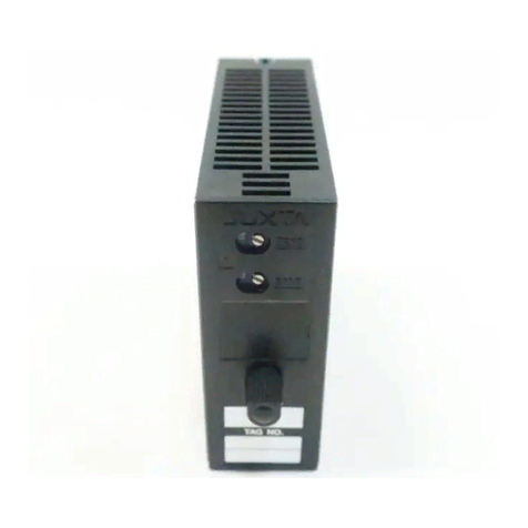
YOKOGAWA JUXTA VJT6 Series User manual

YOKOGAWA

YOKOGAWA JUXTA VJT6 Series User manual

YOKOGAWA JUXTA VJP8 User manual

YOKOGAWA

YOKOGAWA JUXTA VJP8 User manual

YOKOGAWA JUXTA MG1 PT User manual

YOKOGAWA

YOKOGAWA JUXTA MG1 PT User manual

YOKOGAWA YFGW610 User manual

YOKOGAWA

YOKOGAWA YFGW610 User manual

YOKOGAWA FLXA402 User manual

YOKOGAWA

YOKOGAWA FLXA402 User manual

YOKOGAWA SC402G User manual

YOKOGAWA

YOKOGAWA SC402G User manual

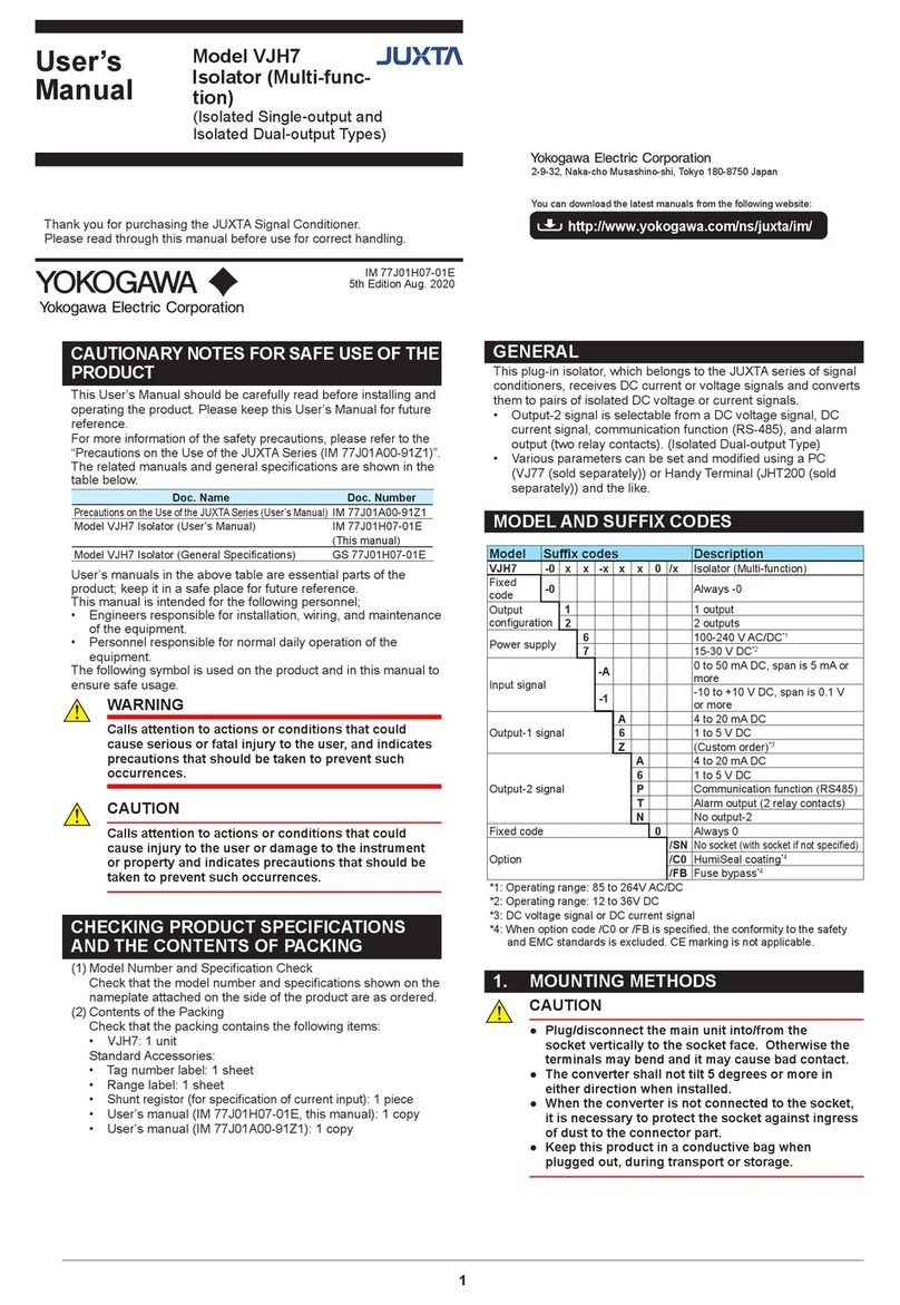
YOKOGAWA JUXTA VJH7 User manual

YOKOGAWA

YOKOGAWA JUXTA VJH7 User manual

YOKOGAWA Yew 80 Series User manual

YOKOGAWA

YOKOGAWA Yew 80 Series User manual

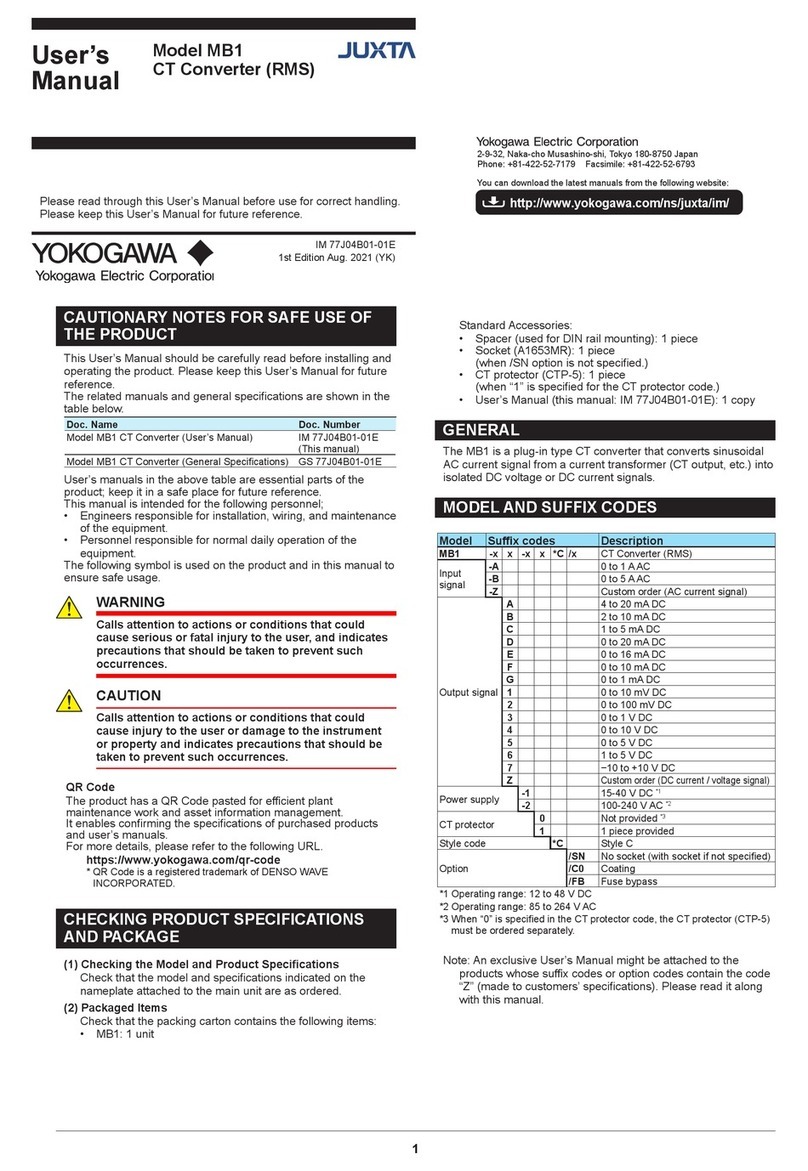
YOKOGAWA JUXTA MB1 User manual

YOKOGAWA

YOKOGAWA JUXTA MB1 User manual

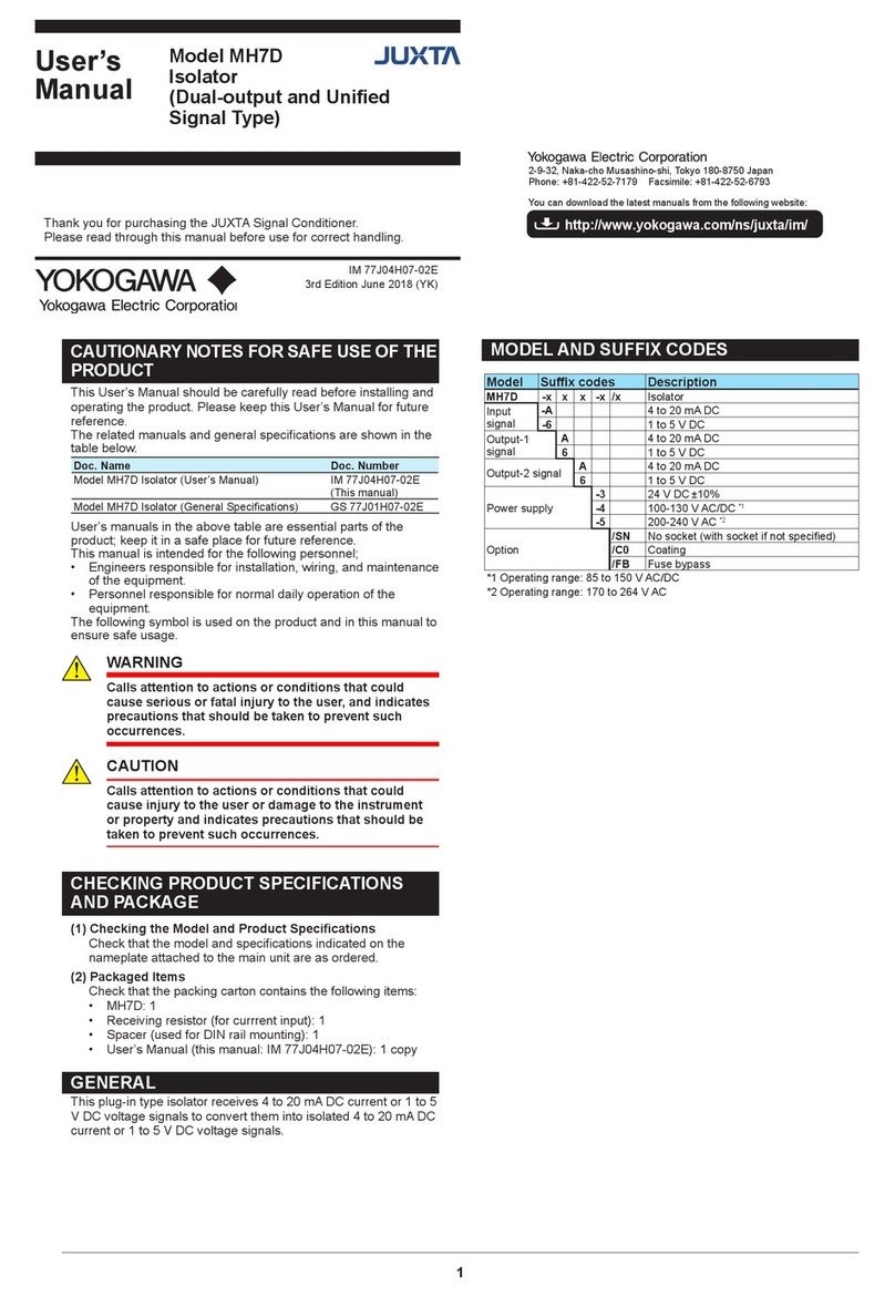
YOKOGAWA JUXTA MH7D User manual

YOKOGAWA

YOKOGAWA JUXTA MH7D User manual

YOKOGAWA YFGW610 User manual

YOKOGAWA

YOKOGAWA YFGW610 User manual

YOKOGAWA SC150 User manual

YOKOGAWA

YOKOGAWA SC150 User manual

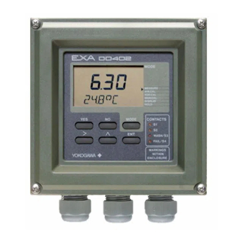
YOKOGAWA EXA DO402G User manual

YOKOGAWA

YOKOGAWA EXA DO402G User manual

YOKOGAWA FLXA402 User manual

YOKOGAWA

YOKOGAWA FLXA402 User manual

YOKOGAWA Vitesse FA-M3V User manual

YOKOGAWA

YOKOGAWA Vitesse FA-M3V User manual

YOKOGAWA Juxta VJG1 User manual

YOKOGAWA

YOKOGAWA Juxta VJG1 User manual

YOKOGAWA VigilantPlant PK200 User manual

YOKOGAWA

YOKOGAWA VigilantPlant PK200 User manual

YOKOGAWA JUXTA VJB1 User manual

YOKOGAWA

YOKOGAWA JUXTA VJB1 User manual

YOKOGAWA PH450G User manual

YOKOGAWA

YOKOGAWA PH450G User manual

YOKOGAWA 3142 User manual

YOKOGAWA

YOKOGAWA 3142 User manual

YOKOGAWA FLXA402 Manual

YOKOGAWA

YOKOGAWA FLXA402 Manual

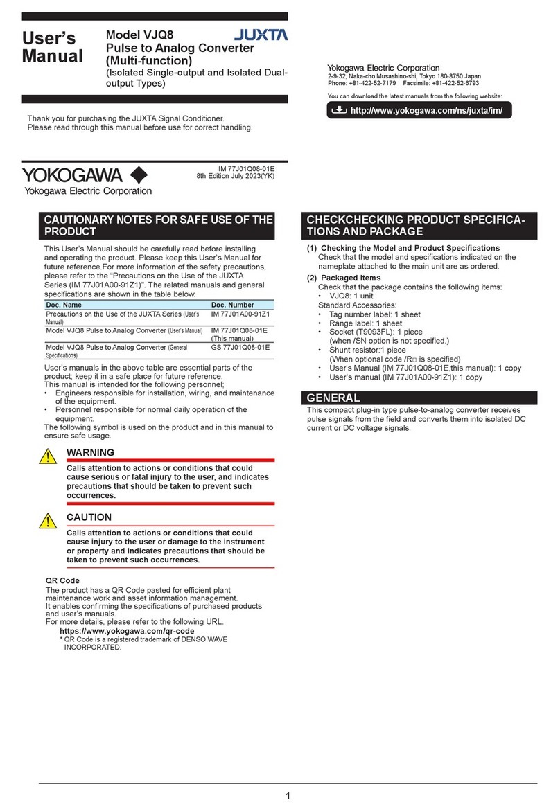
YOKOGAWA JUXTA VJQ8 Series User manual

YOKOGAWA

YOKOGAWA JUXTA VJQ8 Series User manual

Popular Media Converter manuals by other brands

Lynx C AD 3321 D Reference manual

Lynx

Lynx C AD 3321 D Reference manual

CEL-MAR ADA-4021 user manual

CEL-MAR

CEL-MAR ADA-4021 user manual

Asus Xonar Essence STU Quick start guides

Asus

Asus Xonar Essence STU Quick start guides

Imagine SEL-2FS1 Installation and operation manual

Imagine

Imagine SEL-2FS1 Installation and operation manual

Stereoping synth programmer Operation manual

Stereoping

Stereoping synth programmer Operation manual

TR-Electronic Profibus 582 Series user manual

TR-Electronic

TR-Electronic Profibus 582 Series user manual

Fujitsu IP-900E Hardware user's guide

Fujitsu

Fujitsu IP-900E Hardware user's guide

ADF Web HD67871-A1-2A user manual

ADF Web

ADF Web HD67871-A1-2A user manual

MACH SYSTEMS 100BASE-T1 user manual

MACH SYSTEMS

MACH SYSTEMS 100BASE-T1 user manual

Linear Technology DC257 Demo Manual

Linear Technology

Linear Technology DC257 Demo Manual

OTS FT010AB Series Installation and operation manual

OTS

OTS FT010AB Series Installation and operation manual

StarTech.com MCMGBSC15 Spec sheet

StarTech.com

StarTech.com MCMGBSC15 Spec sheet

OT Systems FT210CB Series Installation and operation manual

OT Systems

OT Systems FT210CB Series Installation and operation manual

Versitron M7260PA user manual

Versitron

Versitron M7260PA user manual

Transition Networks E-TBT-FRL-05(L) user guide

Transition Networks

Transition Networks E-TBT-FRL-05(L) user guide

Huidu Technology HDP501 user manual

Huidu Technology

Huidu Technology HDP501 user manual

Speaka Professional SP-5587128 operating instructions

Speaka Professional

Speaka Professional SP-5587128 operating instructions

Transition Networks CGFEB1xxx-15x user guide

Transition Networks

Transition Networks CGFEB1xxx-15x user guide

manuals.online logo
manuals.online logoBrands
  • About & Mission
  • Contact us
  • Privacy Policy
  • Terms and Conditions

Copyright 2025 Manuals.Online. All Rights Reserved.