YOKOGAWA YEWSERIES 80 SDBS (Style S) User manual

User’s
Manual
Yokogawa Electric Corporation
IM 01B04T02-02E
14th Edition
Model SDBS (Style S)
Distributor


Toc-1
IM 01B04T02-02E
1
2
3
App
1
2
3
5
6
7
8
4
Contents
Chapter 1 Introduction
1.1 Inspection............................................................................................................................1-2
1.2 Documentation Conventions ...............................................................................................1-3
1.3 Notice ..................................................................................................................................1-4
Chapter 2 General
2.1 Standard Specifications ......................................................................................................2-2
2.2 Model and Suffix Codes ......................................................................................................2-3
Chapter 3 Installation
3.1 External Wiring....................................................................................................................3-2
Chapter 4 Principle of Operation
Chapter 5 Operation
5.1 Names of Components .......................................................................................................5-2
5.2 Pre-operational Checks.......................................................................................................5-3
Chapter 6 Maintenance
6.1 Test Equipment ...................................................................................................................6-2
6.2 Calibration ...........................................................................................................................6-3
6.3 List of Replaceble Parts ......................................................................................................6-4
Chapter 7 Troubleshooting
Chapter 8 Power Supply Terminal Connections (Options /TB, /A2TB, and /REK)
8.1 External View and Names of Components .........................................................................8-2
8.2 Power Supply and Ground Wiring.......................................................................................8-3
General Specifications

Blank

1-1
IM 01B04T02-02E
1
2
3
App
1
2
3
5
6
7
8
4
Introduction
Introduction
This manual describes the functions and operations of the SDBS Distributor.
● IntendedReaders
This manual is intended for personnel in charge:
• Installation and wiring
• Instrumentation and setup of the function
• Operation and monitoring of the controller
• Maintenance of equipment
● RelatedDocuments
The following documents all relate to the SDBS Distributorter. Read them as necessary.
Manual Title Manual No. Description
Rack-Mounted Instruments IM 1B4F2-01E Describes mounting and wiring for the YS80 rack-mounted instruments.
YEWSERIES 80 Installation Manual TI 1B4A9-01E Describes the installation conditions of YS80 instruments.
Chapter 1 Introduction
1-2 IM 01B04T02-02E
1.1 Inspection
The SDBS distributor is shipped only after stringent inspection at the factory. Visually inspect
the product upon delivery to make sure it is not damaged in any way.
Store the box and inner packing material of the package in a safe place - they may be
needed if there is a problem with the product and it needs to be sent back for repair.
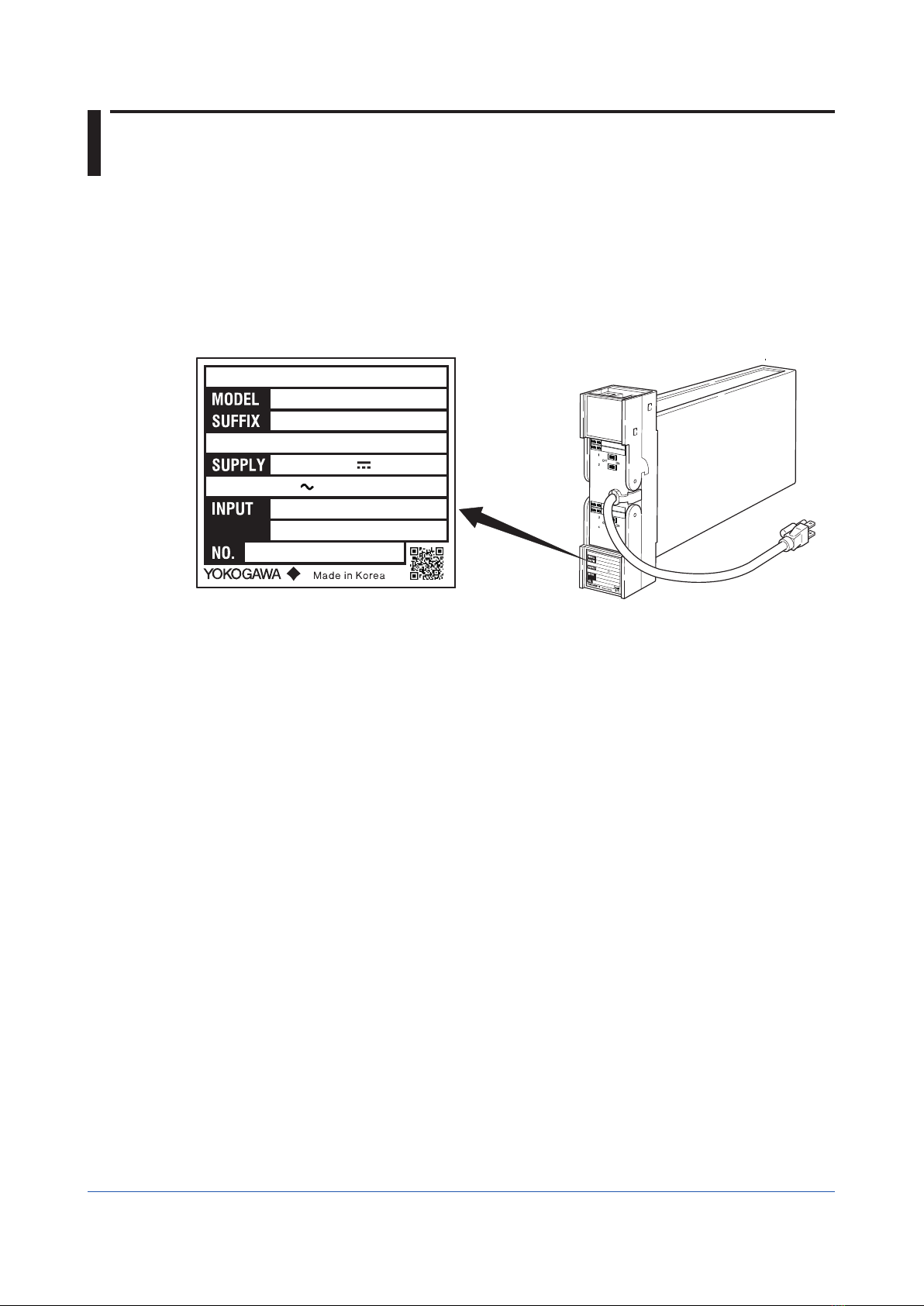
Check of Model and Suffix Codes
The model and suffix codes are indicated on the Name plate attached to the front cover of
the instrument. Crosscheck this information with the model and suffix codes of Section 2.2
to ensure that the product is as specified in the order.
F0101.ai
100-120VAC 50/60Hz
DISTRIBUTOR
SDBS
-140*S
XXXXXXXXX
4-20mADC
260mA
15.0VA
24-110VDC
100-120VAC 50/60Hz
DISTRIBUTOR
SDBS
-140*S
XXXXXXXXX
4-20mADC
260mA
15.0VA
24-110VDC
Figure 1-1 Name plate for Thermocouple Input (Description example)
Confirmation of the Package Contents
Check the package contents against the list below. If anything is missing or damaged,
immediately contact the sales office from which you purchased the product or your nearest
Yokogawa representative.
• SDBS Distributor ...............................................................................................1
• Precautions on the Use of the YS80 Series ......................................................1
Downloadable Electronic Manuals
You can download the latest manuals from the following website:
http://www.yokogawa.com/ns/ys/
1-3
IM 01B04T02-02E
1
2
3
App
1
2
3
5
6
7
8
4
Introduction
1.2 Documentation Conventions
This manual uses the following notational conventions.
Symbols
The following symbols are used in this manual.
Markings
Indicates that operating the hardware or software in a particular
manner may damage it or result in a system failure.
Draws attention to information that is essential for understanding the
operation and/or features of the product.
Note Gives additional information to complement the present topic and/or
describe terms specific to this document.
Gives reference locations for further information on the topic.
Description of Displays
Some of the representations of product displays shown in this manual may be exaggerated,
simplified, or partially omitted for reasons of convenience when explaining them.
QR Code
The product has a QR Code pasted for efficient plant maintenance work and asset
information management. It enables confirming the specifications of purchased products and
user’s manuals.
For more details, please refer to the following URL.
https://www.yokogawa.com/qr-code
QR Code is a registered trademark of DENSO WAVE INCORPORATED.
1-4 IM 01B04T02-02E
1.3 Notice
This Instruction Manual
• This manual should be passed on to the end user. Keep at least one extra copy of the
manual in a safe place.
• Read this manual carefully to gain a thorough understanding of how to operate this
product before you start using it.
• This manual is intended to describe the functions of this product. Yokogawa Electric
Corporation (hereinafter simply referred to as Yokogawa) does not guarantee that these
functions are suited to the particular purpose of the user.
• Under absolutely no circumstances may the contents of this manual, in part or in whole,
be transcribed or copied without permission.
• The contents of this manual are subject to change without prior notice.
• Every effort has been made to ensure accuracy in the preparation of this manual. Should
any errors or omissions come to your attention however, please contact your nearest
Yokogawa representative or sales office.
Protection, Safety, and Prohibition against Unauthorized Modification
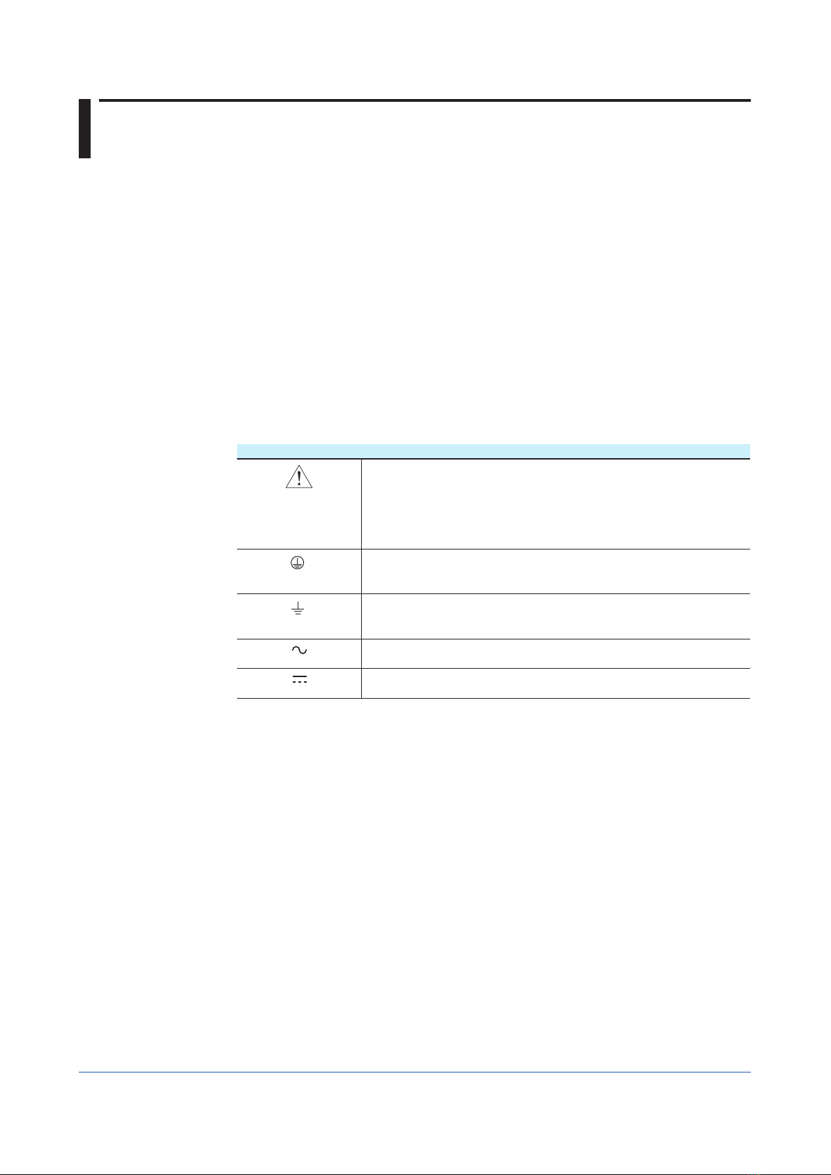
• The following safety symbols are used on the product and in this manual.
Markings
If this symbol is indicated on the product, the operator should refer
to the explanation given in the instruction manual in order to avoid
personal injury or death to either themselves or other personnel, and/
or damage to the instrument. The manual describes that the operator
should exercise special care to avoid shock or other dangers that may
result in injury or loss of life.
Protective ground terminal:
This symbol indicates that the terminal must be connected to ground
prior to operating the equipment.
Function ground terminal:
This symbol indicates that the terminal must be connected to ground
prior to operating the equipment.
AC voltage:
This symbol indicates that AC voltage is present.
DC voltage:
This symbol indicates that DC voltage is present.
• In order to protect the product and the system controlled by it against damage and ensure
its safe use, make certain that all of the instructions and precautions relating to safety
contained in this document are strictly adhered to. Yokogawa does not guarantee safety
if products are not handled according to these instructions.
• If protection/safety circuits are to be used for the product or the system controlled by it,
they should be externally installed on the product.
• When you replace the parts or consumables of the product, only use those specified by
Yokogawa.
• If the product is to be used in systems with special requirements for human safety, such
in as nuclear power and radiation related equipment, railway facilities, aircraft facilities,
and medical devices, please consult with your sales representative.
• Do not modify the product.
Force Majeure
• Yokogawa does not make any warranties regarding the product except those mentioned
in the WARRANTY that is provided separately.
• Yokogawa assumes no liability to any party for any loss or damage, direct or indirect,
caused by the use or any unpredictable defect of the product.

2-1
IM 01B04T02-02E
1
2
3
App
1
2
3
5
6
7
8
4
General
General
SDBS distributor is both designed to supply operating power to two-wire type transmitters
and convert 4 to 20 mA DC current signal from these transmitters into output signals.
SDBS distributor is designed for four inputs and is available in a loop isolation type.
SDBS distributor have built-in current limiters allowing normal operation even when a short-
circuit occurs on the transmitter side.
F0201.ai
Figure 2-1 External View
Chapter 2 General

2-2 IM 01B04T02-02E
2.1 Standard Specifications
Please see the General Specifications (GS 01B04T02-02E) at the end of this manual.

2-3
IM 01B04T02-02E
1
2
3
App
1
2
3
5
6
7
8
4
General
2.2 Model and Suffix Codes
Model Suffix Codes Option Codes Description
SDBS Distributor
Isolation, Inputs -14 Loop isolation, four inputs
Suffix Codes 0 Always 0
Style Code *S Style S
Option Codes (*1) (*2) /NHR
/FBP
/LOCK
/WSW
/REK
/TB
/A2TB
/A2ER
Without rack case
Power supply fuse bypass
Power supply plug with lock
With spring washer
Mount to same line with EK series rack
With power supply terminal
220V version with power supply terminal
220V version with power supply plug
*1: /LOCK, /REK, /TB, /A2TB, and /A2ER cannot be specified together.
*2: /FBP, /A2TB, and /A2ER cannot be specified together.

Blank

3-1
IM 01B04T02-02E
Installation
1
2
3
App
1
2
3
5
6
7
8
4
Installation
For details of the installation procedure and wiring precautions, refer to instruction manual
“Installation of Rack-Mounted Instruments” (IM 1B4F2-01E).
Chapter 3 Installation
3-2 IM 01B04T02-02E
3.1 External Wiring
(a) To prepare cables for connection to each terminal, install crimp-on solderless lugs for
4 mm screw on the end of each cable.
(b) Draw the internal unit out from the rack case.
(c) Connect the cables to the correct terminals by referring to Table 3-1.
(d) Replace the internal unit into the rack case after completing the wiring.
(e) Always replace the terminal cover after completing the wiring.
The terminal cover cannot be replaced if the internal unit is not installed in the rack
case. The terminal cover should be securely replaced because it has the function of
locking the internal unit.
K
J
H
F
D
C
B
A
8
7
6
5
4
3
2
1
OUT
IN
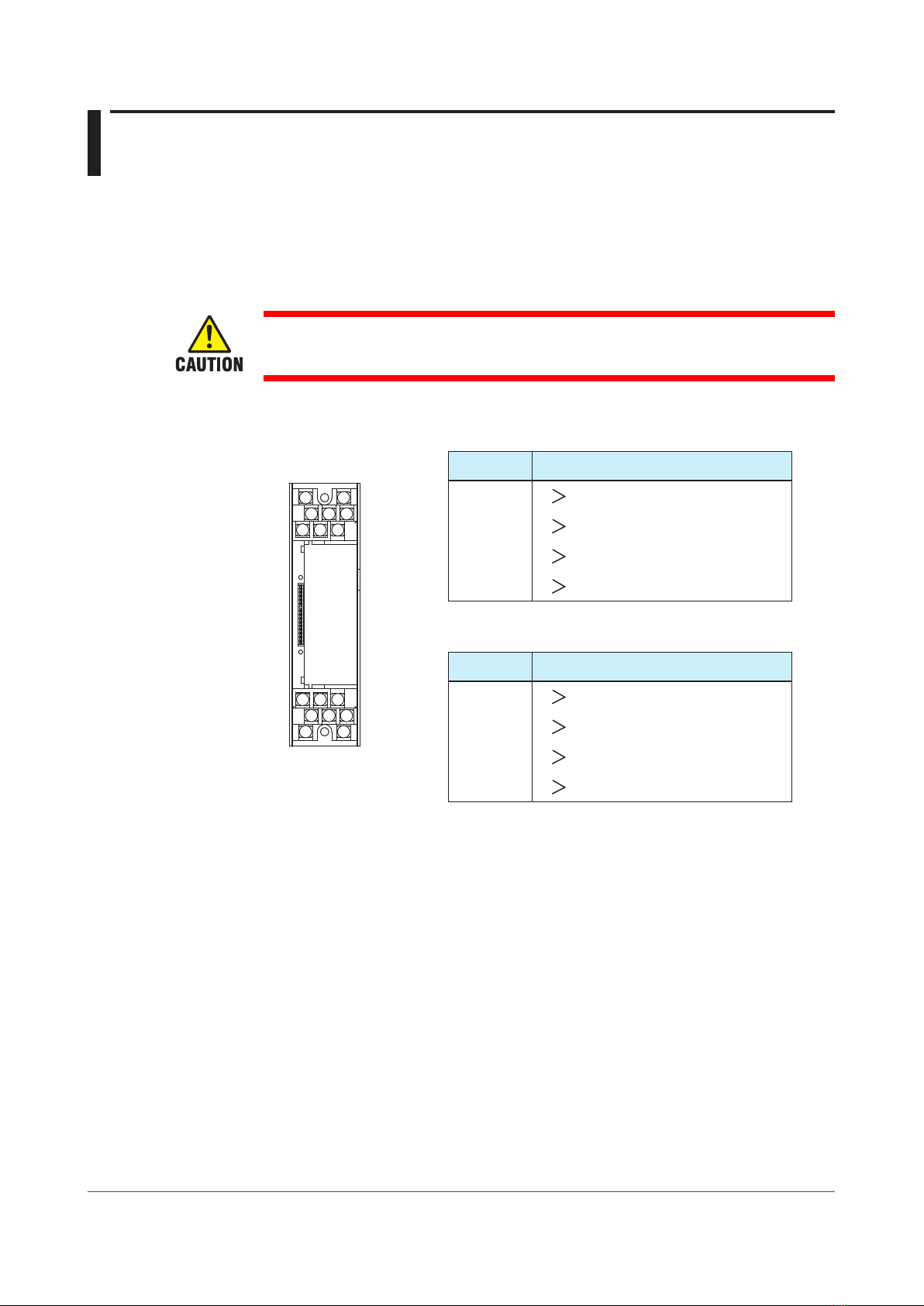
Terminal arrangement
Figure 3-1 Terminal Layout
Table 3-1 Terminal Connections
Terminal
Designation Description
A + Output 1 (Transmitter 1)
B -
C + Output 3 (Transmitter 3)
D -
F + Output 2 (Transmitter 2)
H -
J + Output 4 (Transmitter 4)
K -
Do not connect to the output terminal when the terminal is not in
use.
Terminal
Designation Description
1 + Transmitter 1 (Input 1)
2 -
3 + Transmitter 3 (Input 3)
4 -
5 + Transmitter 2 (Input 2)
6 -
7 + Transmitter 4 (Input 4)
8 -
Applicable Cables
(1) Signal circuit wiring
• Cross-sectional area of the cable conductor: 0.5 to 0.75 mm2
• Examples of applicable cables: Signal core PVC insulated flexible cable (VSF)
stranded wires (JIS C 3306); heat-resistant vinyl-
insulated cable (UL style 1007)
(2) Power supply wiring
• Cross-sectional area of the cable conductor: 1.25 to 2.00 mm2
• Examples of applicable cables: 600 V PVC insulated cable (1 V) stranded wires (JIS
C 3307); PVC insulated cable for electrical apparatus
(KIV) stranded wires (JIS C 3316)

4-1
IM 01B04T02-02E
Principle of Operation
1
2
3
App
1
2
3
5
6
7
8
4
Principle of Operation
The SDBS supplies power to a two-wire type transmitter through the current limiter CL and
converts a 4 to 20 mA output current signal from the transmitter into a 1 to 5 V DC signal.
CL prevents excessibe current if a short-curcuit occurs in the field wiring.
Each of the four isolated loop distributor circuits in SDBS is provided with an ON/OFF switch
for the transmitter.
V1
CL
IN 1
OUT 1
250 Ω
+
–
Two-wire type transmitter
V2
CL
IN 2
OUT 2
250 Ω
+
–
V3
CL
IN 3
OUT 3
250 Ω
+
–
V4
CL
IN 4
OUT 4
250 Ω
+
–
CL
SWR
: Current limiter
: Power regulator unit
F0401.ai
V1V2V3
SWR
GNDNL
V4
V3
SWR
Figure 4-1. Functional Block Diagram
Chapter 4 Principle of Operation

Blank

5-1
IM 01B04T02-02E
Operation
1
2
3
App
1
2
3
5
6
7
8
4
Operation
Once the installation and wiring are completed, this distributor can be placed in operation by
simply turning on the power switch. This distributor does not require any adjustments, but
the inspection and checks described in Section 5-2 should be made before the unit is placed
in operation.
Chapter 5 Operation
5-2 IM 01B04T02-02E
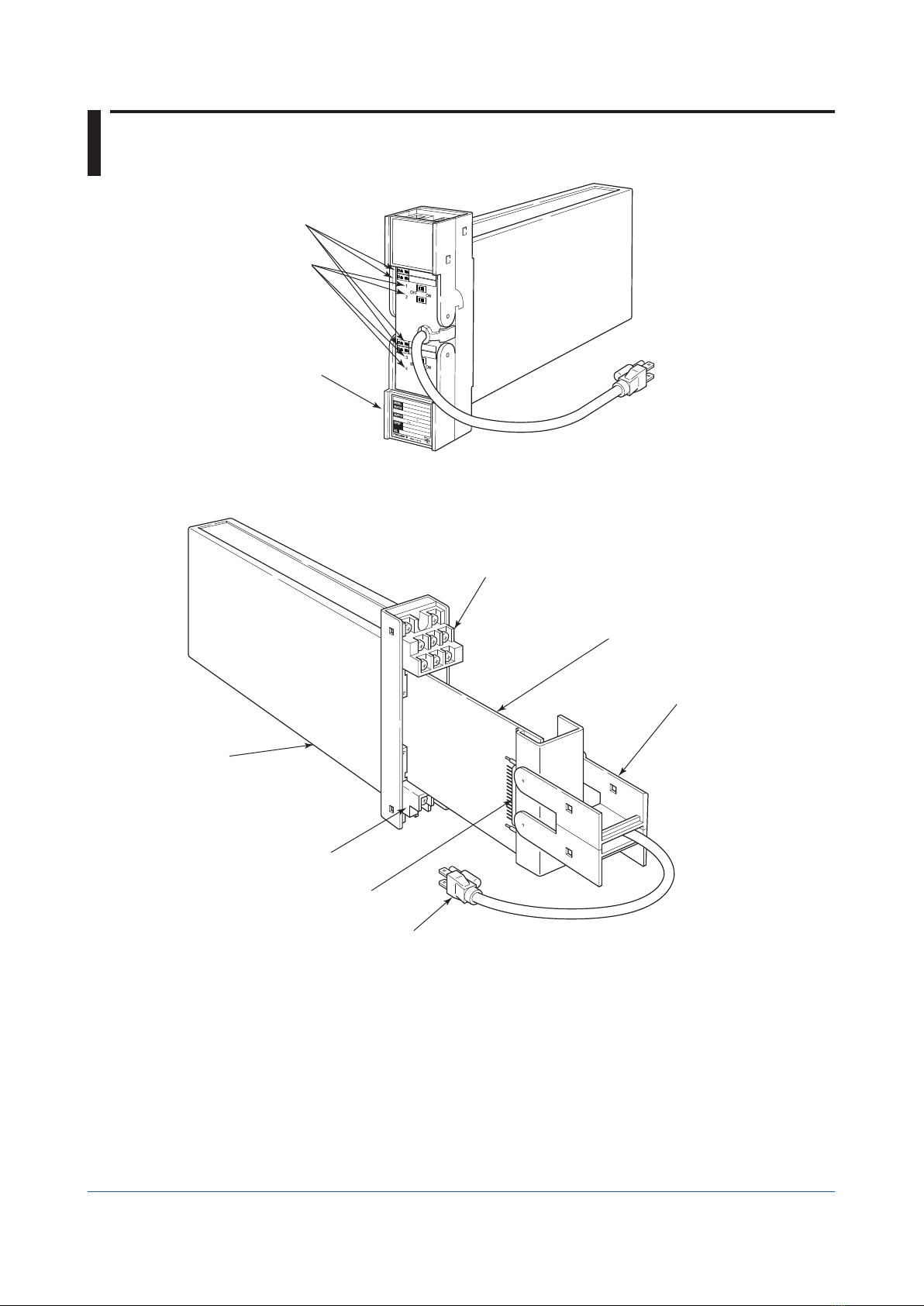
5.1 Names of Components
F0501.ai
Output terminal block
Main printed circuit board
Terminal cover handle
for drawing out
the internal instrument
Two-pole plug with earthing contact
Multi-pin connector
Input terminal block
Rack case
Tag plate
ON / OFF power
switch for
transmitter
Nameplate
100-120VAC 50/60Hz
DISTRIBUTOR
SDBS
-140*S
XXXXXXXXX
4-20mADC
260mA
15.0VA
24-110VDC
Figure 5-1. Names of Various Components

5-3
IM 01B04T02-02E
Operation
1
2
3
App
1
2
3
5
6
7
8
4
5.2 Pre-operational Checks
Inspect and check the following points before entering the unit into normal operation.
(1) Draw the internal unit out from the rack case and insure that the specified fuse is
installed in the fuse holder at the back of the internal unit.
(2) Before sliding the internal unit back into the rack case, check that the rack case
connector is securely connected to the internal unit.
(3) Check that the wires are securely connected to the correct terminals on the terminal
block.
(4) Check that the power plug is securely connected in a power outlet with a grounding
contact.
(5) For SDBS, set the switch at the front of the distributor to the ON position. If any
distributor circuit is not used, set the corresponding switch to the OFF position.
To turn switches ON or OFF, use an appropriate tool. Take care not to damage the
switch.

Blank
Table of contents
Popular Power Distribution Unit manuals by other brands

Walther Systemtechnik
Walther Systemtechnik TBV-H-01 operating manual

ATEN
ATEN PE5216 quick start guide

Xtreme Power Conversion
Xtreme Power Conversion SPD-0215 User & installation manual

Victron energy
Victron energy BatteryProtect 48V 100A manual

LifeSafety Power
LifeSafety Power FlexPower N24 installation manual

ABB
ABB COM600 series user manual


