N24 Installation Manual
4 5
9
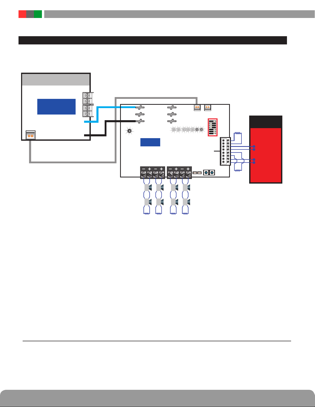
Zone Inputs (TB3)
The inputs for activating the outputs of the N24 board. The
usage of these inputs varies based on the settings of the DIP
switches – see DIP Switch settings for more information
(item 10).
• INxA EOL (Class B) or Return + (Class A)
• INxB EOL (Class B) or Return – (Class A)
• INxC Input -
• INxD Input +
(See input example wiring diagrams for details on Page 4.)
These terminals are not supervised by the N24 board -
supervision of these terminals and the entire input loop is
performed by the FACP.
These terminals are removable and accept wire sizes from
AWG14-AWG22.
bk
Configuration DIP Switches (SW3)
These switches configure the operation of the N24 board.
Note that Switches 1 and 2 MUST be ON when using any of
the Output Synchronization Protocols.
Refer to the chart below for settings:
b
FlexIO Connection
This connector supplies the fault and FAI status between the
FPO power supply system and the N24 board. The appropriate
cable is supplied with the N24 board. See the FPO power supply
manual for more information.
b
Input Power LED
This LED indicates that power is available at the input of the
N24 board. If this LED is not lit, check the Input Fuse of the
N24 and voltage at the B1/B2 power input.
b
Status LEDs
These LEDs indicate the status of the N24 board as follows:
IN1 / IN2 Light RED when a valid signal is received at
the corresponding input terminals. These
LEDs may flash if a coded input is applied
to the respective input.
OUT1 - OUT4 Light YELLOW if a fault is detected on the
corresponding output terminals. Faults
detected include open, short, or overcurrent.
COMFLT Lights YELLOW if any fault condition
is detected by the N24 board. Faults
detected include open or shorted outputs,
output overcurrent, and invalid Dip switch
configurations.
N24 – Accessory Overview
Switch Number
1234567
Input Configuration
IN1 controls all outputs Off Off
IN2 not used
IN1 controls all outputs Off On
IN2 controls all outputs
IN1 controls OUT1 and OUT2 On Off
IN2 controls OUT3 and OUT4
Use this setting when using an
Output Synchronization Protocol setting On On
IN1 controls strobes
IN2 controls horns (only when IN1 is also active)
Output Wiring Configuration
Four Class B Outputs (OUT1, 2, 3, 4) Off Off
Two Class A Outputs (OUT1-2 & OUT3-4) Off On
Two Class B (OUT1, 2)
and One Class A Output (OUT3-4) On Off
One Class A Output (OUT1-2) and Two Class
B Outputs (OUT3,4) On On
Output Protocol Configuration
Steady (follower mode) on OUT1 and 2 Off Off Off
ANSI Temporal Code on OUT3 and 4
ANSI Temporal Code on OUT1, 2, 3, 4 Off Off On
Gentex Synchronization Protocol Off On On
Wheelock Synchronization Protocol On Off On
AMSECO/Potter Synchronization Protocol On On Off