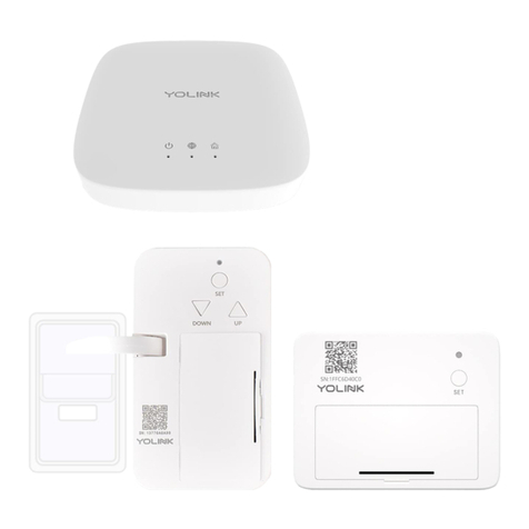
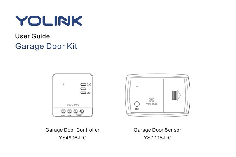
Yolink Garage Door Kit 3 Operation manual

Garage Door Kit 3
YS4906-UC_YS7706-UC
Installaon & User Guide
Rev 1.0
Garage Door Controller
SE T
Garage Door Sensor 2

Contents
In the Box ······· ····· · ·· · ·1······················ ····· ···················································· · ·
Important Noce ·······················································································2
Introducon ······························································································3
Set Up ·······································································································5
Installaon ································································································8
Using the YoLink App ················································································19
About YoLink Control ················································································29
Maintenance ···························································································35
Specificaons ··························································································40
Garage Door Controller Troubleshoong ···················································41
Garage Door Sensor 2 Troubleshoong ······················································42
Warning ··································································································43
···································································45Customer Service & Warranty

In the Box
A. Garage Door Controller
B. Garage Door Sensor 2
C. Power Adapter
D. USB Cable
Signal WireE.
F. Quick Start Guide
1
F.
E.
D.
C.
A. B.
SET

Improper use of your garage door operator/opener can cause property damage and/or serious
injury or death. Install and use your Garage Door Kit 3 only as instructed in this manual
Allow the garage door operator/opener to complete opening or closing before opening/closing
with the controller or app
Do NOT allow children to use the door operator/opener or control it via the app without adult
supervision
Important Noce
If you are uncomfortable working with wiring or electricity, please consult or hire a qualified
electrician
Due to the different control circuit design of garage door opener, Garage Door Controller cannot
compable for all the garage door openers, visit yolink.net to check compability for your
garage door opener from the garage door opener list
2
Garage Door Sensor 2 is not compable for roller doors and slide or slide hinged doors, but only
compable for seconal doors or canopy garage doors

YoLink Smart Garage Door Kit 3 includes two products - YS4906-UC Garage Door Controller,
and YS7706-UC Garage Door Sensor 2
Introducon
O/C Buon
Press once to open / close
the garage door
SET Buon
Status LED
DC 5V+ (Input)
DC 5V- (Input)
Control Terminal
(Output)
3
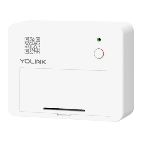
Garage Door Sensor 2: Supervises the posion of your garage door, detecng when it is opened
or closed, and can send alerts or trigger an automaon based on the door opening, closing or
being le open too long
Garage Door Controller: Used for garage door operator or buon control, allows you to control
your garage door from the YoLink app, as well as via popular voice assistants like Alexa and Google
Assistants
SE T
Status LED
SET Buon
Baery Compartment
Includes two AAA
non-rechargeable baeries

The LED light indicates the current status of the controller and sensor:
Green Once
Opening / Closing the door
Slow Blinking Green
Updang
Fast Blinking Red
Removing Connecon to YoLink System
Blinking Red And Green Alternately
Restoring to Factory Defaults
Fast Blinking Green
Establishing Connecon with YoLink System
Blinking Green
Connecng to Cloud
4
Red Once
Alert Mode (Door is Opened or Closed)
Slow Blinking Green
Updang
Fast Blinking Red
Removing Connecon to YoLink System
Blinking Red And Green Alternately
Restoring to Factory Defaults
Fast Blinking Green
Establishing Connecon with YoLink System
Blinking Green
Connecng to Cloud
SET

Set Up
Set Up - First-Time YoLink Users (Exisng users proceed to Add Device, next page)
* Get ready: yourTo set up and use Garage D oor Kit, you will need an Apple iPhone or tablet that is iOS 9.0 or higher, or an Android phone or
tablet t hat is Android 4.4 or higher
Follow the steps below to set up your Garage Door Kit via the YoLink app
Download YoLink app through Apple App Store or Google Play Store
Log in or create a new account if required
Download, and log
in to YoLink app
1
* Make sure your hub is connected to the
internet (green LED indicator is
blinking, blue LED indicator is
always on)
Power
Adapter
Hub
SET
Set up YoLink Hub
2
YoLink Hub is req uired to set up your . Please set up your YoLink Hub first Garage Door Kit
(refer to YoLink Hub manu al)
* Ethernet patch cable (included) to your network
(router, switch, etc.), recommended, but oponal.
Otherwise connect your Hub to your home Wi-Fi
network. Refer to the Hub set up manual for more
informaon:
YS1603-UC_User Guide 5

Add Device
Tap “ ” buon, then scan QR Code on the Garage Door Controller and Garage Door
Sensor 2 in turn
* Garage Door Controller. Aer pairing you will get real-me baery For the best user experience, we suggest you pair your Garage Door Sensor 2 with a
status of your Garage Door Sensor 2, signal level between Garage Door Controller or Garage Door Sensor 2 and the YoLink Hub, and real-me opened or
closed status of your garage door
* If you skip the pairing when adding the device, you can pair them later in the s page of Garage Door ControllerDetail
Tap “ ” buon
to add devices
1
1
2
6
SET

Turn on power of controller aer installaon (refer to Installaon secon on next page),
the Status LED will blink several mes (red, then green). The green LED indicates the device
is online and ready to use
Press the SET buon (on front of sensor) once, the Status LED will blink several mes (red,
then green). The green LED indicates the device is online and ready to use
Turn on power
aer installaon
2
* If the controller is powering on, press
the SET buon once, the Status LED will
blink green, your device is ready to use
* Status LED will blink
red once, then green several
mes(If device is working well
with connecon to the cloud, it will
blink red once only)
7
Press the SET buon (on
front of sensor) once
3
SET
Buon
SET
* Status LED will blink
red once, then green several
mes(If device is working well
with connecon to the cloud, it will
blink red once only)
SET SET

The are very difficult to relocate aer being affixed to the mounng controller and sensor
surface. Test your locaon before affixing the two devices to the surface. controller and sensor
Use masking or painters tape to secure the to the surface. Once you have controller and sensor
the temporarily mounted, test it out. With the app in hand, open or close controller and sensor
the door using app and observing the status of the sensor as shown on the app (Opened or
Closed). Oponally, you may set up your automaon (e.g. turn on a light when the door is
opened) to funconally test the status change of the door - proceed to the following steps for
informaon on creang automaons, then return to this step
Test the Controller and Sensor Locaon Before Installaon
Garage Door Sensor 2 should be mounted on the top panel of garage door and keep the SET
buon at the top and the longer side parallel to the floor, otherwise the status of sensor shown
on the app (Opened or Closed) may be inaccurate
Installaon
Garage Door Controller and Sensor 2 are designed and intended for indoor use only!
8
Avoid allowing the controller and sensor to be exposed to strong impacts or vibraon
Please add the Garage Door Controller and Sensor 2 to the YoLink app before installaon

Remove the
protecve layer
1
Place the controller at the
desired locaon and press
firmly for at least 5 seconds
2
Get Ready to Install the Garage Door Controller
Sloed screwdriver - Number 3 mm may be required
Garage Door Controller
Before starng, choose the appropriate method for your installaon, connecng to your garage
door operator (typically on the ceiling of your garage) or the buon (typically on the wall). For
connecons to the operator (Method A) you may install the Garage Door Controller on the
garage door operator itself, near it on the ceiling, or on the wall, but please note the wiring
requirements: the Garage Door Controller requires the included power adapter, which requires
a 120V receptacle, which may or may not be available at your desired locaon. Also, power
wiring will be required between the Controller and the power adapter and signal wiring will be
required between the Controller and the operator
9

Begin Installaon:
Loosen the screw terminal using a 3 mm sloed screwdriver, connect the first wire to the
associated screw terminal on the Garage Door Controller; do the same for the remaining three
wires
Before connecng the wire to the terminal, ensure there is about 2/5 inch of bare wire visible (strip off
insulaon as needed)
Insert the wire into the terminal, then ghten the screw terminal
Gently tug on the wire to ensure a ght connecon
* For Method A, Connecng
to the Garage Door Operator,
proceed to step 5 on page 11
For Method B, Connecng
to the Garage Door Control
Buon, proceed to step 5 on
page 13
Signal wire
provided
From wire
provided with
the power adapter
Loosen screw terminal
3 4
Insert the associated (DC 5V+,
DC 5V- and Signal Wires) wires,
then ghten the screw terminal
2/5 inch
10

Method A: Connecng to the Garage Door Operator
From
Control Buon
Red
White
White
Grey
Locate the two control terminals on your garage door operator
5
Remove the exisng wires from the door operator, aer making a note (or taking a picture) of their locaons.
Twist* together one exisng wire to one (new) signal wire, install under the exisng wire's original terminal.
Repeat for the other exisng wire and new control wire
* If the wires are not twisted together, it is important to ensure both the old and new wires are both secured in place under the terminal, making
a good electrical connecon
11

Power on the controller
6
Te st y o ur ga ra ge do o r op erato r a s you wo ul d
no r ma ll y u se it. I f i t i s n ot work i ng prope rl y,
do u b l e- ch ec k o r re- do s teps 3 t hro u gh 6 a s
ne e de d. Do no t p roc e ed to th e n ex t s t e p u n l
you r garage d o o r ope rato r wo rks as b e fore
12

Method B: Connecng to the Garage Door Control Buon
Remove the exisng garage door control buon. Remove the exisng wires, aer making a note (or taking a
picture) of their locaons. Twist* together one exisng wire to one (new) signal wire, install under the exisng
wire's original terminal. Repeat for the other exisng wire and new control wire
* If the wires are not twisted together, it is important to ensure both the old and new wires are both secured in place under the terminal, making
a good electrical connecon
Locate the two control terminals on your garage door control buon
5
Control Buon
W
R
13

Power on the controller Ver if y yo ur exisn g garag e doo r co ntro l le r
bu on func o n s n o r ma ll y. Ot he rw is e ,
do u b l e- ch ec k or re - d o step 5
Power on the controller
6
14

15
Garage Door Sensor 2
Top
Panel
Clean the installaon area
1
Remove the protecve layer
2
Method A: Install the Garage Door Sensor 2 with double-sided tape on the back of the device
Find a suitable area on the top panel (le or
right side suggested). Ensure the sensor will
not come in contact with moving parts of the
garage door operator/mechanism. Clean the
selected installaon area
Remove the protecve layer of the double-sided
tape

16
The door is closed
The door is opened
Top
Panel
Place the sensor at the desired locaon,
pressing firmly for at least 5 seconds
3
SET
SET
* Keep the longer side parallel to
the floor
Keep the SET buon of the Garage Door
Sensor 2 at the top and the longer side parallel
to the floor, press the sensor firmly to the door
for at least 5 seconds

Method B: Mount the Garage Door Sensor 2 to the wall with screws (not included)
For wall-mounng, open the baery cover
and remove the screws to gain access to the
mounng holes on the back of the Sensor
Keep the longer side of the Garage Door Sensor 2
parallel to the floor, mount the sensor to the
top panel (le or right side suggested) of the
garage door using screws
2
Open the baery cover and
remove the baeries
SET
3
Mount the Garage Door Sensor 2
Top
Panel
SET
SET
* Keep the longer side
parallel to the floor
17

The door is closed
The door is opened
Top
Panel
Reinstall the baeries and
close the baery cover
3
SET
SET
Reinstall the baeries and close the baery cover
18
This manual suits for next models
2
Table of contents
Other Yolink Garage Door Opener manuals
Popular Garage Door Opener manuals by other brands

TRADEDOR
TRADEDOR TD55DM installation guide

Motorline professional
Motorline professional SLIDE1024 User's and installer's manual

Chamberlain
Chamberlain 885LM quick start guide

Centurion
Centurion D2 Turbo Pocket installation guide

Anaheim Automation
Anaheim Automation Security+ 3850AD owner's manual

Cardin Elettronica
Cardin Elettronica 310/GLB242SWS instruction manual