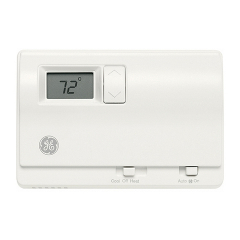
Yolink YS4003-UC Guide

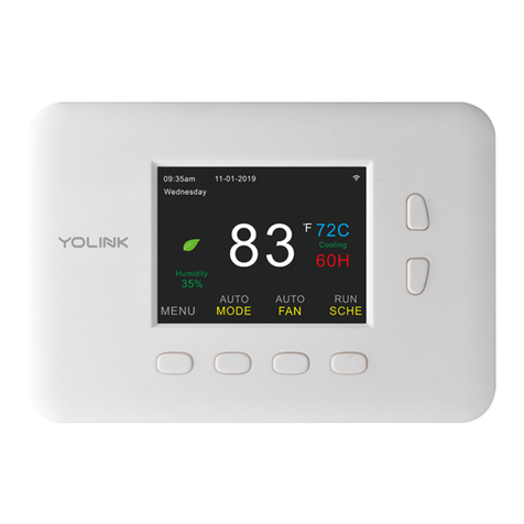
YoLink Thermostat
(Heat Pump Compatible)
YS4003-UC
Installation Manual & User Guide
Rev 1.1
March 29,2023

SECTION TOPIC PAGE
A Welcome! 1
B Before You Begin 2
C What's in the Box? 3
D Install the YoLink App 4
E Add Your Thermostat to the App 6
F Prepare for Installation 8
G Installation 9
H Get to Know Your Thermostat 13
I Set the Cooling or Heating Setpoint 14
J Navigating the Menu System 15
K Schedules: Editing & Copying 16
L Y & Aux Config 19
M Date & Time 20
N Temperature Settings 21
O Display & Sound 22
P Factory Reset 23
Q App Functions: Device Screen 24
R App Functions: Device Details Screen 26
S Automation 28
T Voice Assistants & Integrations 29
U Troubleshooting 30
V CE Mark Warning 31
W FCC Statement 32
X 1-Year Warranty 33
Y Warnings 33
Z Contact Us & Customer Support 34
TABLE OF CONTENTS

Congratulations on the purchase of your YoLink Thermostat!
When connected to the internet via one of our hubs, you can
manage and control your thermostat remotely, including
changing the set temperature, the mode and schedule. The
YoLink Thermostat is the perfect choice if you travel, own a
vacation home, business or rental property, or simply want
the peace of mind of a smart thermostat with 24/7 remote
access and supervision.
We appreciate you trusting YoLink for your smart home &
automation needs. Your 100% satisfaction is our goal. If you
experience any problems with your installation, with our
products or if you have any questions that this manual does
not answer, please contact us right away.
See the Contact Us section for more info.
Thank you!
Eric Vanzo
Customer Experience Manager
Welcome!
A
User Guide Conventions
To assure your satisfaction with your purchase, please read
this user guide we have prepared just for you. The following
icons are used to convey specific types of information:
Very important information (can save you time!)
1
Good to know info but may not apply to you
Mostly unimportant (it’s ok to breeze past it!)

Before you begin installation, please note, the Thermostat
requires a C (Common) wire. It will not function without a C
wire. If the thermostat location does not have a C wire, a new
C wire, or a C wire adapter, must be installed. Please contact
us for additional information and technical support on this
topic.
Please also note, your smart Thermostat connects to the
internet via one of our hubs (original YoLink Hub or the
SpeakerHub), and it does not connect directly to your WiFi or
local network. In order for remote access to the Thermostat
from the app, and for full-functionality, a hub is required.
Otherwise, your Thermostat will have limited functionality with
no remote access. Please contact us for additional information
on this topic.
Before You Begin
B
2
This thermostat works with common single-stage 24 volt
systems such as forced air, hydronic, heat pump, oil, gas, and
electric. It will not work with millivolt systems, such as a gas
fireplace, or with 120/240 volt systems such as baseboard
electric heat.
Need Help?
Please contact us via the Contact Us section of this user
guide, for assistance, before returning your Thermostat.

ThermostatQuick Start Guide
Mounting Plate
(“Back Plate”)
Screws (2)
Drywall Anchors (2)
xxxxxx
xxxxxx
xxxxxx
xxxxxx
xxxxxx
xxxxxx
Wire Labels
What’s in the Box?
C
3

Retain your username and password in a secure location
If you encounter an error message attempting to create
an account, disconnect your phone from WiFi, and try
again, connected only to the cellular network
Apple phone/tablet
iOS 9.0 or higher
Android phone/tablet
4.4 or higher
Install the YoLink App
D
If you are new to YoLink, please install the app on your phone or
tablet, if you have not already. Otherwise, please proceed to part
E.
Scan the appropriate QR code below or find the “YoLink app” on
the appropriate app store.
Open the app and tap Sign up for an account. You will be
required to provide a username and a password.
Follow the instructions, to set up a new account
Allow notifications, if prompted.
1
4

Install the YoLink App, Continued
5
. You will
D
QR code scanner icon
You will immediately receive an email from
no[email protected] with some helpful information. Please
mark the yosmart.com domain as safe, to ensure you receive
important messages in the future.
2
Log in to the app using your new username and password. The
app opens to the Favorite screen, as shown. This is where your
favorite devices will be shown. You can organize your devices by
room, in the Rooms screen, later.
3
Tap Add Device (if shown) or tap the scanner icon
3

XXX
6
Add Your Thermostat to the App
E
Approve access to the camera, if requested. A viewfinder will be
shown on the app.
4
Hold the phone over the QR code (on the rear of the thermostat)
so that the code appears in the viewfinder. If successful, the Add
Device screen will be displayed
5
Refer to Figure 1 on the next page. You can edit the name of the
Thermostat, and assign it to a room, if desired. Tap the Favorite
heart icon to add this device to your Favorites screen. Tap Bind
device
6

Approve access to your phone’s camera, if requested.)
Hold the phone over the QR code (on the underside of
the hub) so that the code appears in the viewfinder. If
9
Figure 1 Figure 2
If successful, close the Device Bound pop-up message by tapping
Close
7
Tap Done as shown in Figure 2.
8
If this is your first YoLink system, please visit our product support
area at yosmart.com for an introduction to the app, and for
tutorials, videos, and other support resources.
Add Your Thermostat to the App, Cont.
E
7
Ensure your YoLink Hub or SpeakerHub is setup and online before
proceeding to the next step.
9

Prepare for Installation
F
The following items may be required for the installation of
your Thermostat:
Medium Phillips Screwdriver Small Slotted Screwdriver
Pencil
Level
Alternative Mounting Hardware
Drill with Drill Bits Multimeter
8

Installation
G
Please Note: This installation manual assumes the Thermostat
is replacing an existing thermostat. For new installations,
please disregard references to the existing thermostat, etc.
Referring to the chart below, match up your thermostat wires with
their matching screw terminal on the Thermostat terminal strip.
1
Note #2: The Thermostat is not compatible with multi-speed cooling, two or
second-stage cooling or heating.
Note #3: The Thermostat does not use an outdoor temperature sensor. This is
an optional feature used for heat pump lockout, based on outside
temperature. As there is no automatic lockout with the Thermostat, users are
required, to avoid possible compressor damage, to not run the air conditioner
if outside temperatures are below 50°F (10°C).
If your existing thermostat has additional wires that do not appear
to correspond with any of these wire designations, please contact
Contact Us page of this manual (see the last page).
THERMOSTAT
TERMINAL TYPICAL WIRE
DESIGNATIONS
FUNCTION
REMARKS
Y Y
HEAT AND COOL MODE
G G
FAN RELAY
W W, O/B
PRIMARY HEATING
AUX AUX, or E
EMERGENCY HEAT
C C or COM
24VAC COMMON
SEE NOTE #1
R R, RC, RH
24VAC POWER
Y1, Y2
MULTI
-SPEED OR SECOND STAGE COOL
SEE NOTE #2
W2
SECOND STAGE HEAT
SEE NOTE #2
OAT
OUTSIDE AIR TEMPERATURE
SEE NOTE #3
SRTN, OAT RETURN
OUTSIDE AIR TEMPERATURE
SEE NOTE #3
Note #1: Confirm the presence of a C wire, or one labeled COM or
COMMON. The Thermostat will not function without a C wire (or C wire
adapter, as previously noted).
9

Installation, Continued
G
CAUTION: To prevent personal injury and damage to
property, always remove power to the thermostat by turning
off the HVAC equipment at the circuit breaker panel, prior to
performing any steps related to connecting or changing the
thermostat wiring!
Turn off power, as required, to ensure there are no energized
wires at the thermostat location.
2
Before making any changes to the thermostat wiring, it is
important to identify the individual wires and their functions.
Using the supplied labels (or masking tape, etc.) label each wire
with the same identifier that is on the existing thermostat (“C”, “R”
etcetera). It may also help to have a picture of the wiring on the
existing thermostat, in case a label falls off or if you need to
reinstall the existing thermostat.
3
Remove your existing thermostat and back plate from the wall.
Use care to not allow the cable to fall into the hole in the wall!
4
Mount the new back plate to the wall, using the appropriate
method, for example, with the supplied drywall anchors. Position
the plate, to cover the hole in the wall, and check the level of the
plate, as needed. Do not overtighten the mounting screws, as this
will warp the back plate, adversely impacting the thermostat
operation.
5
10

Installation, Continued
G
Terminate each conductor on its respective screw terminal. You
will need to loosen each screw terminal, first. When finished,
gently tug on each wire, to ensure a good connection.
6
Refer to the rear of the Thermostat. Set the HP/GAS slide switch
to HP for heat pump systems, otherwise to GAS. You can change
the switch setting with a small screwdriver, pencil or similar object.
7
If you set the HP/GAS switch to HP
, set the O/B slide switch to O
for energizing the reversing valve on cooling (hot climates) or B
for energizing the reversing valve on heating (cold climates)
operation.
If you set the HP/GAS switch to GAS
, the valve will only energize
for heating.
8
Gently push the thermostat down onto the back plate. You may
hear an audible click, as it snaps into place. Observe the rear
thermostat sides, near the wall, to ensure there are no uneven
gaps between the plate and the thermostat. Gently tug on the
thermostat, to ensure it does not come loose.
9
11

Installation, Continued
G
Turn on power to the unit. The Thermostat display should
immediately turn on. If not, doublecheck your wire terminations,
power-off the unit and correct any mistakes as needed. If the
thermostat still does not turn on, refer to the Troubleshooting,
section U.
10
12

Please take a moment to familiarize yourself with your new
Thermostat.
Get to Know Your Thermostat
H
4 5 6
7
8
9
10
11
12
131415
16171819
20
21
3
2
1
1) Current day of the week
2) Current time of day
3) Current Date
4) Current temperature
5) Fahrenheit/Celsius indicator
6) Connection status (white if
connected, red if disconnected)
7) Cooling set point
8) Temperature up button
9) Status (“Cooling” if in cooling
mode, “Heating” if in heating
mode)
10) Temperature down button
11) Heating set point
12) Schedule status (“RUN” if running
on a schedule, “HOLD” if not
running on a schedule
13) Schedule button (press to activate
or deactivate schedules)
14) Fan status (“AUTO” if fan will run on
demand, “ON” if the fan is on (running)
15) Fan button (press to switch the fan
between Auto and On mode
16) Mode button (press to switch
between system modes: Auto, Heat,
Cool, Off)
17) Mode status (“AUTO” if cooling or
heating automatically, “HEAT” if only
heating is running, “COOL” if only
cooling is running
18) Menu button (press to access the
Thermostat’s menu system)
19) Menu indicator
20) Current humidity level (%)
21) ECO (Energy Conservation
Operation) Leaf appears if in ECO mode
13

72
DONE
BACK
Cool Temp
Tap to
raise the
setpoint
Tap to
lower the
setpoint
Tap to save
your setpoint
Tap to exit
without saving
First, tap the up or down button. Tap the appropriate buttons, to
adjust the setpoint up or down.
1
When finished, tap the DONE button. To exit this process, tap the
BACK button.
2
To avoid frequently turning the heating or cooling on and off,
a 6 degree Fahrenheit/3 degree Celsius default, minimum, gap
between the cooling and heating set points exists in all modes.
Set the Cooling or Heating Setpoint
I
14

ENTERBACK
Menu Selection
Tap to
navigate
up
Tap to
navigate
down
Tap to save
your changes
Tap to exit
without saving
First, tap the MENU button.
1
Use the UP and DOWN buttons to navigate up or down the
menu items
2
Use the ENTER button to select an item.
3
Tap DONE when finished, or tap BACK to exit without saving
4
Schedules
Y & AUX Config
Date & Time
Temperature
Display & Sound
Navigating the Menu System
J
15

DONE NEXT
Mon Schedule
One day of the week is displayed at a time. The current day is
identified at the top of the screen, abbreviated Mon, Tue,
Wed, etcetera. (To navigate to other days, tap the NEXT
button.)
Each day has up to four unique temperature adjustment
events, labeled Wake, Leave, Return and Sleep.
Each event has a heat and a cool setpoint. The current mode
of the thermostat determines which setpoint is applied to the
current schedule.
You can schedule an entire day, then copy that schedule to
other similar days, for identical schedules on those days, or as
a starting point for a similar schedule, that you can edit to suit
Use the left and right arrow buttons to navigate through each
item that can be edited (hour, minute, heat setpoint, cool
setpoint). Scrolling starts over at the first item after passing
the last item (“Copy to”)
Schedules: Editing & Copying
K
This section demonstrates viewing and editing the schedule from
the thermostat. See section Q for viewing/editing from the app.
The Scheduling Submenu:
+
-
Time H C
Wake
Leave:
Return:
Sleep:
06:00 AM
08:00 AM
05:00 PM
11:00 PM
70
60
64
60
75
80
75
80
16

DONE NEXT
Mon Schedule
Schedules: Editing & Copying
K
+
-
Time H C
Wake
Leave:
Return:
Sleep:
06:00 AM
08:00 AM
05:00 PM
11:00 PM
70
60
64
60
75
80
75
80
17
To edit a schedule, tap MENU. Navigate to Schedules, tap ENTER
1
To change the selected day, tap the NEXT button until the correct
day is displayed.
2
Use the left and right arrow buttons to navigate between items.
Selected items are identified by green colored text. Use the + and
–buttons to change the item valve up or down. When correct,
navigate to the next item using the left or right arrow buttons.
3
You can give edit each day of the week or you can copy the
schedule of one day over to another day. This is explained in the
next section.
4

BACK COPY
Copy Schedule To
Schedules: Editing & Copying
K
Y
Sun:
Tue:
Thu:
N
N
N
18
After editing a day of the week that you wish to copy to another
day, select Copy To. Tap the COPY button. A screen similar to the
one below is displayed, showing the six other days of the week.
Use the left and right arrow buttons to scroll between the days of
the week. Each day is initially marked with an “N” which indicates
it will not be updated with your copied schedule. Use the Y button
to mark each day you wish to be updated with the copied
schedule. After your Y/N selections have been made, tap the
COPY button.
1
N
Mon:
Wed:
Fri:
N
N
N
2
At this time, you can review your updated schedule, using the left
and right arrow buttons. If finished editing, tap DONE to exit
Schedules, then BACK to exit the menu system.
Table of contents
Other Yolink Thermostat manuals
Popular Thermostat manuals by other brands
Honeywell
Honeywell T834C installation instructions
Honeywell
Honeywell T7512B installation instructions

Drayton
Drayton RF701 installation instructions
Honeywell
Honeywell INNCOM E529 Wiring guide
Honeywell Home
Honeywell Home T10 Pro RedLINK How to use
Honeywell
Honeywell Deluxe Programmable Thermostat Operation user's manual
