manuals.online logo
Brands
  1. Home
  2. •
  3. Brands
  4. •
  5. Salus
  6. •
  7. Thermostat
  8. •
  9. Salus STP1 User manual

Salus STP1 User manual

Other Salus Thermostat manuals

Salus 091FLRF User manual

Salus

Salus 091FLRF User manual

Salus RT520 User manual

Salus

Salus RT520 User manual

Salus RT520 User manual

Salus

Salus RT520 User manual

Salus HTR230 User guide

Salus

Salus HTR230 User guide

Salus RT510BC User manual

Salus

Salus RT510BC User manual

Salus ST620 Owner's manual

Salus

Salus ST620 Owner's manual

Salus HTRP-RF(50) User manual

Salus

Salus HTRP-RF(50) User manual

Salus EP110 User manual

Salus

Salus EP110 User manual

Salus SQ605RF User manual

Salus

Salus SQ605RF User manual

Salus RT310SPE User manual

Salus

Salus RT310SPE User manual

Salus VS05 User manual

Salus

Salus VS05 User manual

Salus Quantum WQ610 User manual

Salus

Salus Quantum WQ610 User manual

Salus WBNTSQ61024 Quantum User manual

Salus

Salus WBNTSQ61024 Quantum User manual

Salus QUANTUM SQ610RF User manual

Salus

Salus QUANTUM SQ610RF User manual

Salus RT510RF User manual

Salus

Salus RT510RF User manual

Salus TS600 User manual

Salus

Salus TS600 User manual

Salus VS20WRF User manual

Salus

Salus VS20WRF User manual

Salus CT100 User manual

Salus

Salus CT100 User manual

Salus RT310 User manual

Salus

Salus RT310 User manual

Salus RT310RF User manual

Salus

Salus RT310RF User manual

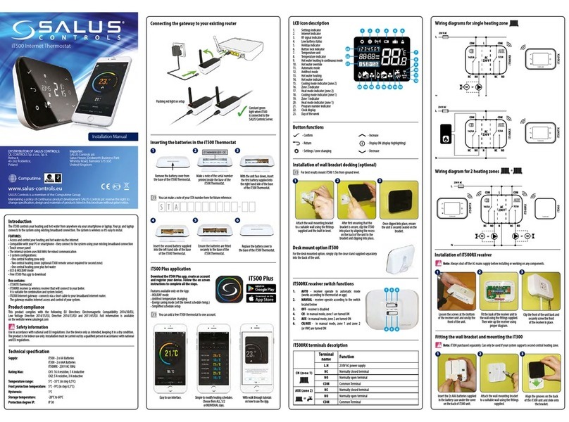
Salus iT500 User manual

Salus

Salus iT500 User manual

Salus RT510BC User manual

Salus

Salus RT510BC User manual

Salus rt505tx User manual

Salus

Salus rt505tx User manual

Salus VS20WRF User manual

Salus

Salus VS20WRF User manual

Popular Thermostat manuals by other brands

Full Gauge TIC-17C product manual

Full Gauge

Full Gauge TIC-17C product manual

Imit Chronomix S manual

Imit

Imit Chronomix S manual

ChiliTec ST-35 ana instruction manual

ChiliTec

ChiliTec ST-35 ana instruction manual

Azel D-500 user guide

Azel

Azel D-500 user guide

Honeywell Chronotherm III owner's manual

Honeywell

Honeywell Chronotherm III owner's manual

Charmeg MP-R user manual

Charmeg

Charmeg MP-R user manual

dixell WING XW40LS Installing and operating instructions

dixell

dixell WING XW40LS Installing and operating instructions

Network Thermostat NetX X7C-WIFI Installation and programming manual

Network Thermostat

Network Thermostat NetX X7C-WIFI Installation and programming manual

Radio Thermostat CT80 Operation guide

Radio Thermostat

Radio Thermostat CT80 Operation guide

HAI Omnistat RC-120 installation manual

HAI

HAI Omnistat RC-120 installation manual

Lennox iComfort E30 Installation and setup guide

Lennox

Lennox iComfort E30 Installation and setup guide

Lux Products PSD011Ba Installation and operating instructions

Lux Products

Lux Products PSD011Ba Installation and operating instructions

Computherm Q20 operating instructions

Computherm

Computherm Q20 operating instructions

Heatmiser neoStat user manual

Heatmiser

Heatmiser neoStat user manual

Mars HEAT CONTROLLER IR Wireless Thermostat user manual

Mars

Mars HEAT CONTROLLER IR Wireless Thermostat user manual

LUX LP0511D user manual

LUX

LUX LP0511D user manual

Saswell SAS920XWHB-7-S-RF User manual and warranty card

Saswell

Saswell SAS920XWHB-7-S-RF User manual and warranty card

Aircalo TFP1-ET85P2 operating manual

Aircalo

Aircalo TFP1-ET85P2 operating manual

manuals.online logo
manuals.online logoBrands
  • About & Mission
  • Contact us
  • Privacy Policy
  • Terms and Conditions

Copyright 2025 Manuals.Online. All Rights Reserved.

Manual STP1 pumps
thermostat
Operating principle
The thermostat is designed to control water
circulation pump C.O. The task of the thermostat
is switching on the pump if the temperature
exceeds required value, and disable it when the
boiler cools down (due to extinction).Prevents
unnecessary operation of the pump, which saves
electric energy (savings, depending on the degree
of utilization of the boiler, reaching up to 60%) and
extend pump life. This increases the reliability
and decrease costs associated with the operation.
The temperature pump start is controlled
potentiometer (range 10˚C-90˚C). The pump stops
when the actual temperature drops by 5˚C below
the temperature set point (potentiometer set).
Start and stop the pump after about 30 seconds.
Prevents the constant switching of the pump in
case of rapid changes temperature.
The thermostat has two switches. The first one is
used to switching on the thermostat (this is
indicated by the glowing red LED’s). The second is
used for manual pump operation (indicated by
green). Green LED indicates the operation of the
pump with automatic control of pump. The
regulator has a protection in the form of reusable
polymer fuse (inside the housing of the plate).
Connecting the pump C.O.
1. To terminal wire yellow - green
2. To terminal Nwire blue
3. To terminal Lwire brown
WIRING DIAGRAM
1. Potentiometer
2. Temperature sensor
3. Manually switch the pump mode
4. The power switch
5. Power cord
6. Pump power cord
7. LED for operation of the pump
8. LED indicating power on.
DANGER: Do not Touch electrical Components or
circuits. Isolate mains electricity supply before
starting any work and observe all relevant safety
precautions. Installation should be made by a
person with adequate electrical power!
TECHNICAL DATA
Temperature range
10°C - 90°C
Hysteresis
5°C
Supply voltage
230/50Hz +/-10%
Power
<2W
Temperature operating
-10°C-50°C
Section of connecting
cables
3x0,75mm
Sensor cable length
1,2m\
Output load current
180W
Dimensions
(72x50x132)
Warranty
Salus Controls warrants that this product will be
free from Any defekt In materials or workmanship,
and shall perform in accordance with its
specification, for a period of two years from the
date of installation. Salus Controls sole liability for
breach of this warranty will be (at its option) to
repair or replace the defective product.
Customer Name:…………………………………………………………..
Customer Address:………………………………………………………..
Post Code:…………………………………………………………………
Tel No:………………………………………………………………………..
Email:……………………………………………………………………….
Engineers Company:………………………………………………….
Tel No:……………………………………………………………………..
Email:……………………………………………………………………….
Installation Date:…………………………………………………..
Engineers Name:…………………………………………………..
Engineers Signature:……………………………………………..
SALUS Controls plc
Dodworth Business Park South,
Whinby Road, Dodworth, Barnsley,
S75 3SP UK