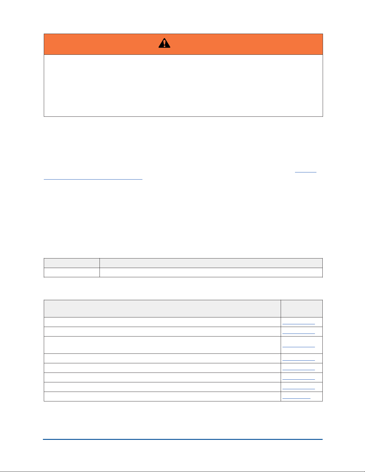
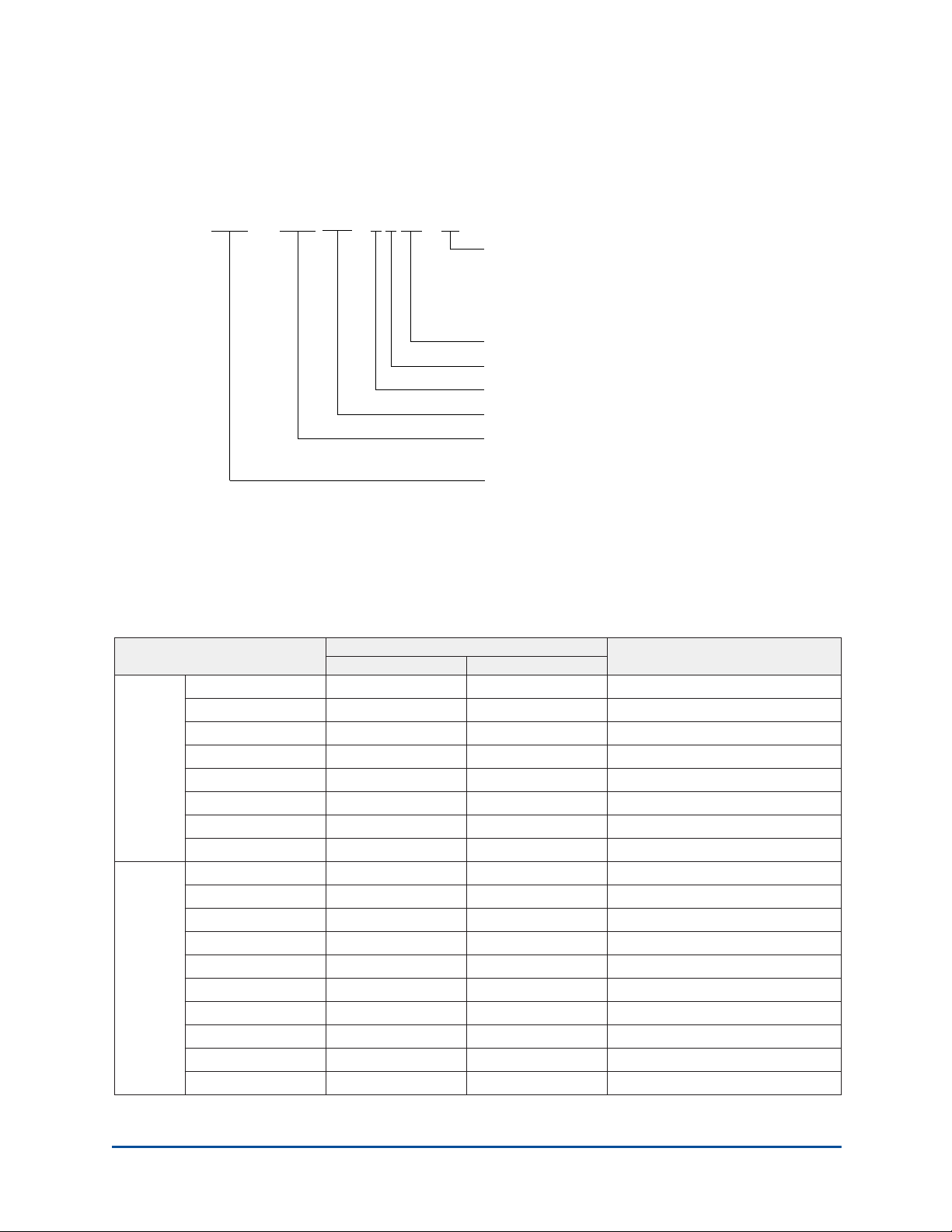
Table 1: VSD part numbers and descriptions
Part number
Model 60 Hz 50 Hz Description
VSD419T-50 371-03789-X05 Factory Pack, YT Base Model
VSD419K-50 371-03789-X06 Factory Pack, YK Base Model
VSD419TFT-50 371-03789-X07 Factory Pack, YT Filter Model
VSD419KFT-50 371-03789-X08 Factory Pack, YK Filter Model
VSD419RT-50 371-03789-X15 Retrofit, YT Base Model
VSD419RK-50 371-03789-X16 Retrofit, YK Base Model
VSD419RTFT-50 371-03789-X17 Retrofit, YT Filter Model
VSD419RKFT-50 371-03789-X18 Retrofit, YK Filter Model
W-VSD419K-50 371W06431-X06 Factory Pack, YK Base Model
W-VSD419KFT-50 371W06431-X08 Factory Pack, YK Filter Model
W-VSD419T-50 371-05395-X05 Factory Pack, YT Base Model
W-VSD419K-50 371-05395-X06 Factory Pack, YK Base Model
W-VSD419TFT-50 371-05395-X07 Factory Pack, YT Filter Model
W-VSD419KFT-50 371-05395-X08 Factory Pack, YK Filter Model
W-VSD419RT-50 371-05395-X15 Retrofit, YT Base Model
W-VSD419RK-50 371-05395-X16 Retrofit, YK Base Model
W-VSD419RTFT-50 371-05395-X17 Retrofit, YT Filter Model
419 HP
400 VAC
W-VSD419RKFT-50 371-05395-X18 Retrofit, YK Filter Model
VSD419T-68 371-03789-X25 Factory Pack, YT Base Model
VSD419K-68 371-03789-X26 Factory Pack, YK Base Model
VSD419TFT-68 371-03789-X27 Factory Pack, YT Filter Model
VSD419KFT-68 371-03789-X28 Factory Pack, YK Filter Model
VSD419RT-68 371-03789-X35 Retrofit, YT Base Model
VSD419RK-68 371-03789-X36 Retrofit, YK Base Model
VSD419RTFT-68 371-03789-X37 Retrofit, YT Filter Model
VSD419RKFT-68 371-03789-X38 Retrofit, YK Filter Model
W-VSD419K-68 371W06431-X26 Factory Pack, YK Base Model
419 HP
415 VAC
W-VSD419KFT-68 371W06431-X28 Factory Pack, YK Filter Model
VSD424T-58 371-04881-X01 Factory Pack, YT Base Model
VSD424K-58 371-04881-X02 Factory Pack, YK Base Model
VSD424TFT-58 371-04881-X03 Factory Pack, YT Filter Model
VSD424TFK-58 371-04881-X04 Factory Pack, YK Filter Model
VSD424RT-58 371-04881-X11 Retrofit, YT Base Model
VSD424RK-58 371-04881-X12 Retrofit, YK Base Model
VSD424RTFT-58 371-04881-X13 Retrofit, YT Filter Model
424 HP
575 VAC
VSD424RTFK-58 371-04881-X14 Retrofit, YK Filter Model
Liquid-Cooled OptiSpeed Compressor Speed Drive10