Installation Instructions
• Connect the duct connections to unit supply and return air ducts.
• Refer to GA drawing for unit supply and return duct connection sizes and locations.
• Use canvas connection between unit & supply air duct to avoid the transmission of vibration to the duct.
• Don't run the unit without filter on return air side.
• Avoid abnormal duct size increases and reductions. It can adversely affects air and cooling performance.
• When electrical heater is installed, use fireproof canvas (or similar heat resistance material) between duct & unit
discharge connection.
• Do the proper duct sizing for air quantity (L/s or cfm) recommended at various External Static Pressures.
• All ducting should be insulated properly to avoid heat transfer.
• All ducts should be secured properly to building structural opening should be sealed properly to avoid any air
leakage or condensation.
• All main branch ducts (without 90° elbow) should be acoustically lined up to min. 10 ft length with the help of all
perforated sheet & fiber glass insulation of recommended density & thickness.
• Ensure Room thermostat fixed at proper location, sensing return air or room temperatures and set the thermostat
not less than 70° F.
Indoor Units
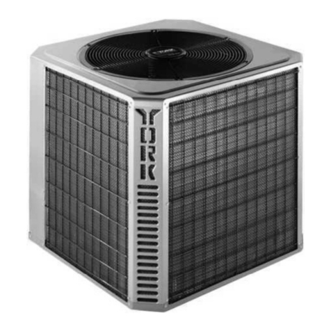
Outdoor Unit Location and Mounting
•
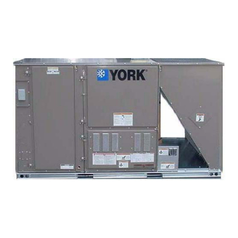
• Unit must be lifted by 2” pipe hook rigging sling in base rail, use spreader bar to prevent the sling from damaging
the unit.
• A minimum clearance of 1 m on serviceable side, 300 mm for air inlets on all sides and 1.5 m for air discharge (unit
top) is required.
• The unit must be located outdoor only and cannot be connected to duct work.
• The metal parts of the unit if subjected to salt spray, fog or mist in seacoast areas could lead to rapid
corrosion/oxidation and may lead to premature failure.
• Interconnecting tubing.
• Vapor and Liquid lines.
• Keep all lines sealed until connection is made.
• Make connections at the indoor coil first.
• In dual circuit units, ensure Liquid & Suction tubes at indoor & out door units are brazed to
corresponding systems.
• Connect the filter drier and sight glass at the liquid line in the flow direction marked on the components.
• Perform the Leak check at all the brazed and flare joints.
• Perform system Evacuation up to 200 microns.
• Factory charged unit is sufficient for 25 feet of interconnecting tubing.
• Maximum length of lines
• The maximum equivalent length of interconnecting line is 200 feet. Always use the shortest length
possible with minimum number of bends.
• If the application call for more length of piping, please contact our sales officer.
• Sizing
Please refer the Guideline for inter connecting piping.
Consult local building codes or ordinances for special installation requirements.
Locating Unit
COMMERCIAL DUCTED SPLITS 07
