JOHNSON CONTROLS 5
FORM 160.00-O4
ISSUE DATE: 07/31/2019
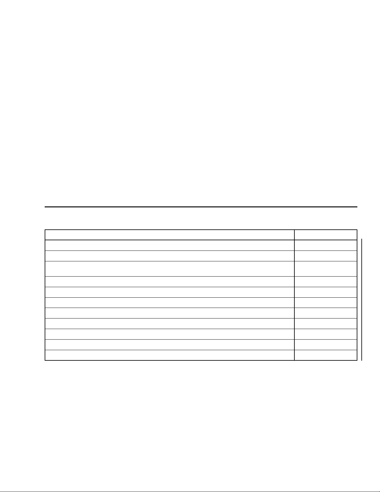
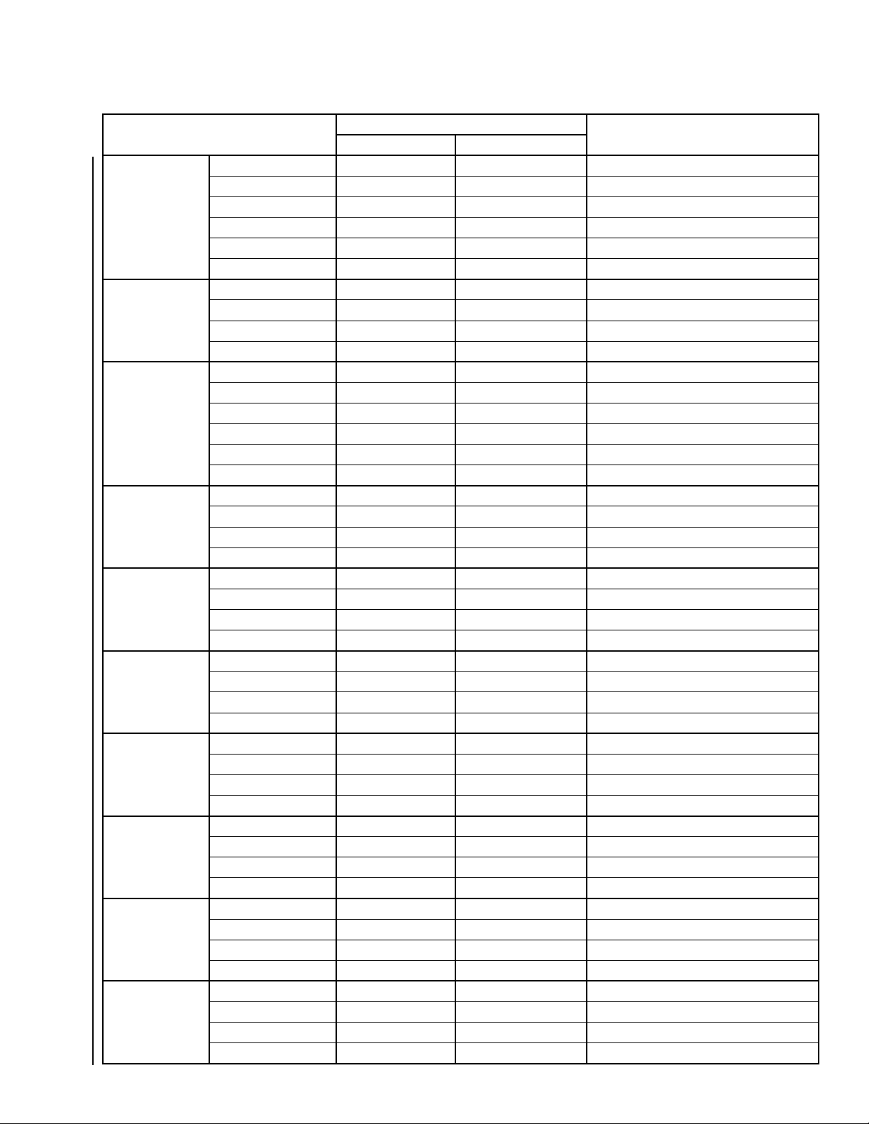
MODEL PART NUMBER DESCRIPTION
60 HZ 50 HZ
292 HP
415 VAC
VSD292T-68 371-03700-X21 Factory Pack, YT Base Model
VSD292K-68 371-03700-X22 Factory Pack, YK Base Model
VSD292TFT-68 371-03700-X25 Factory Pack, YT Filter Model
VSD292KFT-68 371-03700-X26 Factory Pack, YK Filter Model
VSD292RT-68 371-03700-X31 Retrot, YT Base Model
VSD292RK-68 371-03700-X32 Retrot, YK Base Model
VSD292RTFT-68 371-03700-X35 Retrot, YT Filter Model
VSD292RKFT-68 371-03700-X36 Retrot, YK Filter Model
W-VSD292K-68 371W06040-X22 Factory Pack, YK Base Model
W-VSD292KFT-68 371W06040-X26 Factory Pack, YK Filter Model
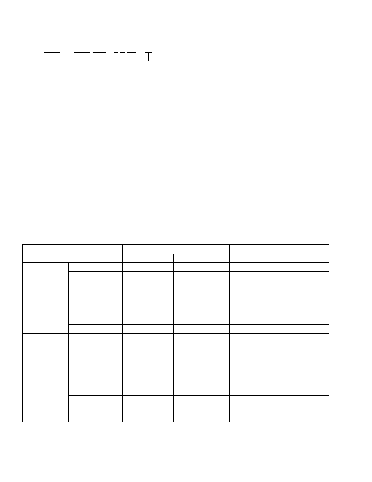
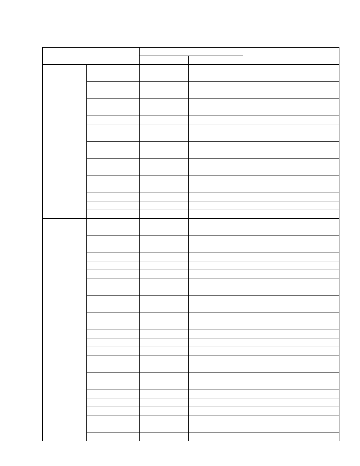
351 HP
460 VAC
VSD351T-46 371-02767-X01 Factory Pack, YT Base Model
VSD351K-46 371-02767-X02 Factory Pack, YK Base Model
VSD351TFT-46 371-02767-X05 Factory Pack, YT Filter Model
VSD351TFK-46 371-02767-X06 Factory Pack, YK Filter Model
VSD351RT-46 371-02767-X11 Retrot, YT Base Model
VSD351RK-46 371-02767-X12 Retrot, YK Base Model
VSD351RTFT-46 371-02767-X15 Retrot, YT Filter Model
VSD351RTFK-46 371-02767-X16 Retrot, YK Filter Model
385 HP
400 VAC
VSD385T-40 371-03789-X21 Factory Pack, YT Base Model
VSD385K-40 371-03789-X22 Factory Pack, YK Base Model
VSD385TFT-40 371-03789-X23 Factory Pack, YT Filter Model
VSD385KFT-40 371-03789-X24 Factory Pack, YK Filter Model
VSD385RT-40 371-03789-X31 Retrot, YT Base Model
VSD385RK-40 371-03789-X32 Retrot, YK Base Model
VSD385RTFT-40 371-03789-X33 Retrot, YT Filter Model
VSD385RKFT-40 371-03789-X34 Retrot, YK Filter Model
419 HP
400 VAC
VSD419T-50 371-03789-X05 Factory Pack, YT Base Model
VSD419K-50 371-03789-X06 Factory Pack, YK Base Model
VSD419TFT-50 371-03789-X07 Factory Pack, YT Filter Model
VSD419KFT-50 371-03789-X08 Factory Pack, YK Filter Model
VSD419RT-50 371-03789-X15 Retrot, YT Base Model
VSD419RK-50 371-03789-X16 Retrot, YK Base Model
VSD419RTFT-50 371-03789-X17 Retrot, YT Filter Model
VSD419RKFT-50 371-03789-X18 Retrot, YK Filter Model
W-VSD419K-50 371W06431-X06 Factory Pack, YK Base Model
W-VSD419KFT-50 371W06431-X08 Factory Pack, YK Filter Model
W-VSD419T-50 371-05395-X05 Factory Pack, YT Base Model
W-VSD419K-50 371-05395-X06 Factory Pack, YK Base Model
W-VSD419TFT-50 371-05395-X07 Factory Pack, YT Filter Model
W-VSD419KFT-50 371-05395-X08 Factory Pack, YK Filter Model
W-VSD419RT-50 371-05395-X15 Retrot, YT Base Model
W-VSD419RK-50 371-05395-X16 Retrot, YK Base Model
W-VSD419RTFT-50 371-05395-X17 Retrot, YT Filter Model
W-VSD419RKFT-50 371-05395-X18 Retrot, YK Filter Model
TABLE 1 - VSD PART NUMBERS AND DESCRIPTIONS (CONT'D)