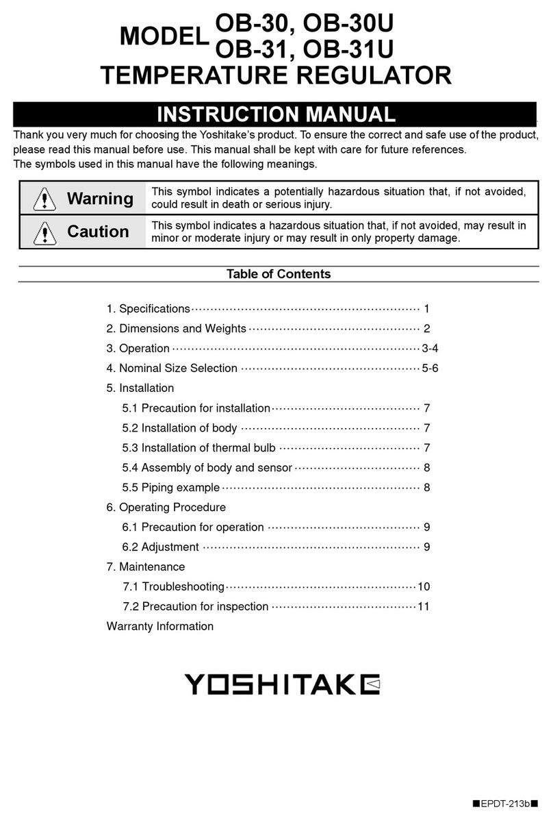
Yoshitake OB-30 User manual

13-1
Temperature Regulator
13

13-2
Step 0 Type/Structure/Features
Please refer to this for type, structure and features of
Temperature Regulator.
Step 1 Selection
Please refer to the ID chart to select the right products
depending on the intended uses. Details are on the
product page.
Step 2 Sizing
Please check the required Cv value from size selection
data on P. -7, or size selection chart on the product
page of each products.
Step 3 Attention for usage

www.yoshitake.jp
13-3
13
Temperature Regulator
What is bellows type Temperature Regulator?
∙ A temperature regulator, that is self-acting, automatically controls the steam/liquid flow, in response to
the temperature changes in the cooled/heated media, and keeps the cooled/heated fluid temperature at a
constant level.
∙ Automatic temperature regulator requires no electricity for operation, so it keeps on operating in case of
electricity failure.
∙ No need for electric construction and temperature can be adjusted just by twisting the handle.
Selection of bellows type Temperature Regulator
For liquid For air
Controls heating fluid
in order to maintain set
temperature.
Controls cooling fluid
in order to maintain set
temperature.
Direct acting type
Pilot type
Direct acting type
Internal pressure
bellows
External pressure
bellows
Use steam or hot water in order to raise the
temperature of heat exchanger and storage
tank.
Use cold water or cooling fluid in order to
cool down the temperature of liquid such as
lubricant oil.
Use steam or hot water in order to raise the
temperature of heat exchanger and storage
tank. It has larger flow capacity than direct
acting type.
·OB-1-OB-6 general purpose type.
Recommended to be used at a place where
the difference between the set temperature
and the ambient temperature is 30˚C or more.
·OB-1-OB-6 “G” type.
Insusceptible to the ambient temperature and
usable even at a place where the difference
between the set temperature and the ambient
temperature is 30˚C or less.
Heating
Cooling
Bellows

www.yoshitake.jp 13-4
13
Temperature Regulator
Step
0
Features of Direct Acting Type <OB-30>
For small heat exchanger, HVAC and
plating apparatus.
Application
Red or Blue handle
Thermal bulb (Gas filled type)
High durability and sealing
function
Dial
Pressure balancing
mechanism
Light and compact
Red for heating and blue for cooling.
Easily adjust the temperature by
handle without any tool.
Thermal bulb can be installed in any
position because the temperature is
sensed by sealing gas. It is especially
recommended to the food processing
industry.
Stainless steel and PTFE materials
are used for the valve disc, which
ensures high durability and sealing
function.
All sizes of both heating and cooling
type use same thermal bulb. It
is available with stainless steel
(SUS304) made thermal well as an
option.
2 m is the standard of capillary tube.
3 m and 5 m is also available.
For checking the set temperature.
Equipped with two bellows called
balance bellows which ensure stable
temperature regulation, the OB-
30 is not affected by inlet pressure
fluctuation.
Enables easy piping construction.
OB-30 OB-30U

www.yoshitake.jp
13-5
13
Temperature Regulator
Temperature Regulator ID-Charts
Model Type Fluid Material
Max.
Press.
(MPa)
Max.
Temp.
(˚C)
Connection
Size Feature Page
OB-30
External
pressure
bellows
Steam
CAC406
1.0
185°C
JIS Rc 15-25A
·
Heating (red
handle)
· Low-leakage
designed single
seat valve
13-11
Hot water 1.7
OB-30U
Steam 1.0
JIS Rc
(union joint)
15-25A 13-11
Hot water 1.7
OB-31
External
pressure
bellows
Cold water,
Refrigerant
CAC406 1.7 185°C
JIS Rc 15-25A
·
Cooling (blue
handle)
· Low-leakage
designed single
seat valve
13-11
OB-31U JIS Rc
(union joint)
15-25A 13-11
OB-2000
External
pressure
bellows
Steam FCD450
2.0
1.0 for
JIS10K
220°C
JIS Rc 15-50A · Heating
· Pilot type
·
Large flow capacity
13-14
JIS 10KFF
JIS 20KRF 15-100A
OB-1
Internal
pressure
bellows
Steam,
Hot water CAC406 0.7 180°C JIS Rc
(union joint)
15-40A · Heating 13-17
OB-1G
External
pressure
bellows
15-40A
·
Low temperature
heating
13-17
OB-2
Internal
pressure
bellows
Steam,
Hot water FC200 0.2-0.7* 180°C JIS 10KFF
15-150A
·
Heating
13-20
OB-2G
External
pressure
bellows
15-125A
·
Low temperature
heating
13-20
* Max. pressure depends on size. For details please refer to P. -20.
TEMPERATURE REGULATORS Control ID-Charts

www.yoshitake.jp 13-6
13
Temperature Regulator
Model Type Fluid Material
Max.
Press.
(MPa)
Max.
Temp.
(˚C)
Connection
Size Feature Page
OB-3
Internal
pressure
bellows
Cold water,
Refrigerant
CAC406 0.7 180°C JIS Rc
(union joint)
15-40A · Cooling 13-23
OB-3G
External
pressure
bellows
15-40A ·
Low temperature
cooling
13-23
OB-4
Internal
pressure
bellows
Cold water,
Refrigerant
FC200 0.2-0.7 * 180°C JIS 10KFF
15-150A · Cooling 13-26
OB-4G
External
pressure
bellows
15-125A ·
Low temperature
cooling
13-26
OB-5
Internal
pressure
bellows
Steam,
Hot water
CAC406 0.5 180°C JIS Rc
(union joint)
15-25A
·
Low-leakage
designed single
seat valve
13-29
OB-6
External
pressure
bellows
FC200 0.5 180°C JIS 10KFF 15-25A
·
Low-leakage
designed single
seat valve
13-31
* Max. pressure depends on size. For details please refer to P. -26.
Step
1

www.yoshitake.jp
13-7
13
Temperature Regulator
Step
2
Nominal Size Selection for Temperature Regulator
Calculation formula for Cv value
(1) For steam
When
P2> P1
2Cv = Wk
138 ΔP(P1+ P2)
When
P2P1
2Cv = Wk
120P1
(2) For liquid
Cv = 0.365V G
ΔP
W : Max. flow rate of steam [kg/h]
P1 : Inlet pressure [MPa ∙ A]
P2 : Outlet pressure [MPa ∙ A]
ΔP : P1 - P2[MPa]
k : 1 + 0.0013 x {superheated steam temperature [˚C]
– saturated steam temperature [˚C]}
G : Specific gravity (against water in the case of fluid)
V : Max. flow rate of fluid [m3/h]
Cv : Cv value of each nominal size
Cv value table
Nominal size
Model 15A 20A 25A 32A 40A 50A 65A 80A 100A 125A 150A
OB-30, 31 0.8 1 1.2 − − − − − − − −
OB-2000 5.0 7.2 10.9 14.3 18.8 32 54 70 108 − −
OB-1, 1G 2 2 4 7 10 − − − − − −
OB-2, 2G 2 2 4 7 10 14 21 27 42 72 94
OB-3, 3G 2 2 4 7 10 − −−−−−
OB-4, 4G 2 2 4 7 10 14 21 27 42 72 94
OB-5 1 1 2 − − − −−−−−
OB-6 1 1 2 − − − − − − − −
Point to remember when selecting the size
∙ If system has small capacity and seat leakage become a problem, select single valve type such as OB-30 Series, OB-5 or OB-6.
∙ Differential pressure between inlet and outlet of temperature regulator should be 0.05 MPa in principle. It is recommended that inlet
pressure be 0.2-0.3 MPa to obtain the best performance of the temperature regulator and its longer product life.

www.yoshitake.jp 13-8
13
Temperature Regulator
Step
3
Guidelines for Temperature Regulator OB-30 Series
OB-30 Series
Precautions during Installation (Body and sensor are packed separately).
∙ Installation of body
1. Be sure not to lose the bellows follower (attached
component).
2. Install the temperature regulator perpendicularly to
horizontal piping with the handle facing upward.
3. Check the direction of the temperature regulator
so that the fluid flowing and the arrow marked on
the body are in the same direction.
4.
Be sure to install pressure gauge, strainer and bypass
line to the piping (see “Piping Example” below).
5. The pressure of heating fluid should be reduced
with a pressure reducing valve if it exceeds the
maximum pressure.
6. Completely discharge the fluid inside the piping
and close the stop valves installed at before and
after the temperature regulator before stopping
operation of the product for an extended period.
7. Be sure to remove foreign matter from the piping
through the bypass line at the starting before
operating the temperature regulator.
∙ Installation of thermal bulb
1. Although the thermal bulb can be mounted in
any posture, make sure that more than 3/4 of its
total length is in direct contact with the fluid to be
heated or cooled.
2. Screw on bushing first, then use washer of
packing to secure the thermal bulb.
3. The bend radius of the capillary tube should be
more than 40 mm. Avoid bending at a sharp angle,
twisting or pulling it with force.
4. Install the thermometer close to the thermal bulb.
5. When inserting the thermal bulb into the piping for
temperature detection, it should be installed at a
point where the circulation is best.
∙ Assembly of body and thermal bulb
Install the bellows follower into the bellows at thermal
bulb with its flat surface facing downward and then
screw it into the lower surface of the body by the
ring. During the assembly, it makes assembly easy to
loosen the handle to direction of the “Low” position.
Becareful not to lose bellows follower. It may cause
malfunction.
Body
Ring
Bellows
Bellows follower
Piping example
∙ OB-30 ∙ 30U (for heating) ∙ OB-31 ∙ 31U (for cooling)
Steam
Strainer Storage tank
Hot water
Capillary tube
Thermal bulb
Thermometer
Model OB-30
Temperature
regulator
Safety relief valve
Pressure
gauge
Strainer
Heating coil
Bypass
Condensate
Trap
Water
Air
Air
Thermal
bulb
After cooler
Bypass
Water
Water
Capillary tube
Strainer
Stop
valve Stop valve
Model OB-31
Temperature regulator

www.yoshitake.jp
13-9
13
Temperature Regulator
Guidelines for Temperature Regulator OB-2000 Series
OB-2000 Series
Precautions during Installation OB-2000 series
∙ Installation of main valve
1. Be sure that there are no foreign matters or scales
inside the piping before plumbing.
2. Install the temperature regulator perpendicularly to
horizontal piping with the handle facing upward.
3. Check the direction of the temperature regulator
so that the fluid flowing and the arrow marked on
the body are in the same direction.
4.
Be sure to install pressure gauge, strainer and bypass
line to the piping (see “Piping Example” below).
5. The pressure of heating or cooling fluid should
be reduced with a reducing valve if it exceeds the
maximum pressure.
6. Completely discharge the fluid inside the piping
and close the stop valves installed at before and
after the temperature regulator before stopping
operation of the product for an extended period.
7. Be sure to remove foreign matter from the piping
through the bypass line at the starting before
operating the temperature regulator.
∙ Installation of thermal bulb
1.
Although the thermal bulb can be mounted in any
posture, make sure that more than 3/4 of its total
length is in direct contact with the fluid to be heated.
2. Screw on bushing first, then use washer of
packing to secure the thermal bulb.
3. The bend radius of the capillary tube should be
more than 40 mm. Avoid bending at a sharp angle,
twisting or pulling it with force.
4. Install the thermometer close to the thermal bulb.
5. When inserting the thermal bulb into the piping for
temperature detection, it should be installed at a
point where the circulation is best.
∙ Assembly of pilot valve body and thermal bulb
Install the bellows follower into the bellows at thermal
bulb with its flat surface facing downward and then
screw the ring to assemble the bellows follower.
Ring
Bellows
Bellows follower
OB-2000
Pilot valve
OB-2000
Main valve
Piping example
Bypass
Strainer
Stop valve
Strainer
Trap
Blow
Sight glass
Water
Storage tank
Heating coil
Thermal bulb
Model OB-2000
Temperature regulator
Stop
valve
Pressure
gauge
Hot water
Thermometer
Safety relief
valve

www.yoshitake.jp 13-10
13
Temperature Regulator
∙ Installation of body
1. Install the temperature regulator vertically to horizontal piping with the frame facing upward.
2. Be sure to install the temperature regulator on the place below the preset temperature. If the ambient
temperature exceeds the preset temperature, it leads to the product malfunction.
3. Be sure to install pressure gauge, strainer and bypass line to the piping (see Fig. 1 below).
4. The pressure of heating or cooling fluid should be reduced with a reducing valve if it exceeds the maximum
pressure.
5. Do not apply an excessive load, torque or vibration to the product during plumbing.
6. Completely discharge the fluid inside the piping and close the stop valves installed at before and after the
temperature regulator before stopping operation of the product for an extended period.
7. Be sure to remove foreign matter from the piping through the bypass line at the ventilation before opening
the temperature regulator circuit.
Fig.1 Piping example
<For liquid> <For air>
Capillary tube
Temperature
regulator
Thermal bulb (for air)
Thermometer
Pressure
gauge Pressure
gauge
Steam Strainer
Bypass valve
Heater
Trap
Strainer
Steam
Storage tank
Capillary tube
Thermometer
Thermal bulb
Pressure
gauge
Safety relief valve
Strainer
Bypass valve
Condensate Trap
Water
Strainer
Heating coil
Hot water
Temperature
regulator
Step
3
∙ Installation of thermal bulb
1. Avoid bending the capillary tube at a sharp angle,
twisting or entangling.
2. Make sure that more than 3/4 of the thermal
bulb’s total length is in direct contact with the fluid
to be heated or cooled.
3. Install the thermometer close to the thermal bulb.
4. Install the thermal bulb on the place where
temperature detection is needed.
5. When plumbing, make sure that the connecting
part of the thermal bulb is faced downward and
(T) position at the flange or the joint nut section is
located at uppermost part (see Fig. 2).
6. Remove the companion flange bolts from
attaching part of the thermal bulb. Then screw
the flange and insert the bulb to align holes of
companion flange, tighten the bolts uniformly. Do
not twist conduit pipe (except for the OB-5 ∙ 6).
Fig. 2 Mounting postures of thermal bulb
Horizontal line
Upward
Downward
WRONG
WRONG
O.K.
O.K.
O.K.
OB-1 to 6

www.yoshitake.jp
13-11
13
Temperature Regulator
OB-30,30U
OB-31,31U
Direct acting type
Bellows
Soft seat
Pilot operated type
Diaphragm
Heating
Single valve
Cooling
Double valve
Red
handle
Blue
handle
OB-30 OB-31
OB-30U
For heating
For heating
OB-31U
For cooling
For cooling
Features
1. Red handle type is for heating and blue handle type for cooling. It is possible to identify their application at
a glance.
2. Excellent durability and high sealability ensured by valve part of stainless steel and fluororesin.
3. Single valve and balance bellows structure offers stable temperature control without being affected by inlet
pressure fluctuations.
4. Easy changeable thermal specification by easy attachment and detachment of the body and thermal bulb.
5. Wide temperature adjusting range, applicable to wide variety of applications.
6. The thermal bulb is usable for heating and cooling, which is common for all sizes (15 to 25A). It is possible
to select models considering the temperature adjusting range only.
7. Easy setting of the initial temperature by handle operation.
Specifications
· Body
Model OB-30 OB-30U OB-31 OB-31U
Purpose For heating For cooling
Application Steam, Hot water Cold water, Refrigerant
Maximum pressure 1.0 MPa 1.7 MPa for hot water 1.7 MPa
Max. differential pressure 1.0 MPa
Valve seat leakage 0.05% or less of rated flow rate
Max. temperature 185°C
Material
Body Bronze
Valve disc PTFE
Valve seat Stainless steel
Connection JIS Rc screwed
JIS Rc screwed (union joint)
JIS Rc Screwed
JIS Rc screwed (union joint)

www.yoshitake.jp 13-12
13
Temperature Regulator
OB-30, 30U, 31, 31U
· Sensor
Heated fluid Cold and hot water, Oil, Liquid
Cooled fluid
Maximum pressure 1.0 MPa
Material
Thermal bulb Copper pipe (nickel chrome plated) *
Capillary Copper pipe
Capillary tube Stainless steel
Standard capillary length 2 m
Connection JIS Rc screwed
· Available with thermal well (stainless steel made). Please refer to P. -37.
* In the case of attached to thermal bulb, the bush of thermal bulb will be
unnecessary. Please refer to P. -36.
· Available with capillary of 3 or 5 meter.
R 1/2
R 1/2
OB-30
OB-31U
Temperature Adjusting Range
Temperature adjusting range (°C)
Withstand temperature (°C)
0-35 75
25-70 110
40-100 140
60-130 170
70-150 190
* The term “withstand temperature” means the temperature from
pressure resistance of the bellows.
* The maximum temperature of the thermal bulb for cooling is
100˚C.
Dimensions (mm) and Weights (kg)
· Body (OB-30·31)
Nominal size d OB-30·31
L
Body weight
15A Rc 1/2 75 2.1
20A Rc 3/4 80 2.2
25A Rc 1 90 2.4
· Body (OB-30U·31U)
Nominal size d OB-30U·31U
L Body weight
15A Rc 1/2 160 3.1
20A Rc 3/4 160 3.1
25A Rc 1 160 3.1
· Sensor (Common to OB-30·31·30U·31U)
Capillary length 2 m
Weight 0.6 kg

www.yoshitake.jp
13-13
13
Temperature Regulator
OB-30, 30U, 31, 31U
OB-30·30U Nominal Size Selection Chart (For Steam)
(a)
(b)
W: Flow rate kg/h P2: Outlet pressure MPa
P
1
: Inlet pressure MPa
Nominal size
How to use the chart
When selecting the nominal size of a temperature regulator whose inlet pressure (P1), outlet pressure (P2), and steam
flow rate are 0.2 MPa, 0.15 MPa, and 20 kg/h, respectively, first find intersection point (a) of the inlet pressure of 0.2
MPa and the outlet pressure of 0.15 MPa. Trace down vertically from this intersection point (a) to find intersection point
(b) with the flow rate of 20 kg/h.
Since this intersection point (b) lies between nominal sizes 15A and 20A, select the larger one, 20A.
* Chart of the flow rate is a reference value.
OB-31·31U Nominal Size Selection Chart (For Water)
(a)
P: Differential pressure MPa
V: Flow rate m3/h
Nominal size
How to use the chart
When selecting the nominal size of a temperature regulator whose inlet pressure, outlet pressure, and flow rate are
0.3 MPa, 0.15 MPa, and 1 m3/h, respectively, first find intersection point (a) of the differential pressure (ΔP) of 0.15 MPa
(0.3 MPa – 0.15 MPa) before and after the valve and the flow rate of 1 m3/h. Since this intersection point (a) lies between
nominal sizes 15A and 20A, select the larger one, 20A.
· When the OB-30 or OB-30U is used and the fluid is hot water, use the selection chart shown above.
* Chart of the flow rate is a reference value.

www.yoshitake.jp 13-14
Temperature Regulator
13
Temperature Regulator
OB-2000
Direct acting type
Bellows
Soft seat
Pilot operated type
Diaphragm
Heating
Single valve
Cooling
Double valve
OB-2000 Flanged typeOB-2000 Screwed type
Features
1. Large capacity.
2. Excellent sealability ensured by the spherical valve.
3. Wide temperature adjusting range. The thermal bulb can be installed in any direction.
4. Since the body and the thermal bulb are easy to attach and detach, they can be replaced easily for thermal
specification change.
Specifications
Model OB-2000
Application
Heating Steam
Heated Cold and hot water, Oil, Non-dangerous fluids
Maximum
Pressure
Body 2.0 MPa *1
Thermal bulb 1.0 MPa
Minimum differential pressure 0.05 MPa
Max. temperature 220°C
Temperature adjusting range -8 - 183°C
Valve seat leakage 0.01% or less of rated flow rate
Material
Body Ductile cast Iron (FCD450)
Main valve, valve seat
Stainless steel
Diaphragm Stainless steel
Pilot valve Stainless steel
Pilot valve seat Stainless steel
Thermal bulb Copper pipe (nickel chrome plated) *2
Standard capillary length 2 m
Connection JIS Rc screwed
JIS 10K FF, 20K RF flanged
*1 Maximum pressure of JIS 10K FF flanged is 1.0 MPa.
· Available with thermal well (stainless steel made). Please refer to P. -41.
· Available with capillary of 3 or 5 meter.
*2 In the case of attached to spring chamber, the bush of thermal bulb will
be unnecessary. Please refer to P. -40.
· Available with NPT or BSPT screwed.
· Available with ASME or EN flanged.
Temperature Adjusting Range
Temperature adjusting
range (°C)
Withstand
temperature (°C)
-8-15 35
10-36 56
30-62 82
55-94 114
80-127 147
115-183 203
· The term “withstand temperature” means
the temperature from pressure resistance
of the bellows.

www.yoshitake.jp
13-15
13
Temperature Regulator
OB-2000
Dimensions (mm) and Weights (kg)
· OB-2000 Screwed type (JIS Rc)
Nominal size d L H1H A E F G Weight
15A Rc 1/2 150 170 244 200 45 169 222 14.1
20A Rc 3/4 150 170 244 200 45 169 222 14.1
25A Rc 1 160 175 251 226 46 174 227 18.1
32A Rc 1-1/4 180 192 282 226 55 182 235 21.6
40A Rc 1-1/2 180 192 282 226 55 182 235 21.6
50A Rc 2 230 216 319 276 60 189 242 32.7
· OB-2000 Flanged type (JIS 20KRF/JIS 10KFF)
Nominal size L H1H A E F G Weight
15A 146 (142) 170 244 200 45 169 222 15.6 ( 15.4)
20A 146 (142) 170 244 200 45 169 222 16.1 ( 15.9)
25A 156 (152) 175 251 226 46 174 227 21.1 ( 20.7)
32A 176 (172) 192 282 226 55 182 235 24.1 ( 23.7)
40A 196 (192) 192 282 226 55 182 235 24.6 ( 24.2)
50A 222 (218) 216 319 276 60 189 242 35.7 ( 35.5)
65A 282 (278) 251 373 352 75 206 259 63.3 ( 63.0)
80A 302 (294) 265 399 352 80 217 270 70.3 ( 68.1)
100A 342 (330) 321 488 401 105 234 287 110.0 (106.4)
· The above values within parentheses are JIS 10K FF flanged.

www.yoshitake.jp 13-16
13
Temperature Regulator
OB-2000
OB-2000 Nominal Size Selection Chart(For steam)
(a)
(b)
W: Flow rate kg/h P2: Outlet pressure MPa
P
1
: Inlet pressure MPa
W: Flow rate kg/h P2: Outlet pressure MPa
Nominal size
[Example]
When selecting the nominal size of a temperature regulator whose inlet pressure (P1), outlet pressure (P2), and steam
flow rate are 0.5 MPa, 0.4 MPa, and 400 kg/h, respectively, first find intersection point (a) of the inlet pressure of
0.5 MPa and the outlet pressure of 0.4 MPa. Trace down vertically from this intersection point (a) to find intersection
point (b) with the flow rate of 400 kg/h.
Since this intersection point (b) lies between nominal sizes 20A and 25A, select the larger one, 25A.
* Chart of the flow rate is a reference value.

www.yoshitake.jp
13-17
13
Temperature Regulator
OB-1,1G
Features
1. Easy plumbing due to union type connection screw.
2. No need for adjusting tool due to the attached adjusting
handle, making adjustment easy.
3. Double valve structure offers larger flow late than single
valve type.
4. Excellent accuracy since special packing is used for spindle
gland packing which affects opening/closing operation of
the valve.
5. The OB-1G ensures distinguished temperature resistance
due to external pressure type bellows.
Specifications
Model OB-1 OB-1G
Application Heating Steam, Hot water
Heated Cold and hot water, Oil, Non-dangerous fluids
Maximum
pressure
Body 0.7 MPa
Thermal bulb 1.0 MPa
Max. temperature 180°C
Temperature
adjusting range
For liquid 40-120°C 15-100°C
For air 40-120°C 15-100°C
Ambient temperature Set temperature –10°C or less Set temperature +30°C or less
Material
Body Cast bronze
Valve Phosphor bronze
Valve spindle Stainless steel
Bellows Phosphor bronze
Thermal bulb Stainless steel
Standard capillary length 2 m
Connection JIS Rc screwed (union joint)
* Valve seat leakage: Refer to P. -43.
· If the ambient temperature is higher than the set temperature or less than 40˚C, use the OB-1G (with external pressure
type bellows).
· Available with capillary of up to 5 meter. (Please refer to P. -46 for errors of set temperature).
· Available with temperature adjusting range of 30˚C. (For OB-1 only).
· Available with thermal well (SUS304 made or with a PTFE cap) for liquid.
Direct acting type
Bellows
Soft seat
Pilot operated type
Diaphragm
Heating
Single valve
Cooling
Double valve

www.yoshitake.jp 13-18
13
Temperature Regulator
OB-1, 1G
Temperature Adjusting Range
· OB-1
Temperature adjusting range (°C) Withstand
temperature (°C)
For liquid For air
40-60 40-60 70
50-70 50-70 80
60-80 60-80 90
80-100 80-100 110
100-120 100-120 130
· The term “withstand temperature” means the temperature
from pressure resistance of the bellows.
· OB-1G
Temperature adjusting range (°C) Withstand
temperature (°C)
For liquid For air
15-35 15-35 50
20-40 20-40 50
35-55 35-55 70
40-60 40-60 90
50-70 50-70 100
60-80 60-80 110
70-90 70-90 120
80-100 80-100 130
· The term “withstand temperature” means the temperature
from pressure resistance of the bellows.
Dimensions (mm) and Weights (kg)
(For liquid) (For air)
OB-1G has a little difference in bellows structure.
Nominal size
dLH
1H Weight
15A Rc 1/2 148 55 510 11
20A Rc 3/4 148 55 510 11
25A Rc 1 160 60 520 12
32A Rc 1-1/4 195 60 520 12
40A Rc 1-1/2 210 65 530 13

www.yoshitake.jp
13-19
13
Temperature Regulator
OB-1, 1G
OB-1, 1G Nominal Size Selection Chart (For Steam)
(a)
(b)
W: Flow rate kg/h P2: Outlet pressure MPa
P
1
: Inlet pressure MPa
W: Flow rate kg/h P2: Outlet pressure MPa
Nominal size
How to use the chart
When selecting the nominal size of a temperature regulator whose inlet pressure (P1), outlet pressure (P2), and steam
flow rate are 0.3 MPa, 0.25 MPa, and 60 kg/h, respectively, first find intersection point (a) of the inlet pressure of 0.3
MPa and the outlet pressure of 0.25 MPa. Trace down vertically from this intersection point (a) to find intersection point
(b) with the flow rate of 60 kg/h.
Since this intersection point (b) lies between nominal sizes 15A or 20A and 25A, select the larger one, 25A.
* Chart of the flow rate is a reference value.

www.yoshitake.jp 13-20
Temperature Regulator
13
Temperature Regulator
OB-2,2G
Features
1. No need for adjusting tool due to the attached adjusting
handle, making adjustment easy.
2. Double valve structure offers larger flow rate than single
valve type.
3. Excellent accuracy since special packing is used for spindle
gland packing which affects opening/closing operation of
the valve.
4. The OB-2G ensures distinguished temperature resistance
due to an external pressure type bellows.
Specifications
Model OB-2 OB-2G
Application Heating Steam, Hot water
Heated Cold and hot water, Oil, Non-dangerous fluids
Maximum
pressure
Body
15A-40A: 0.7 MPa 1.0 MPa
50A: 0.5 MPa 0.7 MPa
65A: 0.5 MPa 0.7 MPa
80A: 0.4 MPa 0.5 MPa
100A: 0.4 MPa
125A: 0.2 MPa
0.35MPa for OB-2
150A: 0.2 MPa
Thermal bulb 1.0 MPa
Max. temperature 180°C
Temperature
adjusting range
For liquid 40-120°C 15-100°C
For air 40-120°C 15-100°C
Ambient temperature Set temperature –10°C or less Set temperature +30°C or less
Material
Body Cast iron
Valve, valve seat Phosphor bronze (stainless steel)
Valve spindle Stainless steel
Bellows Phosphor bronze
Thermal bulb Stainless steel
Standard capillary length 15A-80A: 2 m 100A-150A: 3 m
Connection JIS 10K FF flanged
* Valve seat leakage: Refer to P. -43.
* If the ambient temperature is higher than the set temperature or less than 40˚C, use the OB-2G (with external pressure
type bellows).
* If using at a pressure higher than 0.5 MPa, with stainless steel trim parts is recommended.
· Available with capillary of up to 5 meter. (Please refer to P. -46 for errors of set temperature).
· Available with Max. temperature inside [ ]. (Valve and valve seat material, and bellow is different from standard type).
· Available with temperature adjusting range of 30˚C. (For OB-2 only).
· Available with thermal well (SUS304 made or with a PTFE cap) for liquid.
Direct acting type
Bellows
Soft seat
Pilot operated type
Diaphragm
Heating
Single valve
Cooling
Double valve
Other manuals for OB-30
1
This manual suits for next models
14
Table of contents
Other Yoshitake Controllers manuals