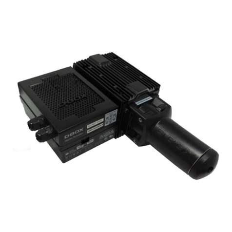
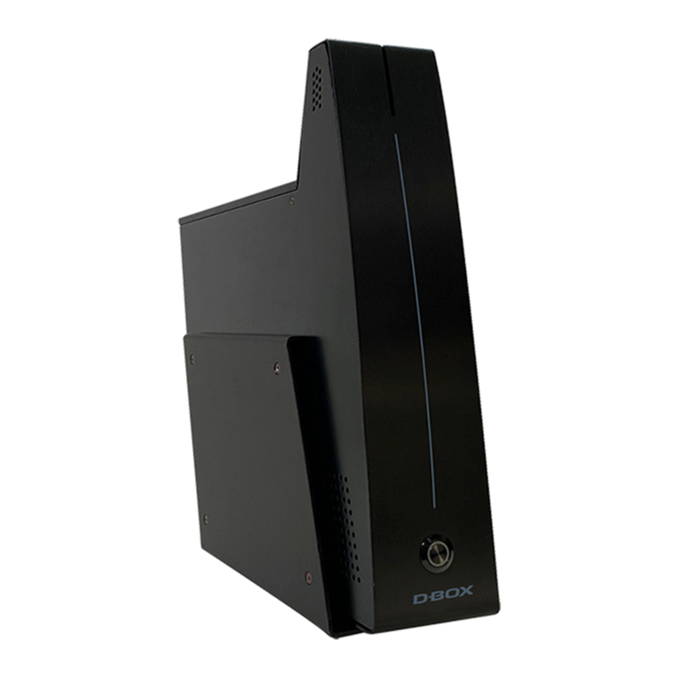
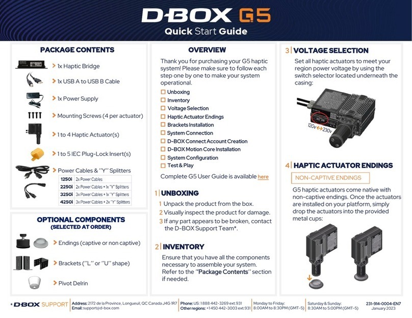
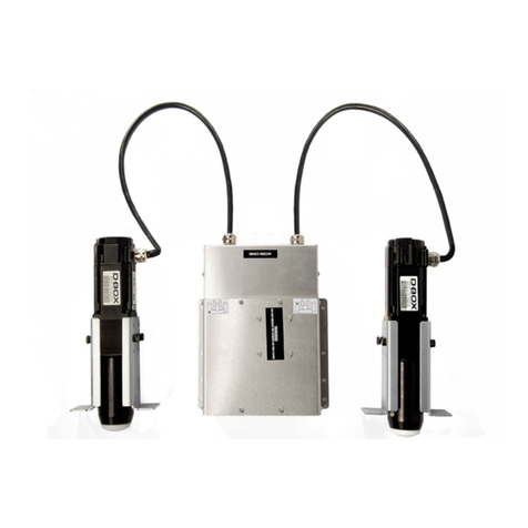
D-Box 3250i User manual

2 of 15
Table of Contents
1Components and Required Tools.................................................................................................. 5
2Actuators........................................................................................................................................ 6
2.1 Setting the ACM......................................................................................................................... 6
2.2 Front Right Actuator .................................................................................................................. 6
2.3 Front Left Actuator..................................................................................................................... 7
2.4 Rear Actuator............................................................................................................................. 7
3ACM............................................................................................................................................... 8
3.1 Placing the ACM........................................................................................................................ 8
3.2 Securing the ACM...................................................................................................................... 8
4Cables............................................................................................................................................ 9
5Tests............................................................................................................................................ 10
5.1 Routing the Cables.................................................................................................................. 10
5.2 Series IV-BD Motion Controller ............................................................................................... 10
5.3 340C Motion Controller............................................................................................................ 10
5.4 PC Motion Controller (MCI-4P or MCI-2P).............................................................................. 11
5.5 PC Motion Controller (KAI-1P) ................................................................................................ 11
6Technical Drawings ..................................................................................................................... 12
6.1 D-BOX 3250i Actuator Dimensions (.75” Bracket).................................................................. 12
6.2 Actuator Control Module (ACM) Dimensions .......................................................................... 12
6.3 Connections to the ACM Unit .................................................................................................. 13
6.4 Connections to the ACM Unit .................................................................................................. 13
6.5 D-BOX 3250i Electrical diagram.............................................................................................. 14
Appendix 1 Installation of the ACM bracket 15

3 of 15
1. Read these instructions.
IMPORTANT SAFETY INSTRUCTIONS
2. Keep these instructions.
3. Heed all warnings.
4. Follow all instructions.
5. Do not use this apparatus near water.
6. Clean only with dry cloth.
7. Do not block any ventilation openings. Install in accordance with the manufacturer's instructions.
8. Do not install near any heat sources such as radiators, heat registers, stoves, or other apparatus (including
amplifiers) that produce heat.
9. Do not defeat the safety purpose of the polarized or grounding-type plug. A polarized plug has two blades with
one wider than the other. A grounding type plug has two blades and a third grounding prong. The wide blade or
the third prong are provided for your safety. If the provided plug does not fit into your outlet, consult an electrician
for replacement of the obsolete outlet.
10. Protect the power cord from being walked on or pinched particularly at plugs, convenience receptacles, and the
point where they exit from the apparatus.
11. Only use attachments/accessories specified by the manufacturer.
12. Use only with the cart, stand, tripod, bracket, or table specified by the manufacturer, or sold with the apparatus.
When a cart is used, use caution when moving the cart/apparatus combination to avoid injury from tip-over.
13. Unplug this apparatus during lightning storms or when unused for long periods of time.
14. Refer all servicing to qualified service personnel. Servicing is required when the apparatus has been damaged in
any way, such as power-supply cord or plug is damaged, liquid has been spilled or objects have fallen into the
apparatus, the apparatus has been exposed to rain or moisture, does not operate normally, or has been dropped.
15. Do not expose this apparatus to dripping or splashing and ensure that no objects filled with liquids, such as
vases, are placed on the apparatus.
16. To completely disconnect this apparatus from the AC Mains, disconnect the power supply cord plug from the AC
receptacle.
17. The mains plug of the power supply cord shall remain readily operable.
18. Do not expose batteries to excessive heat such as sunshine, fire or the like.
The lightning flash with arrowhead symbol within an equilateral
triangle is intended to alert the user to the presence of uninsulated
"dangerous voltage" within the product's enclosure that may be of
sufficient magnitude to constitute a risk of electric shock to
persons.
The exclamation point within an equilateral triangle is intended to
alert the user to the presence of important operating and
maintenance (servicing) instructions in the literature accompanying
the product.
This symbol indicates that you must communicate with the
manufacturer for disposal of the equipment.
WARNING: To reduce the risk of fire or electric shock, do not expose this apparatus to rain or moisture.

4 of 15
WARNING! USE CAUTION WHEN HANDLING ACTUATOR CABLES AND
CONNECTIONS INSIDE THE ACM. THESE PRODUCTS OPERATE UNDER
EXTREMELY HIGH VOLTAGE. SERIOUS INJURY OR DEATH COULD
OCCUR IF HANDLED WHILE IN OPERATION.
The D-BOX 3250i Actuator System is designed to be installed into the armrest of qualified home theater
seating.
When properly installed, the system will give you a three (3) axis motion designed for home entertainment.
The seat will move you front to back (pitch), side to side (roll) and up and down (heave).
Each actuator has a piston that will go in and out of the cylinder, thus making the motion. At the end of
each piston there is a plastic pivot piece that will be in contact with the floor (or a floor protector and the
provided anti-skip cup). Under each cup there is a rubber pad protecting the floor and ensuring the
installation will remain in place when operating.

5 of 15
1 Components and Required Tools
Description
Quantité
ACM Unit (Actuator Control Module)
1
Actuator 3
Power Cable, 6 feet (000-090-0010-Z00) 1
Single Cup, Aluminum (810-0002)
3
Screw, Bolt, Hex, Cap, 1/4-20 X 3/4, Black (100-0551))
12
Washer, Lock, 1/4, Black (102-0051)
12
Included with the L/U bracket option (#801-0001)
Washer, Lock, tooth, 1/4, Zn (102-0053)
12
Screw, Bolt, Hex, Cap, 1/4-20 X 1, Black (000-100-0555-Z00) 12
Tiewrap, 7 3/8" (190-0014) 8
CAT5 cable, 10 feet (000-090-0011-Z00)
1
L bracket
4
U bracket
1
Clamp, Cable, 3/8” (094-0007)
1
Clamp, Cable, ½” black (094-0012) 8
Plate, Plastic, Adhesive, Tiewrap (190-0007) 1
ACM bracket
1
Included with the L bracket option (#801-0004)
Washer, Lock, tooth, 1/4, Zn (102-0053)
12
Screw, Bolt, Hex, Cap, 1/4-20 X 1, Black (000-100-0555-Z00)
12
Tiewrap, 7 3/8" (190-0014) 8
CAT5 cable, 10 feet (000-090-0011-Z00) 1
Support en L 6
Clamp, Cable, 3/8” (094-0007)
1
Clamp, Cable, ½” black (094-0012)
8
Plate, Plastic, Adhesive, Tiewrap (Tiewrap) (190-0007)
1
Support ACM (Actuator Control Module)
1
Included with the U bracket option (#801-0005)
Washer, Lock, tooth, 1/4, Zn (102-0053) 12
Screw, Bolt, Hex, Cap, 1/4-20 X 1, Black (000-100-0555-Z00) 12
Tiewrap, 7 3/8" (190-0014)
8
CAT5 cable, 10 feet (000-090-0011-Z00)
1
U bracket
3
Clamp, Cable, 3/8” (094-0007)
1
Clamp, Cable, ½” black (094-0012) 8
Plate, Plastic, Adhesive, Tiewrap (Tiewrap) (190-0007) 1
ACM bracket 1
Required Tools
3/8 inch drive ratchet
3/8 inch drive 7/16 inch socket
Phillips screwdriver / electric screwdriver
Wire cutters

6 of 15
2 Actuators
2.1 Setting the ACM
Set the ACM, with the actuators attached, in front of the installation you have chosen.
2.2 Front Right Actuator
Place the front right actuator (identified with a sticker on the ACM). Note that the right side of the
installation is actually on your left, as you face the installation.
Secure the brackets to the actuator with the supplied bolts and lock washers through the center hole.
Do not over tighten the bolts. Damage to the actuator could occur.

7 of 15
Slide the actuator with its brackets back into the square hole of the installation and secure it with four (4)
of the supplied bolts and lock washers, through the predrilled holes.
Do not over tighten the bolts. Damage to the tee nut could occur.
2.3 Front Left Actuator
Repeat previous steps for the left actuator. Note that the right side of the installation is actually on your
left, as you face the installation.
2.4 Rear Actuator
Using the supplied bolts and lock washers, secure the rear actuator bracket to the rear of the installation
through the predrilled holes.
Do not over tighten. Damage to the tee nut could occur.
Using the supplied bolts and lock washers, secure the rear actuator to the rear actuator bracket using the
bottom set of holes.
Do not over tighten. Damage to the actuator could occur.
Use center holes

8 of 15
3 ACM
3.1 Placing the ACM
Place the ACM into the installation where it will not interfere with the any other mechanism.
3.2 Securing the ACM
Secure the ACM to the bottom panel of the installation using the supplied bolts and lock washers into the
predrilled holes.
Do not over tighten. Damage to the tee nut could occur.

9 of 15
4 Cables
WARNING! WHEN SECURING CABLES TO THE INSTALLATION, BE
CAREFUL NOT TO DAMAGE THE ACTUATOR CABLES. ENSURE CABLES
ARE SECURED IN A WAY THAT THEY CANNOT BE PINCHED BY ANY
MOVING PARTS. THESE CABLES HAVE VERY HIGH VOLTAGE.
IMPROPER HANDLING OR INSTALLATION COULD CAUSE SERIOUS
INJURY OR DEATH.
Secure the actuator cables, using the supplied cable clips and screws.

10 of 15
5 Tests
5.1 Routing the Cables
Set the 3250i in its final position. Route the CAT5 and power cables from the back of the ACM (Actuator
Control Module) ensuring they do not interfere, go under or near any of the actuators.
Route the CAT5 cable to the motion controller.
Connect the CAT5 cable to the motion controller, and the power cable to an electrical outlet.
5.2 Series IV-BD Motion Controller
Turn on the power on the motion controller. After it has booted, push the red button twice to enter the
Demo mode.
The chair will cycle through test movements.
Please see the device user manual for further details regarding this application.
5.3 340C Motion Controller
Turn the power on the motion controller. After it has booted, the red light will switch amber. Press the
power button again and the motion controller will activate. Push the green button to access the main
menu. Use the bottom arrow to scroll down to “Demo”. Push the green button again to initiate the “Demo”
mode.
The chair will cycle through test movements.

11 of 15
5.4 PC Motion Controller (MCI-4P or MCI-2P)
Power on your PC and launch the D-BOX Motion Controller Interface. In the Main menu, switch the Mode
to “Demo.”
The chair will cycle through test movements.
5.5 PC Motion Controller (KAI-1P)
The KAI-1P device automatically controls one KineLink platform without user intervention.

12 of 15
6 Technical Drawings
6.1 D-BOX 3250i Actuator Dimensions (.75” Bracket)
6.2 Actuator Control Module (ACM) Dimensions

13 of 15
6.3 Connections to the ACM Unit
6.4 Connections to the ACM Unit

14 of 15
6.5 D-BOX 3250i Electrical diagram

15 of 15
Appendix 1
Installation of the ACM bracket
Table of contents
Other D-Box Controllers manuals
Popular Controllers manuals by other brands

Napoleon
Napoleon eFIRE operating instructions
Linde
Linde REDLINE C 300 instruction manual
Elimko
Elimko E-48 user manual
Full Gauge Controls
Full Gauge Controls PCT-410Ri plus quick start guide
Nordson
Nordson ValveMate 7197PCP-2K quick start guide
Whelen Engineering Company
Whelen Engineering Company MPC01 user guide

