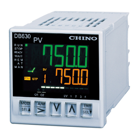
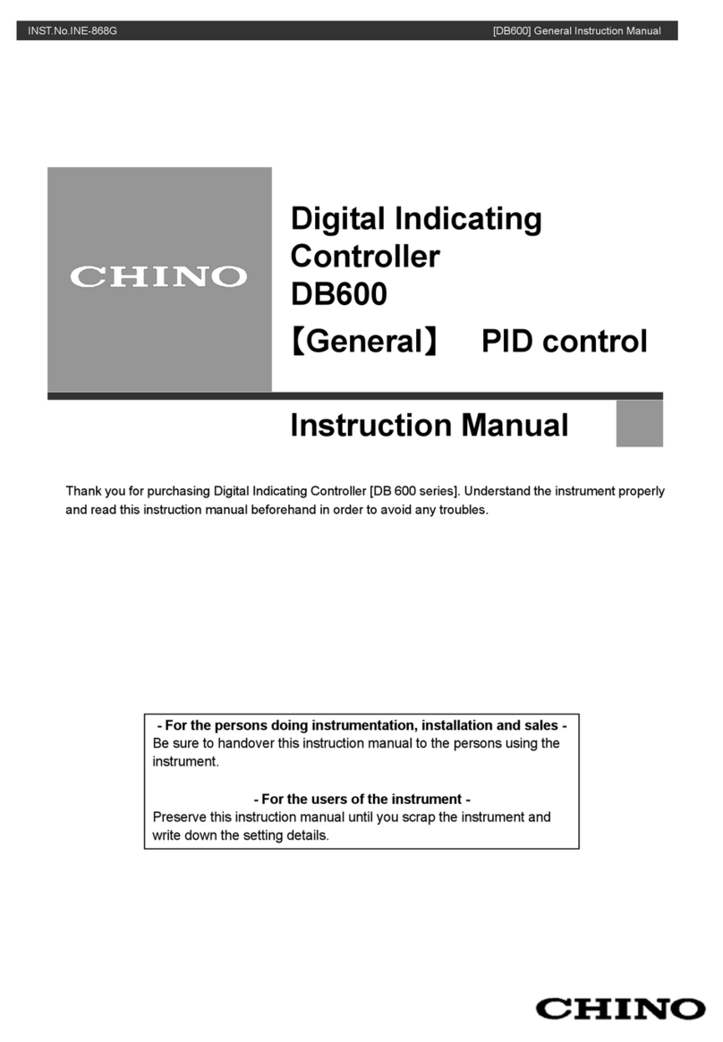
Chino KP3000 User manual

INST.No.INE-812A
Digital Program Controller
KP3000
COMMUNICATIONS
INTERFACES
Retain this manual apart from the instrument
and in an easil
y
accessible
p
lace.
Please make sure that this manual is handed to the final user of the instrument.


1. Introduction ...........................................- 1 -
2. For safe use of the product..................- 2 -
2-1 Prerequisites for use ..........................- 2 -
2-2. Symbol mark ......................................- 2 -
3. Overview ................................................- 3 -
3-1. RS-232C communication interface...- 3 -
3-2. RS-422A/485 communication interface - 3 -
4. Communication Protocol .....................- 4 -
4-1. MODBUS Protocol .............................- 4 -
4-2. PRIVATE Protocol ..............................- 4 -
5. Communication Specifications ...........- 5 -
5-1. MODBUS.............................................- 5 -
5-2. PRIVATE..............................................- 5 -
6. Setting the parameters for PC
communication .....................................- 6 -
6-1. Communication speed (COM BIT RATE)
............................................................- 7 -
6-2. Set device number (COM NUMBER) - 7 -
6-3. Set the communication function (COM
KIND) ..................................................- 7 -
6-4. Setting communication protocol (COM
PROTOCOL).......................................- 8 -
6-5. Setting communication character (COM
CHARACTER) ....................................- 8 -
7. Wiring...................................................- 10 -
7-1. Precautions while wiring.................- 10 -
7-2. Cable for communication................ - 11 -
7-3. RS-232C connection........................- 14 -
7-4. Wiring of RS-422A/485 ....................- 15 -
8. MODBUS protocol...............................- 16 -
8-1. Message transmission mode..........- 17 -
8-2. Data time interval.............................- 18 -
8-3. Message configuration....................- 18 -
8-4. Method of creating a message .......- 25 -
8-5. Function code ..................................- 26 -
8-6. Process during abnormality ...........- 30 -
8-7. Reference table ................................- 32 -
8-8. MODBUS protocol support reference
table..................................................- 53 -
9. PRIVATE protocol............................... - 59 -
9-1. Difference between RS―232C and
RS-422A/485.................................... - 59 -
9-2. Basic procedure of communication- 61 -
9-3. Communication format................... - 63 -
9-4. Positive response and negative
response.......................................... - 70 -
9-5. Communication time chart ............. - 72 -
10. Communication (Digital) transmission - 74 -
10-1. Overview ........................................ - 74 -
10-2. Specifications of communication
division............................................ - 75 -
10-3. Communication transmission
setting ............................................. - 76 -
10-4. Wiring ............................................. - 77 -
10-5. Example of combination............... - 78 -
11. Appendix ...........................................- 79 -
11-1. Communication format list ........... - 79 -
Table of Contents

-1-
1. Introduction
Thank you for purchasing Digital Program Setter 'KP3000 series'.
KP 3000 series is Digital Program Setter with output accuracy of ±0.1%, output update cycle of
approximately 0.1 seconds and front size of 96X96mm.
Up to 30 types of program patterns etc. are various functionalities that are provided as standard
provisions. Besides a digital indicator with large easy to view LED display, various settings have an
interactive system with high resolution dot matrix LCD display and handling is also easy with precise
control.
Understand the setter properly and read this instruction manual beforehand in order to avoid any
trouble.
This is a 'Communication' instruction manual. For general specifications, read 'General' instruction
manual along with this manual.
1. You should not copy or forward fully or partially this document without prior notice.
2. The contents of this document may be changed without notice.
3. We have taken enough care regarding the contents of this document however if at all you
notice a mistake or an omission contact our nearest office.
4. Please understand that regarding the result of the operation, whatever is the result the
company will not be responsible.
Notice
- For the persons doing instrumentation, installation and sales -
Be sure to handover this instruction manual to the persons using the controller.
- For the users of the controller -
Preserve this instruction manual until you scrap the controller.
Request

-2-
2. For safe use of the product
In order to use the controller safely, read the following precautions and understand them.
2-1 Prerequisites for use
The controller is a general product of component type that is to be used by mounting it in a panel for
instrumentation inside a room. Do not use it in any other condition.
When using, design a fail safe on the final product side and review regularly and use the controller after
confirming the safety of the system. For the wiring, adjustment and operation of the controller, contact a
professional having knowledge of instrumentation.
It is necessary that the people actually using this controller read this instruction manual, and have enough
understanding of various precautions and the basic operations of the controller.
2-2. Symbol mark
The following symbol marks are used in the product itself and in this instruction manual hence
understand the meaning of these symbol marks properly.
Symbol mark Meaning
If there is a possibility of death or severe injuries then explain the
precautions to avoid that possibility.
If there is a possibility of small injuries or a possibility of the controller or
its nearby devices getting damaged then explain the precautions to avoid
those possibilities.
It is a symbol for ground terminal. Always connect the ground terminal to
protective grounding.
Warning
Precaution

-3-
3. Overview
RS-232C, RS-422A, RS-485 are available in communication interface of KP and are used for
communication with personal computer (hereinafter referred to as PC).
PC can receive measurement data from KP, various parameters can be set and operation commands
can be issued. Number of KP connections is 1 for RS-232 and maximum 31 for RS-422A, RS-485.
3-1. RS-232C communication interface
RS-232C is the data communication standard set and executed by Electronic India Alliance (EIA) and
Japanese equivalent for that is JIS C 6361.
This standard is basically an interface with modem and data terminal device connected to it and only
electrical and mechanical specifications are given.
Presently RS-232C communication interface that is used in industrial instruments like PC and DB
series, only some of them completely conform to the above standards, and signal wire count and
connectors for connection etc. may sometimes differ from the standards.
As nothing is specified about the software part or what we call 'data transmission procedure' it does not
mean that the devices that RS-232C communications interface can be connected unconditionally.
Hence, it is necessary that the designer investigates and confirms the specifications and transmission
procedure of the mutual device. However if the connection partner is able to program those specifications
optionally like the PC, the designer, by creating the appropriate program, can combine it with almost all
the devices.
When investigating the RS-232C standards, the method of referring to JIS C 6361 is the simplest
method.
3-2. RS-422A/485 communication interface
RS-422A/485 communication interface can communicate by connecting in parallel the KP series of a
number of machines (maximum 31) through the signal that conforms to RS-422A/485.
PCs that have RS-422A/485 communication interface are less however as it is a serial communication,
connection can be easily done by using RS232C RS-422A/485 signal converter.
Line converter (Our company model: SC8-10) for RS-232C RS-422A/485 signal conversion is
available with our company. You may order it from us.
Difference between RS-422A and RS-485 is that RS-422A uses 4 signal wires whereas RS-485 uses 2
signal wires.

-4-
4. Communication Protocol
KP has the following two protocols and switching can be done by front key settings.
4-1. MODBUS Protocol
MODBUS is a registered trademark of SCHNEIDER company.
MODBUS protocol has two modes namely RTU mode and ASCII mode and switching can be done
using front key settings. It has the transmission function of measurement data and settings, operation
function.
4-2. PRIVATE Protocol
PRIVATE is usual CHINO protocol.
Switching is done by setting the front key. It has the transmission function of measurement data and
settings, operation function.
Old instrument of CHINO products is compatible with new instrument, however the parameter,
which can not be set by PRIVATE, can be set by MODBUS. We recommended using MODBUS
protocol if communication is set newly.

-5-
5. Communication Specifications
5-1. MODBUS
・Communication system : Half duplex asynchronous system (Polling selecting system)
・Protocol : MODBUS protocol
・Communication speed : 38400,19200,9600,4800,2400bps switching
・Start bit : 1 bit
・Data length : 7 bits (ASCII mode)
8 bits (RTU mode/ASCII mode)
・Parity bit : None/even/odd
・Step bit : 1 bit/2 bits
・Transmission code : ASCII (ASCII mode)
Binary (RTU mode)
・Error check : LRC (ASCII mode)
(Error detection) CRC-16 (RTU mode)
・Data transmission procedure : No procedure
・Usage signal name : Sending and receiving data only(Without using the control signal)
5-2. PRIVATE
・Communication system : Half duplex asynchronous system (Polling selecting system)
・Protocol : PRIVATE protocol
・Communication speed : 38400,19200,9600,4800,2400bps switching
・Start bit : 1 bit
・Data length : 7 bits
・Parity bit : Even
・Stop bit : 1 bit
・Transmission code : ASCII code
・Error check : BCC (Block check character) Check sum
(Error detection)
・Data transmission procedure : No procedure
・Usage signal name : Sending and receiving data only (Without using the control signal)

-6-
6. Setting the parameters for PC communication
According to the flow chart, set these 5 parameters 'Communication speed', 'Device number',
'Communication function', 'Communication protocol' and 'Communication character'.
1. Click
key from the operation screen.
2. Select MODE 8 from 'Select MODE screen' using
key.
3. Set the following fields of Communication settings screen (MODE 8).
Communication (Option)
↓
key
Communication speed
Select the following communication speeds using
key
Register using
key
Setting range:2400,4800,9600,19200,38400
↓
key
Device number
(For RS-422/485)
Select instrument number using
key
Register using
key
Setting range: 01 to 99
↓
key
Communication function
Select the following communication function using
key
Register using
key
Setting range: COM, TRANS
↓
key
Communication Protocol
Select the communication protocol mentioned below
using
key
Register it using
key
Setting range: MODBUS (RTU), MODBUS (ASCII),
PRIVATE
↓
key
Communication
character
Select communication characters mentioned below
using the
key and register it using
key
Setting range: 7BIT/EVEN/STOP1,7BIT/EVEN/STOP2
7BIT/ODD /STOP1,7BIT/ODD /STOP2
8BIT/NON /STOP1,8BIT/NON /STOP2
8BIT/EVEN/STOP1,8BIT/EVEN/STOP2
8BIT/ODD /STOP1,8BIT/ODD /STOP2
In case of PRIVATE, the setting is 7BIT/EVEN/STOP1.

-7-
6-1. Communication speed (COM BIT RATE)
Use KP and PC in same communication speed. (Usually initial value can be 9600 bps.)
①Display ' COMBITRATE' using
key.
②Select communication speed using
key and register it using
key.
Communication speed: 2400bps, 4800bps, 9600bps, 19200bps, 38400bps, (Initial value is
9600bps)
6-2. Set device number (COM NUMBER)
Set the device number of KP at the time of RS-422A/485.
In single to multiple KPs that communicate with the PC, always do the settings such that one KP
does not overlap with the other KPs.
①'COM NUMBER' is displayed using the
key.
②Set device number (1 to 99) using
key, select it and register it using
key.
Precautions
①Device number should be in a range from 1 to 99 and it should not
overlap with the other KPs. (Initial value 1)
②In case of RS-232C, KP is connected to 1 machine but set the
device number. Usually initial value can be 1.
6-3. Set the communication function (COM KIND)
Set the communication function.
①Display 'COM KIND' using
key.
②Select communication function using
key and register it using
key.
③If 'COM' is selected, it becomes a high order communication function.
④If 'TRANS' is selected, it becomes communication transmission function.
Communication function: COM, TRANS

-8-
6-4. Setting communication protocol (COM PROTOCOL)
①'COM PROTOCOL' is displayed using
key.
②Select communication protocol using
key and register it using
key.
Selection Communication Protocol Initial value
MODBUS (RTU) MODBUS protocol RTU mode
MODBUS (ASCII) MODBUS protocol ASCII mode
PRIVATE PRIVATE protocol
MODBUS (RTU)
ÚIf communication protocol is changed, communication character changes to initial value.
6-5. Setting communication character (COM CHARACTER)
①'COM CHARACTER' is displayed using
key.
②Select communication character using
key and register it using
key.
[MODBUS RTU]
Selection Bit length Parity Stop bit Initial value
8BIT/NON/STOP1 1
8BIT/NON/STOP2 None 2
8BIT/EVEN/STOP1 1
8BIT/EVEN/STOP2 Even 2
8BIT/ODD/STOP1 1
8BIT/ODD/STOP2
8bit
Odd 2
8BIT/NON/STOP1
[MODBUS ASCII]
Selection Bit length Parity Stop bit Initial value
7BIT/EVEN/STOP1 1
7BIT/EVEN/STOP2 Even 2
7BIT/ODD/STOP1 1
7BIT/ODD/STOP2
7bit
Odd 2
8BIT/NON/STOP1 1
8BIT/NON/STOP2 None 2
8BIT/EVEN/STOP1 1
8BIT/EVEN/STOP2 Even 2
8BIT/ODD/STOP1 1
8BIT/ODD/STOP2
8bit
Odd 2
7BIT/EVEN/STOP1

-9-
[PRIVATE] (*When communication protocol is PRIVATE, communication character screen is not
displayed)
Selection Bit length Parity Stop bit Initial value
7BIT/EVEN/STOP1 7bit Even 1 7BIT/EVEN/STOP1

- 10 -
7. Wiring
7-1. Precautions while wiring
1. Communication terminal
Depending on the communication interfaces that are specified, terminal arrangement differs.
Refer to 4-3 Wiring in instruction manual [general] for terminal numbers.
2. Total length of RS-422A/485 communication cable is less than 1.2 km
Wiring space between each device can be anything but the total cable length distance is less than
1.2km.
(Line converter Last terminal KP)
3. Take action to avoid intermixing of noise.
To avoid effect of noise place the power cable and
other communication cables away from each other
by at least 50 cm or more.
4. Always perform the crimp-style terminal
process.
One of the causes of communication defect is loss
of connection.
Always process the communication cable terminal
using 0 type or Y type crimp style terminal with
insulation sleeve.
(Terminal screw of KP, line converter is M3.5mm.)
5. Apply last terminal resistance.
When using RS-422A/485 communication, apply a resistance of 100Ωto the KP place in the last
terminal. (For details, see clause 7.4)
(General metal coating resistance is okay. It is available with our company and you may order it.)
6. Number of machines of DB connections
For RS-232C :1
For RS-422A/485 : Maximum 31
Total length of cable less than 1.2 km
Line converter KP
Otype crimp style terminal
3.7 or more
Less than 8
3.7 or moreLess than 8
Y type crimp style terminal
Insulating sleeve
Insulating sleeve
(㎜)

-11-
7-2. Cable for communication
Before connecting, prepare the exclusive communication cables. They are available with our
company also and you can order them.
7-2-1. Communication cable for RS-232C (Between PC/Line converter)
①Connection between PC (9 pin) and KP, PC (9 pin) and line converter
Cable 9 pin connector ↔0 type crimp-style terminal ↔RS-232 cable
Format
Internal wiring
Model code RZ-CRS6□□
Cable length is 1 to 15m (Specified)
② Connection between PC (25 pin) and KP, PC (25 pin) and line converter
Cable 25 pin connector ↔0 type crimp-style terminal RS-232C cable
Format
Internal wiring
Model code
RZ-CRS2□□
Cable length is 1 to 15m (Specify)
SD
RD
SG
PC side 25 pin
connector
Cable (Maximum length 15m)for RS-232C
KP
Line converter side
RD
SD
SG
Cable (Maximum length 15m)for RS-232C
PC side 9 pin
connector KP
Line converter side
SD
RD
SG
1
2
3
4
5
6
7
8
9
1
2
3
4
5
6
7
8
9
10
11
12
13
14
15
16
17
18
19
20
21
22
23
24
25 For NEC make PC 98 series

- 12 -
7-2-2. Communication cable for RS-422A
① Connection between line converter and KP
Cable 0 type crimp style terminal ↔0 type crimp style terminal RS-422A cable
(For line converter)
Format
SG (Signal grand) wiring is available on both sides using 2 wick VCTF wire that is
further twisted to 4 wicks. It is disconnected and used as there is no SG terminal on
the line converter side.
Internal
wiring
Model code
RZ-CRA2□□
Cable length is 01 to 99m (Specified)
② Connection between KPs
Cable 0 type crimp style wire ↔0 type crimp style RS-422A cable (For serial connection)
Format
SG (Signal grand) wiring is available on both sides using 2 wick VCTF wire which is
further twisted to 4 wicks.
Internal
wiring
Model code
RZ-CRA1□□
Cable length is 01 to 99m (Specified)
RD
B
RDA
SD
A
SD
B
S
G
RDB
RDA
SDA
SDB
SG
RD
B
RD
A
SD
A
SD
B
S
G
RDB
RDA
SDA
SDB
SG
KP side
SDA (Red)
SDB(Green)
SG (Blue) (Blue) SG
RDA (Black)
RDB (White)
Line converter side
(Green) RDB
(Black) SDA
(White) SDB
(Red) RDA
KP side
RDA (Red)
RDB(Green)
SG (Blue) (Blue) SG
SDA (Black)
SDB (White)
KP side
(Green) RDB
(Black) SDA
(White) SDB
(Red) RDA

- 13 -
7-2-3. Communication cable for RS-485
① Connection between line converter and KP; and between KPs
Cable 0 type crimp style terminal ↔0 type crimp style terminal RS-485 cable
Format
SG (Signal Grand) wire is available in both the terminals using 2 wick cable made by
twisting CVVS wire. It is disconnected and used as there is no SG terminal on the line
converter side.
Internal
wiring
Model code
RZ-LEC□□□
Cable length is 001 to 200m (Specified)
RDA (Black)
RDB (White)
SG (Green)
(Black) SA
(White) SB
(Green) SG
Line converter side KP side
RD
A
RD
B
S
G
SA
SB
SG

- 14 -
7-3. RS-232C connection
KP uses sending, receiving and Signal Grand (SG) only and does not use any other control signal.
In general PC as controlling is done by control signal, it does not operate just by connecting 3 signal
wires. As the wiring process in the connector, differs on how the PC controls the control signal, see the
instruction manual of the PC that is being used.
Precautions
RS-232C cable length is maximum 15m. NEC make PC98 series 9 pin
connector is 'Wiring example 1' and 25 pin connector is connected as
shown in 'Wiring example 2'.
[Wiring example 1] [Wiring example 2]
25 pin connector for PC
(PC-98 series)
K
P
25
24
14 15 16 17 18 19 20 21 22 23
1312
11
10
12345678 9
RS CS DR ER
RD
SD
SG
9 pin connector for PC
(PC-98 series/IBM-PC・AT)
6 7 8 9
1 2 3 4 5
ER CS
DR RS
K
P
RD
SD
SG

- 15 -
7-4. Wiring of RS-422A/485
Connect RS-422A/485 communication interface to the PC using line converter (Our company
model: SC8-10). Line converter and PC use only three signals namely send, receive and signal grand
and do not use any other control signal. Hence, wiring process in the connector similar to that in
RS-232C connection is necessary. (For details, see the instruction manual of the line converter.)
Wiring of RS-422A
Do not connect the SG wire to FG
terminal or grounding terminal of
the device.
Precaution
s
9 pin connector for PC
(Wiring process is required)
6 7 8 9
1 2 3 4 5
SD
RD
SG
1
2
3
4
5
6
7
8
RDA
SDB
RDB
SDA
KP
RDA
RD
B
SDA
SD
B
KP
RDA
RD
B
SDA
SD
B
KP
RDA
RD
B
SDA
SD
B
Terminal
resistance
100Ω
Line converter
Wiring of RS-485
9 pin connector for PC
(Wiring process is required)
6 7 8 9
1 2 3 4 5
SD
RD
SG
1
2
3
4
5
6
7
8
RDA
RDB
KP
SA
S
B
SG
KP
SA
S
B
SG
KP
SA
S
B
SG
Terminal
resistance
100Ω
Line converter
Do not connect the SG wire to FG
terminal or grounding terminal of the
device.
Precaution
s

- 16 -
8. MODBUS protocol
Basic procedure and precautions regarding communication
Precautions In order to avoid accidents always read the contents and understand
them.
1. When setting (Right) the parameters, setting is controlled using key operations.
Communication is possible any time in KP. Response is received against the data request
from the PC at any time.
2. Device number is necessary in RS-232C also.
In RS-232C, PC and KP are connected on one to one basis. Device is set and communication
for this device number is performed.
3. As control signal wire is not used, consider resending the command.
Serial interface of KP communicates without using the control wire. As a result, sometimes
reception defect may occur due to KP status hence consider resending the command.
4. Do not remove the communication cable or a device and do not switch ON-OFF
the power supply during communication.
If cable or device that makes up the serial interface is removed or power supply is switched
ON-OFF, operation is stopped and error may occur. If this is the status, it is necessary to reset all
the devices that make up the serial interface and redo everything from the beginning.
5. Send the next command only after confirming that the communication drive is
OFF.
In RS-422A/485, multiple devices are connected to the same communication line and only
one machine whose device number is specified by the PC drives the communication line. At that
time in order that the PC receives all the characters for sure, let some time elapse after the last
character is sent and then switch OFF the drive of communication line. If command for the next
device is sent by the PC before it gets switched OFF, signals conflict and normal communication
is not performed, hence take care when using high speed PCs. This interval is approximately
5ms.

- 17 -
8-1. Message transmission mode
There are two types of modes namely RTU (Remote Terminal Unit) mode and ASCII mode and
they are selected using the front key setting.
<Table 1 Comparison between RTU mode and ASCII mode>
Item RTU mode ASCII mode
Interface RS-232C、RS-422A、RS-485
Communication system Half duplex asynchronous system
Communication speed 2400,4800,9600,19200,38400bps
Transmission code Binary ASCII
Vertical direction ParityError check
(Error
detection)
Horizontal
direction CRC-16 LRC
Start bit 1 bit
Data length 7 bit/8 bits
Parity bit None/even/odd
Character
configuration
Stop bit 1 bit/2 bits
Message start code None : (Colon)
Message end code None CR, LF
Data time interval Less than 28 bit time Less than 1 second
8-1-1. Transmission data
RTU mode is binary forwarding. ASCII mode splits the RTU 8 bit binary into high order and low
order 4 bits and garbles each character (0 to 9, A to F).
Example) RTU mode ASCII mode
67H 36H ("6")
89H 37H ("7")
ABH 38H ("8")
39H ("9")
41H ("A")
42H ("B")
As the length of message in RTU mode is half that of ASCII mode and hence effective transmission
is done.
8-1-2. Configuration of the message frame
RTU mode is made up of message part only.
ASCII mode is made up of start character ": (Colon, 3AH)", message and end character "CR
(Carriage return, ODH) + LF (Line feed, 0AH)".
RTU mode ASCII mode
Message : Message CR LF
ASCII mode has a strong point that, as the start character is ":" it facilitates troubleshooting.
Other Chino Controllers manuals

Chino
Chino DB600 Series User manual

Chino
Chino DB630E User manual

Chino
Chino JU Series User manual

Chino
Chino JW Series User manual

Chino
Chino CP350 Series User manual

Chino
Chino DB600 Series User manual

Chino
Chino KP 2000 Series User manual

Chino
Chino LT830 Series User manual

Chino
Chino LT300 Series User manual

Chino
Chino DB600 Series User manual
Popular Controllers manuals by other brands

OGS
OGS Merlin 1000V Installation operation & maintenance

KELCO
KELCO F60 Mk2 Installation & programming manual

FASAR ELETTRONICA
FASAR ELETTRONICA FE1055 manual

ICM Controls
ICM Controls ICM326HN General Installation, Operation and Maintenance Instructions

blossom-ic
blossom-ic AVALONCOMBO+ Assembly instructions

Scott Fetzer
Scott Fetzer WESTERN CGA-200 quick start guide