YPHOS 03 User manual

03
INSTALLATION UIDE


3
Congratulations on your new lights!
Evenings at the boat are going to be so much better.
This guide will assist you to install your new YPHOS lights. The following instructions refer
to GRP (fiberglass) and wooden hulls – for other types of hulls please contact us for correct
guidance. Always make sure that you are familiar with the operations to be done and consult a
specialist to install the lights.
Always follow safety procedures and pay attention to all steps to ensure the longevity of your
new lights. Always wear protective gear and take safety first.
100 mm
3.9 in.
D17 mm
0.67 in.

4
Intended Use
Important Warnings
• Installation must be performed by a qualified installer.
• Installation must be done outside of water.
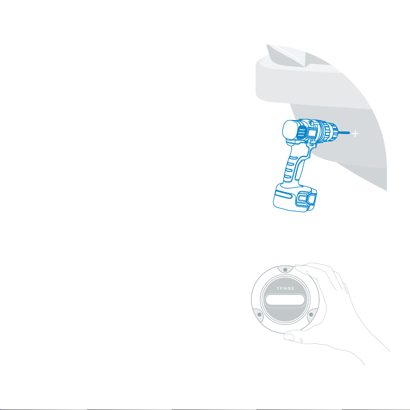
• Choose a flat area, easily accessible from the inside to mount the fixture.
• Install this fixture only on transom or sides of the hull.
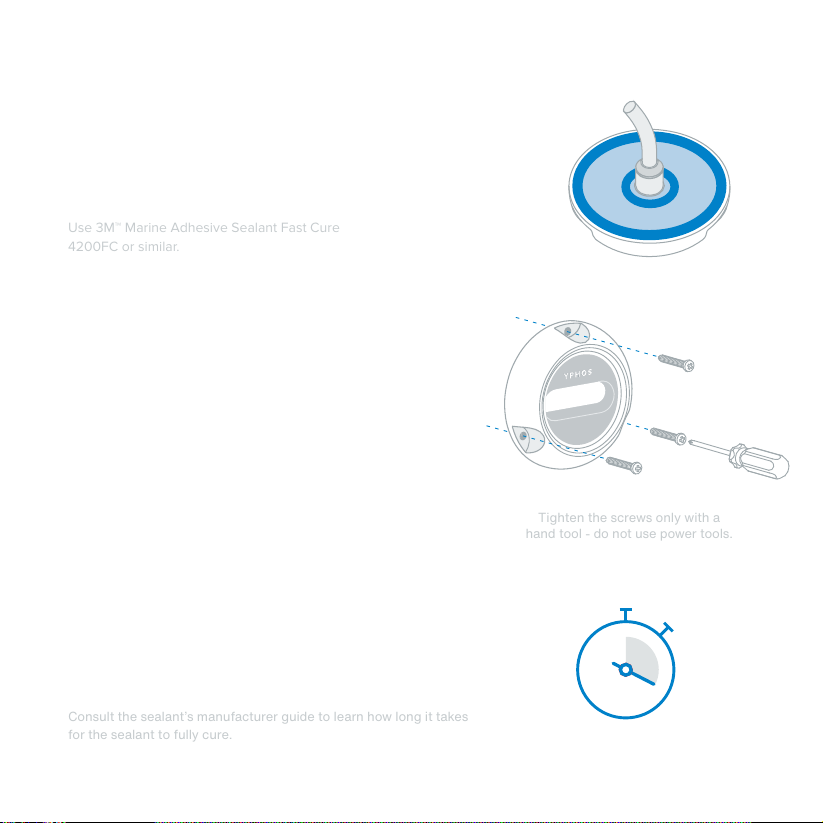
• Do not use power tools to secure the fixture.
• Do not use solvents to clean the fixture.
• Do not modify whole or any part of this product.
• Wear personal protection gear during installation.
• Complete an electrical mock-up before you modify the boat.
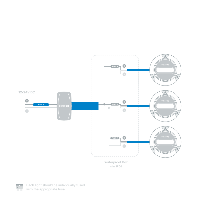
• This is a 12-24V DC light fixture. Do not connect to mains or other voltage than 12-24V DC.
• Do not look directly at the LEDs when in operation.
• Isolate power source prior to electrical installation.
• Each light should be individually fused.
• Do not allow exposed cable ends to come in contact with water. Capillary action will allow the ingress of water
through the cable, damaging the fixture or corroding the cable. This is not covered under warranty.
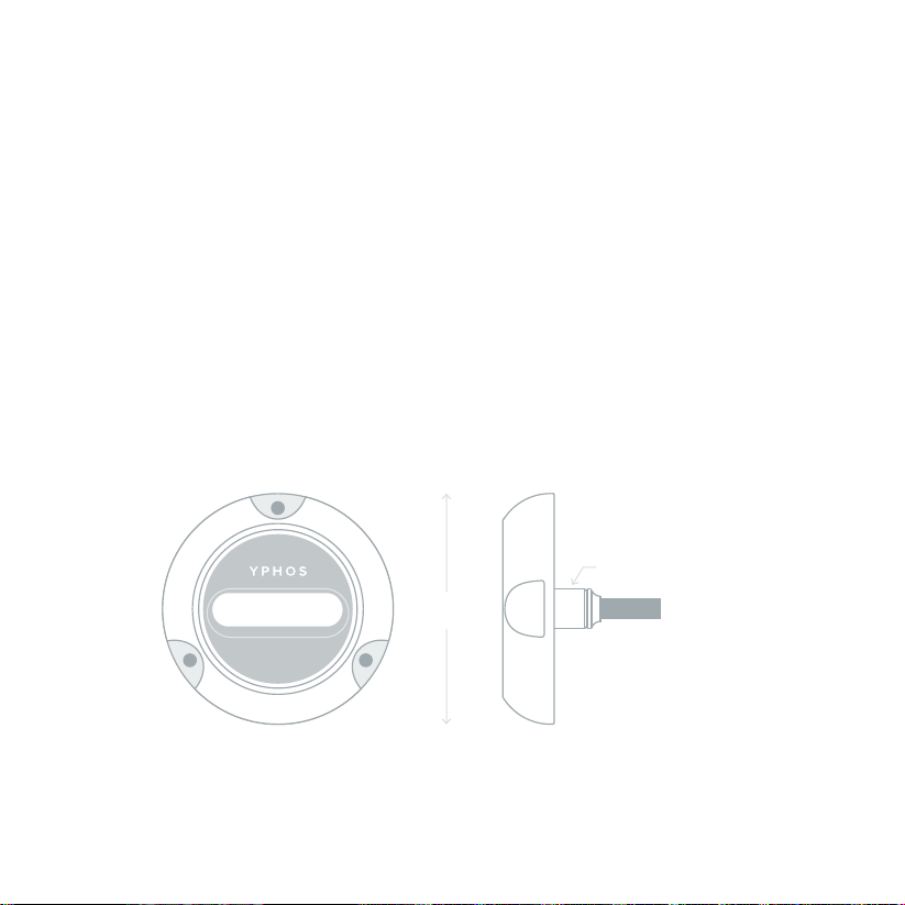
Model 03 is designed to operate as an LED Illumination unit for mounting on GRP or
wooden boat hulls. It can be installed partially or completely submerged in both fresh
and sea water and can be used anytime – while the boat is still or underway. This
installation manual does not supersede any National or Local Electrical Code.

5
In the Box
You will also need:
Make sure that all the elements shown below are in the box. If you are missing elements or
parts show signs of wear or damage, do not start the installation.
Clean ClothsSealant
3M™ Marine Adhesive
Sealant Fast Cure 4200FC
or similar
Drill Bit
Ø19mm (3/4”)
Drill Bit
Ø3mm (1/8”)
Crosshead
Screwdriver
Power Drill
2 x Fuses
3 x Tapping Screws
DIN7981 C PHIL 4.2x32 A4
Model 03 LED Fixture
with 3m (9ft) cable

6
Switch off power
This protects you and avoids damaging your equipment.
Isolate the battery or power supply to make sure that
your system is off.
Find the right spot
Select a flat surface to install the light fixture and make
sure that you have full access to the inner side of the
hull.
Make sure that no obstacles are restricting in any way
the mounting screws or the cable.
Recommended installation depth is 150-250mm
(6” - 10”) below the water line.
Inspect & Test the Light
Apply voltage to the light and confirm that it works as
intended before installation. Complete a connection
mock-up with all the necessary equipment before you
make any modification to the hull.
150 - 250mm
6” - 10”

7
Prepare the Area
Use the provided template to mark the drilling locations.
Thoroughly clean the surface and remove any debris,
coatings, fluids or solid particles to ensure proper
adhesion.
Drill
Use a Ø3mm (1/8”) drill bit for the screw pilot holes and
a Ø19mm (3/4”) drill bit for the cable hole.
Clean the surface again before you continue.
Dry Fit
After the surface is completely clean and dry on both
sides, gently guide the cable through the cable bore
and dry fit the fixture onto the hull.
Make sure that the light fixture fits properly, the holes
are aligned and that the fixture sits flat on the hull
before proceeding to the next steps.

8
Mounting
Use a crosshead screwdriver to fix the fixture onto the
hull. During this step, sealant should be evenly squeezed
around the fixture.
If there is any dry spot around the fixture, repeat the
previous step and make sure that you apply more sealant.
Use a soft cloth to remove any excess of sealant. Add
extra sealant in the inner side of the hull, around the hole.
Tighten the screws only with a
hand tool - do not use power tools.
Let the Sealant Cure
Let the sealant fully cure before you launch the boat back
into the water and do not leave your boat unattended for
the first 24 hours. Inspect for leaks during this time and act
accordingly if needed.
Consult the sealant’s manufacturer guide to learn how long it takes
for the sealant to fully cure.
Apply the Sealant
Gently pull the fixture away from the hull. Apply a
continuous bead of sealant on the back of the luminaire
and inside the drilled holes on the hull. Align the fixture
with the pilot holes and press firmly against the hull.
Use 3M™ Marine Adhesive Sealant Fast Cure
4200FC or similar.

9
Electrical Guidelines
Individually fuse each light with the appropriate type
of fuse. Consult the table on the right to select the
correct fuse rating for your lights.
Two blade-type fuses are supplied with each light.
These fuses are compatible with the YPHOS Hubs
(fused Junction Boxes) and any blade fuse holder.
Fuse recommendations
White
Blue
White + Blue
RGBW
Version 24V 12V
4 A
4 A
4 A
4 A
8 A
8 A
8 A
8 A
Do not connect the lights to any voltage other than the rated 12V-24V DC. Isolate power source
prior to installation.
Color coding of Model 03 wires is as follows:
Red: 12V or 24V DC
Black: Ground
Blue: (present in some models): Y:link
Always use appropriate type and size of cables. If you extend the factory built-in cables, always
make waterproof connections and make sure that the correct cable gauge is used following the
ABYC recommendations for DC connections.
Individually fuse each light - consult the table below.
Secure the cables and make sure that the wires are not under stress.
If lights are not synchronized, turn off for 10 seconds and on again. The Y:link enabled lights offer
absolute synchronisation between fixtures and can also be addressed.

10
RED
BLACK
Basic Wiring Diagram
applies to: 03 White
03 Blue
03 Dual Color
03 RGBW Standalone
Waterproof Box
min. IP66
12-24V DC
Each light should be individually fused
with the appropriate fuse.

11
1 Standalone mode refers to using the Model 03 RGBW without using/connecting the Y:link (blue wire).
Refer to the Y:link Hub installation manual for more information regarding Model 03 Y:link wiring.
RELAY
Wiring Diagram for YPHOS Hubs (Fused Junction Box)
applies to: 03 White
03 Blue
03 Dual Color
03 RGBW Standalone
RF Remote
up to 120m / 400ft.
Sold Separately.
12-24V DC

12
Each fused Junction Box (Basic Hub or Y:link Hub) can be used with up to 4 fixtures. You can
interconnect multiple Hubs to power and control more lights. Commands through the switch, the
RF remote or the Y:link channel are propagated from one Hub to the next.
Wiring of Multiple Yphos Fused Junction Boxes
You can also use the Model 03 RGBW with the WiFi
Brain and the smartphone app.
You can use the Model 03 RGBW with addressable
DMX/RDM functionality. Contact us for more
information.

13
All Model 03 fixtures have integrated operation modes to enhance the experience. You can cycle
through the modes by triggering the control switch OFF and ON again within 2 seconds. The
operation modes follow a cycle pattern as follows:
OFF 100% ON STROBE FADE
03 Single Color
OFF WHITE BLUE WHITE & BLUE WHITE/BLUE FADE RANDOM STROBE
03 Dual Color
ROMANCE CARIBBEAN
STROBE WHITE STROBE RANDOMCOLOR WASH 60s COLOR WASH 600s
OFF RED
CORAL
GREEN
FIRE
BLUE MAGENTAPURE WHITE MAGIC WHITE
FULL POWER
03 RGBW
When connected to an Y:link Junction Box or Controller, Model 03 RGBW lights have additional presets
and more elaborate light shows. Use the YPHOS app for even more extensive control options.
Operation Modes

14
Maintenance
YPHOS lights do not require scheduled maintenance. All parts are designed and manufactured
to last for years. However, we do recommend using a soft cloth or sponge to clean the lens from
algae or sea growth to maintain maximum light efficiency. This will be done easier if performed
while the light is still in the water. Getting the boat out of water will allow these formations to
harden and scrubbing may damage the product nano-coating and finishing.
Warranty
All YPHOS model 03 lights are covered by a warranty against defects in material and workmanship
that affect the proper operation for a period of 2 years from the date of original purchase. The
obligation of YPHOS under this Warranty is limited to the repair or replacement, at YPHOS’s
decision, of defective YPHOS products or parts. No other, consequential or not, direct or indirect
damages are covered by this Warranty and YPHOS. Damages to the product occurring from
improper use, installation, shipping, neglect or by disasters are not covered by this Warranty.
For more information visit www.yphos.com/warranty
Troubleshooting
Light does not turn on
Check that power is supplied to the light and that there is no damage to the wiring.
Check if fuse is blown or if polarity is reversed. If you are using YPHOS Hubs, check the on-board LED indications.
Light appears dim or less bright than normal
Check that the lens is clean. Confirm that voltage is 12-24V DC and stable. Make sure that the correct cable type
and gauge has been used and that cables are not damaged.
Light is flickering
Flickering can be caused if voltage is below the rated values. Make sure that flickering is not confused with the
Strobe mode.

15
Notes

Table of contents
Other YPHOS Lighting Equipment manuals
Popular Lighting Equipment manuals by other brands

Viking Stage Lighting
Viking Stage Lighting Super Vortex VK 1941 user manual

ELCART
ELCART 28/50050-00 instructions

Briteq
Briteq MICRO BEAMER RGBW Operation manual

Chauvet
Chauvet Scorpion Storm RG user manual

ProLights
ProLights PFZ725 user manual

Signtex
Signtex CAE Series Installation instructions and owner's manual

Larson Electronics
Larson Electronics HALPRM-PS-1000WMH instruction manual

Iridium
Iridium Arc Bar Pro 1215 manual

interpret
interpret ECO-MAX LED quick start guide

Govee
Govee H6179 user manual

Leuze electronic
Leuze electronic MLC 520 EX Series Original operating instructions

Seto
Seto ALDEBARAN 360 GRAD FLEX-C 2.0 Series Instructions for use