manuals.online logo
Brands
  1. Home
  2. •
  3. Brands
  4. •
  5. YSD
  6. •
  7. Controllers
  8. •
  9. YSD KZ55 User manual

YSD KZ55 User manual

KZ55 Position actuator
user's manual
一 Overview
The engine intake control valve is a combination of a
corner motor and a disk valve with a corresponding diameter,
referred to as a position control valve. This position control
valve is used together with OT3120 controller or other standard
position signals produced by the company. It can realize
open-loop and closed-loop control, and is often used for gas
engine speed control or air-fuel ratio control.
The main function of the position control valve is to
convert the position signal output by the controller into the
specified corner position. The input of the angle motor is an
electrical signal, and the output is a mechanical rotation. The
amount of mechanical rotation (rotation angle) is proportional
to the input signal.
The corner motor needs a DC drive from the controller 0V
to 20V. The drive should be able to provide a maximum
continuous current of 4A and a peak current of 10A for 30
seconds.
It is the controller, not the corner motor, that controls the
stability and dynamic response of the engine. Therefore, the
engine should be adjusted according to the instructions of the
controller.
The dimensions and installation structure dimensions of
KZ55 position control valve are as follows
Figure 1-1 KZ55 Outline drawing of position control valve
According to the diameter of the valve disc, the position
control valve of KZ series products has multiple models, KZ55
is one of them. The rotation direction of the position control
valve: facing the pointer direction, the clockwise rotation
direction is the same as the direction of increasing fuel by the
engine fuel supply system, that is: turning clockwise to increase
the amount of fuel supplied to the engine, and rotating
counterclockwise to decrease the amount of fuel supplied to the
engine.
图1-2 KZ55 Performance graph
The torque of KZ55 actuator is proportional to the current.
According to the actual use requirements and the prevention of
too much power and excessive temperature, which affects the
life of the product, the maximum continuous input current of
the controller is limited to 4A.
二 Principle description
2.1 Introduction
The speed controller sends a pulse-width-modulated PWM
signal to the angle motor by calculating the engine speed signal,
the position feedback signal and current signal of the angle
motor.
2.2 Corner motor
The rotation angle range of the rotation angle motor is 75 °
(DEG), within which the fuel supply mechanism of the engine
is controlled. The corner motor can output torque in both
directions (forward and reverse). The torque is proportional to
the current provided by the drive.
Corner motors use sealed bearings and are therefore
maintenance-free. The angular position sensor is installed at the
end of the rotor shaft and is electrically isolated from the drive
current circuit and the body.
The valve disc is mounted on the output shaft, and the
valve disc opens and closes as the angle motor moves.
2.3 Corner position sensor
The angular position sensor is mounted coaxially with the
rotor of the angular motor. The sensor is a linear, non-contact
angular position sensor. Its power supply voltage is 5VDC. The
feedback voltage is approximately: 1.6VDC at 0 ° corner,
3.3VDC at 75 ° corner (refer to 0V voltage measurement).
三 installation
Use caution when unpacking the position control valve. If
you find that the casing is deformed, scratched, or damaged,
please contact the supplier immediately.
3.1 power supply
The power output should be low-resistance (for example,
directly from the battery). The power connection wire uses
two-core insulated sheathed wires, and the ground wire uses a
single-core insulated sheathed wire. Neither the power or
ground wires need to be shielded.
If the power source is a battery, make sure the system has
an alternator or other battery charging device.
When the engine is stopped, the ESC will control the
corner motor to maintain the minimum position. At this time, if
the battery charging system is turned off, it may cause the
battery to run out of energy. To prevent this, the control system
should be closed with a switch or relay. The switch or relay
should be interlocked with the engine start switch to prevent
the engine from starting when the power to the ESC system is
cut off.
3.2 Warning-speeding
Do not use the power off method to stop the engine. Do
not turn off the power on the controller during shutdown
operation. Because closing the control valve plate will be in a
free state, all control valve position commands come from the
controller, through the drive circuit, and finally to the corner
motor. Turning off the power to the controller while the engine
is running may cause the engine to overspeed.
3.3 Position speed control valve installation
The KZ55 position speed regulating valve is suitable for
installation on the gas line of an engine or the intake pipe of an
engine below 150KW for gas or mixer air intake control. When
the position regulating valve is working normally, the current is
≤0.5A, and the heat generation is very small. Only under the
conditions of blocked rotor or other conditions that require the
maximum torque output, large heat will be generated. The main
heat of the speed control valve comes from the heat transferred
by the engine.
The installer should consider the thermal conductivity of
the mounting bracket and the engine body temperature at the
installation location. If the engine body temperature at the
installation location is too high, appropriate insulation
measures should be taken. Under normal circumstances,
aluminum and low carbon steel materials with higher thermal
conductivity should be selected as the mounting bracket, and
the installation location should be selected in a place with good
air circulation.
If there is a problem with the operating temperature,
please contact the manufacturer's engineer.
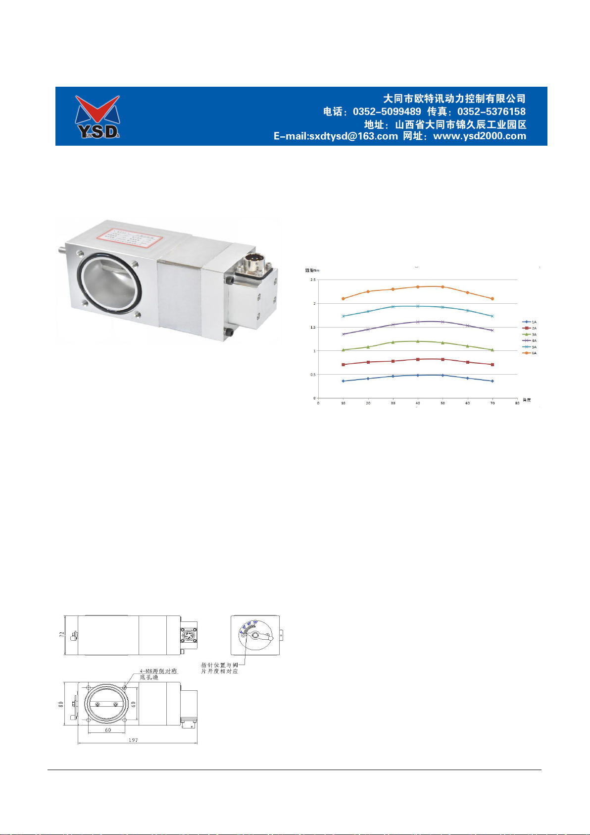
The installation method is shown in Figure 3-1. The
connection flanges are installed on both sides of the valve body,
and the contact surfaces are sealed with rubber rings. The
connection pipe can be connected to the flange.
Manual detection: The scale corresponding to the pointer
of the position control valve is the opening angle of the valve
disc. Before starting, pull the handle to confirm that the valve
disc rotates without jamming.
3-1KZ55 Connection diagram
3.4 Electrical connections
KZ55 position control valve external electrical wiring
diagram shown in Figure 3-2。
skills requirement:
1. The position control valve harness motor wire uses
more than 1.5 strands of plastic copper wire, and the sensor
wire uses 0.5 shielded wire. The length of the used wire is ≤
20m.
2. To connect the position control valve, just connect the
aviation plug of the corresponding wiring harness with the
aviation socket on the position control valve, and connect the
other end of the wiring harness to the corresponding terminal of
3120A as shown in Figure 3-4.
3-2 Electrical wiring diagram
四 Troubleshooting guide
4.1 Introduction
Governor failure is usually caused by mechanical failure
of the installation or position control valve. Before adjusting
the position control valve or controller, carefully check all
electrical connections, power supplies, and valve flexibility.
Manually move the handle on the dial side of the position
control valve manually, from 0 ° to 75 ° without jamming. If a
stagnation occurs at a certain point, it will cause the engine
speed to be unstable when it is near this air supply position.
五 Position control valve parameters
Power supply 20 VDC ~32 VDC (24 VDC nominal)
Output torque up to 5Nm
Output current 4A continuous; 10A peak, last 30 seconds
Operating temperature range -40 ℃~+100 ℃
Storage temperature range -55 ℃~+125 ℃
GJB150.16-1986 Environmental test method for military
equipment (shock test)
Vibration GJB150.16-1986 Environmental test method for
military equipment (vibration test)
Humidity at 38 ° C, 95%
Protection class

Popular Controllers manuals by other brands

ICOP Technology QEC-M-043T user manual

ICOP Technology

ICOP Technology QEC-M-043T user manual

Frymaster YUM F3000 Operation manual

Frymaster

Frymaster YUM F3000 Operation manual

Hewalex Geco G422-P01 manual

Hewalex

Hewalex Geco G422-P01 manual

cashco BQ Installation, operation & maintenance manual

cashco

cashco BQ Installation, operation & maintenance manual

Emerson 350 series instruction manual

Emerson

Emerson 350 series instruction manual

Samson 33-1 Mounting and operating instructions

Samson

Samson 33-1 Mounting and operating instructions

TREND NBOX(B)/CNC2 installation instructions

TREND

TREND NBOX(B)/CNC2 installation instructions

Delta Electronics DVP-MC Series instruction sheet

Delta Electronics

Delta Electronics DVP-MC Series instruction sheet

SAJ PDS23-2SR75 user manual

SAJ

SAJ PDS23-2SR75 user manual

Emerson Dixell XR60CHC Installing and operating instructions

Emerson

Emerson Dixell XR60CHC Installing and operating instructions

Regada SP 1 Installation, service and maintenance instructions

Regada

Regada SP 1 Installation, service and maintenance instructions

Vivo DESK-V103EW instruction manual

Vivo

Vivo DESK-V103EW instruction manual

dixell UNIVERSAL XR60CX Installing and operating instructions

dixell

dixell UNIVERSAL XR60CX Installing and operating instructions

Teleco SPC 10/1 user manual

Teleco

Teleco SPC 10/1 user manual

MOBILUS COSMO user manual

MOBILUS

MOBILUS COSMO user manual

ITOH DENKI CBM-103FN manual

ITOH DENKI

ITOH DENKI CBM-103FN manual

CBS ArcSafe RSA-34 Installation and operation

CBS ArcSafe

CBS ArcSafe RSA-34 Installation and operation

LINK-MI LM-TV15 user manual

LINK-MI

LINK-MI LM-TV15 user manual

manuals.online logo
manuals.online logoBrands
  • About & Mission
  • Contact us
  • Privacy Policy
  • Terms and Conditions

Copyright 2025 Manuals.Online. All Rights Reserved.