YTORA TPW899 User manual

....
TPW899
ThankyouforpurchasingthisYtoradevice.Pleasereadtheseoperatinginstructionscarefullyto
familiarizeyourselfwiththefeaturesandmodesofoperationbeforeusingtheinstrument.
Package Package Package PackageContents Contents Contents Contents
Unpackandremovethecontentscarefully:
•
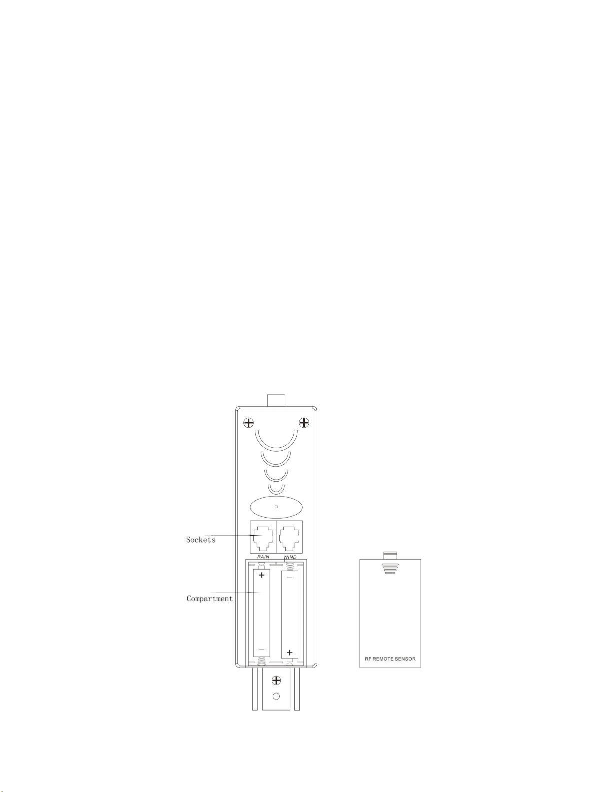
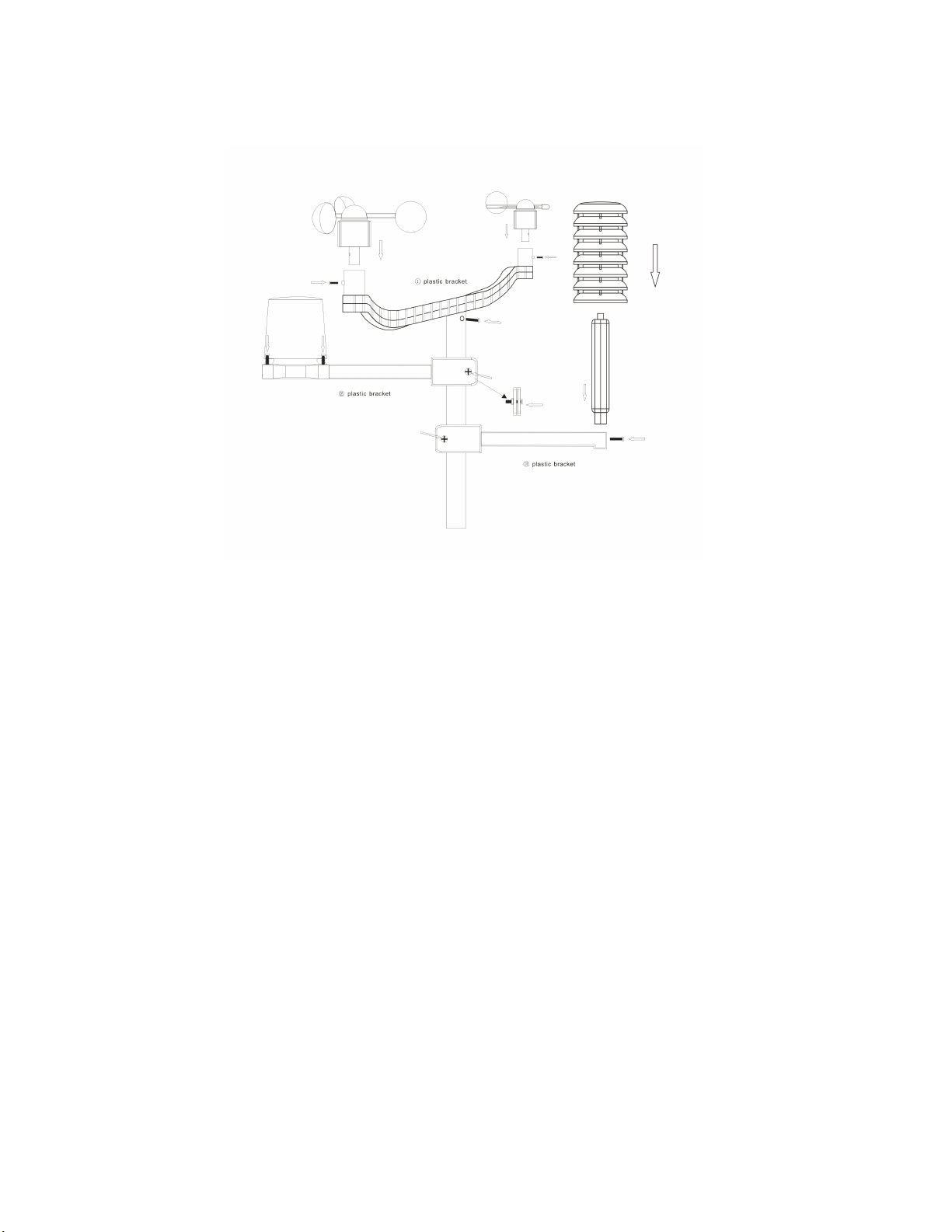
1xweatherstationmainunit
•1xstainlesssteelmast
•1xthermo-hygrosensor
•1xrainsensor
•1xwindspeedsensor
•
1xwinddirectionsensor
•Mountingscrews
•
Stainlesssteelaccessoryforfixingthemastandscrews.
Technical Technical Technical TechnicalDetails Details Details Details •
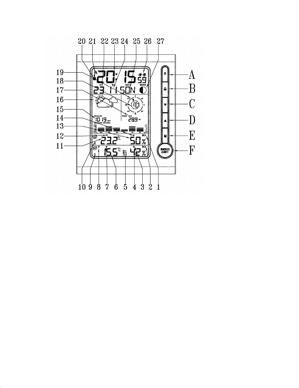
Sixkeys:A, A, A, A, ␇␇␇␇
,,,,▼,▲,M, M, M, M,SNOOZE/ SNOOZE/ SNOOZE/ SNOOZE/LIGHT. LIGHT. LIGHT. LIGHT.
•RadiocontrolledclockDCF77
•Automaticallyswitchesto/fromdaylightsavingtime(summer/wintertime)
•Timedisplayin12/24format
•24adjustabletimezones(+/-12hours)
•Continuousperpetualcalendarupto2099
•DisplayofDate,MonthandDayofweek
•Dayofweekdisplayavailablein7languages(German,English,Italian,French,Dutch
Spanish,Danish)
•Dualalarmwithsnoozefunction(5minutesalarminterruption)
•
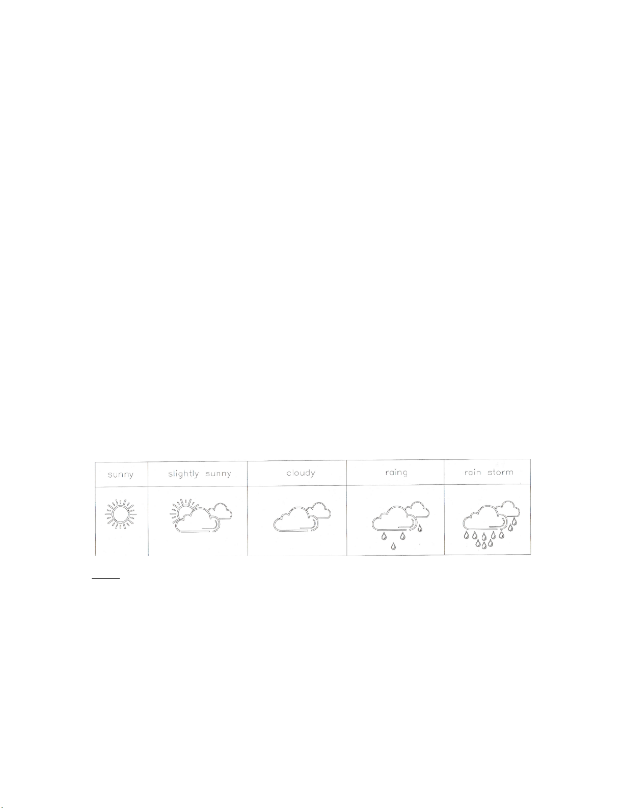
5weatherforecasticons:sunny,partlysunny,cloudy,rainy,storm.
•Barometerandbarchartfor12hoursairpressurehistory
•
Indoor/outdoortemperatureandhumiditywithtrend
•
Max./min.oftemperatureandhumidity
•Thermometermeasuringrangeinside:°Cto+50°C,outside-20°Cto60°C
•
Temperaturedisplayelectivein°Cor°F
•Temperaturealertforindoorandoutdoor
•
Livingspacehumidity
•Moonphase
•
Windspeedinkm/h(mph),windspeed0~256km/h
•Winddirectionin16directions
•Rainfallinmmandinchanddisplayof1hour,24hour,TOTAL.
Rainvolume:(0~999.9mm)
•
Lowbatteryindication
•
BlueLEDbackgroundillumination
•Mainunitbatteries:3xAA,LR6,1.5V(notincluded)

Outdoor sensor:
•F requency: 433 MHz
•Transmission range: 100 meters in open area.
Note: Actual distance may vary depending on the environment, it will be shortened in real
buildings due to electrical interference, concrete walls etc.
•Batter ies : 2 x AA, LR 6 1.5V (not included)
Installation
Installation
Installation
Installation
•
•
•
•Installing
Installing
Installing
Installing the
the
the
the Batteries
Batteries
Batteries
Batteries
•Open the main unit battery cover located at the back of the main unit and insert 3 pcs AA
batteries into the battery compartment and close the battery cover.
•Pull away the radiation shield from the thermo-hygro sensor to reveal the 2 sockets (the
sockets for the wind sensor and rain sensor)
•1. Connect the wind speed sensor cable into the socket at the bottom of the of the wind
direction sensor
2. Connect the cable from wind direction and the cable from rain sensor to the
corresponding sockets of the thermo-hygro sensor by clicking them into place.
Make sure that rain and wind cables are connected to the correct sockets.
3. Open the battery cover and insert 2 pcs AA batteries into the battery compartment and
close the battery cover.

NOTES:
NOTES:
NOTES:
NOTES:
•
First insert the batteries of main unit, then insert the batteries of the outdoor sensor within 3
minutes after the main unit is powered on, to assure that the sensor data is received well.
In case of the outdoor sensor data is not received, please press
␇
␇
␇
␇
key for more than 3
seconds to synchronize the sensors signal again.
•
Every time the batteries are replaced in the main unit, it will loose all the weather data.
•Every time the batteries are replaced in the sensor unit, it will synchronize with the main unit
only if you press the
␇
␇
␇
␇
key for more than 3 seconds.
•
•
•
•Mounting
Mounting
Mounting
Mounting the
the
the
the main
main
main
main unit
unit
unit
unitThe main unit can be placed onto any flat surface or wall mounted at the desired location by
the hanging hole at the rear side. We strongly suggest, checking that the radio signals (from
the sensors and from the DCF77 time signal) can be received before mounting.
•
•
•
•Mounting
Mounting
Mounting
Mounting the
the
the
the outdoor
outdoor
outdoor
outdoor sensor
sensor
sensor
sensor onto
onto
onto
onto the
the
the
the stainless
stainless
stainless
stainless steel
steel
steel
steel mast
mast
mast
mastFor accurate results, the outdoor sensor mast should be securely mounted onto a horizontal
surface and in an open area away from trees and other coverings where rainfall or wind
speed may be reduced causing inaccurate reading.
1. Mounting
Mounting
Mounting
Mounting the
the
the
the wind
wind
wind
wind speed
speed
speed
speed sensor
sensor
sensor
sensor to
to
to
to the
the
the
the first
first
first
first plastic
plastic
plastic
plastic bracket
bracket
bracket
bracket :first check the wind-fan
can rotate freely before fixing. The wind speed sensor should now be mounted onto the
bracket provided to allow the wind to travel around the sensor unhindered from all
directions. Please follow the below display :
2. Mounting
Mounting
Mounting
Mounting the
the
the
the wind
wind
wind
wind direction
direction
direction
direction sensor
sensor
sensor
sensor to
to
to
to the
the
the
the first
first
first
first plastic
plastic
plastic
plastic bracket
bracket
bracket
bracket : first check the wind
direction sensor before fixing. There is one cable from wind speed sensor, insert it into
the socket under the wind direction sensor. Please follow the below display:

3. Mounting
Mounting
Mounting
Mounting the
the
the
the rain
rain
rain
rain sensor
sensor
sensor
sensor to
to
to
to the
the
the
the second
second
second
second plastic
plastic
plastic
plastic bracket:
bracket:
bracket:
bracket: there are vertical engraved
lines at the bottom edge of the round cover and the sensor part, you only need adjust
the two line into one position, then turn clockwise, the rain sensor part will be connected
well, then fix them with 4 screws onto the plastic bracket ( don ’ t use only 2 screws )
please follow the below display :
4. Mount
Mount
Mount
Mount the
the
the
the thermo-hygro
thermo-hygro
thermo-hygro
thermo-hygro sensor
sensor
sensor
sensor to
to
to
to the
the
the
the third
third
third
third plastic
plastic
plastic
plastic bracket:
bracket:
bracket:
bracket: once the wind sensors
and rain sensor are fixed onto the bracket, connect the cables to the corresponding
thermo-hygro sensor sockets with the plugs, so that data can be transmitted to the main
unit, then put the aspiration cover onto the thermo-hygro sensor, please follow the below
display:
Note
Note
Note
Note : please don ’ t connect/disconnect the plugs too often nor put the plug outside in the
air for longer time in order to avoid any damage to the plugs. Otherwise the
connection can be affected negatively!

5. Mount
Mount
Mount
Mount all
all
all
all the
the
the
the sensors
sensors
sensors
sensors onto
onto
onto
onto the
the
the
the stainless
stainless
stainless
stainless steel
steel
steel
steel mast
mast
mast
mast and fix the whole sensors unit at
the pre-selected outdoor area.
(Please note: make sure that all the cables are connected well into the sockets and fix
the lose cables to the mast)

LCD
LCD
LCD
LCD overview
overview
overview
overview
1.
1.
1.
1. Indoor low battery
2.
2.
2.
2. Outdoor low battery
3.
3.
3.
3. Outdoor humidity trend
4.
4.
4.
4. Outdoor humidity
5.
5.
5.
5. Function not active
6.
6.
6.
6. Outdoor temperature
7.
7.
7.
7. Outdoor temperature trend
8.
8.
8.
8. RF sensor symbol
9.
9.
9.
9. Outdoor temperature alert
10.
10.
10.
10. Indoor temperature alert
11.
11.
11.
11. Indoor temperature
12.
12.
12.
12. Indoor temperature trend
13.
13.
13.
13. Indoor humidity
14.
14.
14.
14. Indoor humidity trend
15.
15.
15.
15. Air Pressure
16.
16.
16.
16. Weather Forecast
17.
17.
17.
17. Rainfall
18.
18.
18.
18. Wind speed
19.
19.
19.
19. Wind direction
20.
20.
20.
20. Summer time
21.
21.
21.
21. RCC symbol (DCF77 time signal)
22.
22.
22.
22. Date
23.
23.
23.
23. Time
24.
24.
24.
24. Month
25.
25.
25.
25. Day of week
26.
26.
26.
26. Dual alarm
27.
27.
27.
27. Moon Phase

Initial
Initial
Initial
Initial Operation
Operation
Operation
Operation
•After inserting the batteries, the main unit will connect with the outdoor sensor by RF signal.
The RF signal symbol at the out area will flash.
•
This process takes about 3 minutes. Then t he display shows the outdoor temperature
/humidity/wind speed/wind direction/rainfall. In case of failure of reception, press “ ␇“ for
more than 3 seconds to start a new reception.
•
The automatic receiving of the DCF77 radio controlled clock (RCC) signal begins after the
outdoor RF reception has been completed.
•While the RCC reception p rocess is going on, t he flashing symbol “ radio tower “ appears in
the time display area. In case the reception is good, the waves of the “ radio tower ” are
blinking. If the reception is not good, only the tower (without waves) will be blinking
•Once the RCC reception is successful, the symbol “ radio tower “ will be shown permanently ,
no flashing, with the waves.
If, due to bad reception or no automatic RCC time reception is possible, follow the steps below to
set the time manually .
Manual
Manual
Manual
Manual time
time
time
time set-up
set-up
set-up
set-upIn
In
In
In this
this
this
this Set-Up
Set-Up
Set-Up
Set-Up you
you
you
you make
make
make
make other
other
other
other settings
settings
settings
settings too,
too,
too,
too, such
such
such
such as
as
as
as 12/24hour,
12/24hour,
12/24hour,
12/24hour, time
time
time
time zone,
zone,
zone,
zone, languages,
languages,
languages,
languages,
display
display
display
display units
units
units
units etc.
etc.
etc.
etc.
•Press and hold key “ M “ for 3 seconds.
•The 12/24 hour flashing. Use “ ▲“ / “ ▼“ to select
•Press “ M “ to confirm.
•
The display for the time zone is flashing. Use “ ▲“ / “ ▼“ to select the time zone
(-12 to +12).
•
Press “ M “ to confirm.
•
The DM/MD flashing, Use “ ▲“ / “ ▼“ to select
•
Press “ M “ to confirm.
•The display for the year is flashing. Use “ ▲“ / “ ▼“ to select the year .
•Press “ M “ to confirm.
•The display for the month is flashing. Use “ ▲“ / “ ▼“ to select the month.
•
Press “ M “ to confirm.
•
The display for the date is flashing. Use “ ▲“ / “ ▼“ to select the date.
•Press “ M “ to confirm.
•
The display for the hour is flashing. Use “ ▲“ / “ ▼“ to select the hour.
•Press “ M “ to confirm.
•The display for the minutes is flashing. Use “ ▲“ / “ ▼“ to select the minutes..
•
Press “ M “ to confirm.
•T he language selection for the display of the weekdays is flashing. Use “ ▲“ / “ ▼“ to select
the language.
•Press “ M “ to confirm
•
The C/F for temperature flashing, Use “ ▲“ / “ ▼“ to select .
•Press “ M “ to confirm.
•The hpa/inhg for air pressure flashing, Use “ ▲“ / “ ▼“ to select .
•
Press “ M “ to confirm.
•The mm/inch for rainfall and kmh/mpg flashing, Use “ ▲“ / “ ▼“ to select .
•
Press “ M “ to confirm.

Information:
Information:
Information:
Information:
•The clock automatically changes from set-up mode to time display mode if no keys are
pressed for 20 seconds.
•
Explanation for the time zone display:
You can manually adjust the clock to the time zone of a country (within approx 1500km
distance to Frankfurt/Main in Germany) where the clock receives the DCF77 signal but where
the actual time differs from the time transmitted by the DCF77 time signal.
If, e.g. the time in a given country is 1 hour ahead of the German time, set the time zone
display to 01. The clock is now DCF77 controlled but the time displayed is one hour ahead.
Daily
Daily
Daily
Daily alarm
alarm
alarm
alarm set-up
set-up
set-up
set-up
•
Press “ M ” to switch from time display to A1 display
•
Press and hold the key “ M ” (MODE) for 3 seconds , the flashing alarm time is shown
•
The hour display of the alarm time is flashing. Use “ ▲“ / “ ▼“ to select the hour .
Press “ M ” to confirm.
•Then the minutes are flashing. Use “ ▲“ / “ ▼“ to select the minutes. Press “ M ” to confirm.
•The same setting as for A2.
Daily
Daily
Daily
Daily alarm
alarm
alarm
alarm on/off
on/off
on/off
on/off
•1st press “ ␇“ to activate the alarm 1 with alarm symbol showing.
•2
nd
press “ ␇” cancel the alarm 1, then activate the alarm 2 with alarm symbol showing
•3
rd
press “ ␇“ to activate the alarm1 and alarm 2 with both alarm symbols showing.
•4
th
press “ ␇” cancel all the alarms
Information:
Information:
Information:
Information:
•
The clock automatically changes from set-up mode to time mode if no keys are pressed for
20 seconds.
•The alarm sounds for 2 minutes if no key is pressed to stop it.
Snooze
Snooze
Snooze
Snooze function
function
function
function
To activate the snooze function, follow the steps below
•Press the key “ SNOOZE/LIGHT
SNOOZE/LIGHT
SNOOZE/LIGHT
SNOOZE/LIGHT “ , while the alarm sounds, to activate the snooze function.
•
If the snooze function is activated ,the alarm symbol is flashing.
•The alarm repeats after 5 minutes .
•The snooze function can be stopped by pressing any key.
12/24
12/24
12/24
12/24 hours
hours
hours
hours mode
mode
mode
modeThe time display can be in 12 (AM/PM )or 24 hours mode , please follow the manual set-up to
select
°
°
°
° C/
C/
C/
C/ °
°
°
° F
F
F
F temperature
temperature
temperature
temperature display
display
display
displayThe temperature display can be in ° C or ° F , please follow the manual set-up to select.

Max./
Max./
Max./
Max./ Min.
Min.
Min.
Min. memory
memory
memory
memory for
for
for
for the
the
the
the in/outdoor
in/outdoor
in/outdoor
in/outdoor temperature
temperature
temperature
temperature and
and
and
and humidity
humidity
humidity
humidityPress “▲“
“▲“
“▲“
“▲“ to display the indoor/outdoor max./min. temperature and humidity, hold “▲“
“▲“
“▲“
“▲“ for more
than 3 seconds to clear up the max./min memory
Temperature
Temperature
Temperature
Temperature alert
alert
alert
alert set-up
set-up
set-up
set-up
•Press “
“
“
“ A
A
A
A ”
”
”
”for more than 3 seconds, the upper limit of inside temperature is flashing, use
“▲“ / “ ▼“to set the maximum alert temperature.
•
Press “ A
A
A
A“ , the lower limit of inside temperature is flashing, use
“▲“ / “ ▼“
to set the minimum
alert temperature.
•Press “
“
“
“ A
A
A
A ”
”
”
”, the upper limit of outside temperature is flashing, use “▲“ / “ ▼“to set the
maximum alert temperature.
•Press “ A
A
A
A“ , the lower limit of outside temperature is flashing, use “▲“ / “ ▼“to set the
minimum alert temperature.
•
When the alert is activated, the alert symbol will be shown.
Temperature
Temperature
Temperature
Temperature alert
alert
alert
alert on/off
on/off
on/off
on/offPress the key “ A
A
A
A“ to set the temperature alert on or off.
•Alert on: Temperature alert symbol shown in display
•Alert off: Temperature alert symbol goes out.
Information
Information
Information
Information
•The set-up process cannot be completed if the maximum temperature selected is lower than
the minimum selected temperature.
•The minimum temperature selected must at least be 1 ° C below the maximum selected
temperature.
5
5
5
5 Weather
Weather
Weather
Weather forecast
forecast
forecast
forecast icons
icons
icons
icons
NOTE : The weather forecast accuracy is approximately 70%. The TPW899 shows the forecasted
(predicted), not the current conditions. The SUNNY icon indicates clear weather, even when
displayed during the night-time.
Barometer
Barometer
Barometer
Barometer and
and
and
and barchart
barchart
barchart
barchart of
of
of
of air
air
air
air pressure
pressure
pressure
pressure history
history
history
history for
for
for
for the
the
the
the past
past
past
past 12
12
12
12
hours
hours
hours
hours
The local air pressure can be indicated in hPa or inHg and a bar chart shows the pressure history
of the past 12 hours.

Wind
Wind
Wind
Wind speed
speed
speed
speed in
in
in
in mph/kmh
mph/kmh
mph/kmh
mph/kmh (
(
(
( 0~256kmh)
0~256kmh)
0~256kmh)
0~256kmh)The wind speed can be shown in mph
mph
mph
mph or kmh
kmh
kmh
kmh (km/h), please follow the manual set-up to select
mph/kmh,
mph/kmh,
mph/kmh,
mph/kmh, the display of the speed is updated in case of the sensor updated every 1 minutes.
Wind
Wind
Wind
Wind direction
direction
direction
direction
There will be 16 wind directions, the display of the direction is updated every 1 minutes
Rainfall
Rainfall
Rainfall
Rainfall display
display
display
display (0~999.99mm)
(0~999.99mm)
(0~999.99mm)
(0~999.99mm)
•Rainfall can be shown in mm
mm
mm
mm or inch
inch
inch
inch , please follow the manual set-up to select the unit.
•Press “▼“ to show the rainfall in 1 hour, press again 24 hours, then TOTAL.
•Press “▼“ for more than 3 seconds to clear up the volume accordingly, such as if
showing 1 hour, clear up the data in 1 hour, others unchanged, if showing 24 hours,
clear up the data in 24 hour, others unchanged.
•The max. of the rainfall is up to 999.99mm (99.99inch), the display is flashing in case the
limit is reached. In such a case, you have to clear the data as described above.
Otherwise, the data can not be updated any more.
Illumination
Illumination
Illumination
Illumination
Press the key “ SNOOZE/LIGHT
SNOOZE/LIGHT
SNOOZE/LIGHT
SNOOZE/LIGHT “ to activate the display illumination for 8 seconds.
Moon
Moon
Moon
Moon phase
phase
phase
phase display
display
display
displayThe weather station uses preprogrammed data to show the moon phase
A
A
A
A B
B
B
B C
C
C
C D
D
D
D E
E
E
E F
F
F
F G
G
G
G H
H
H
H
A: New moon B: Waxing crescent C: First quarter
D: Waxing gibbous E: Full moon F: Waning gibbous
G: Last quarter H: Waning crescent
Comfort
Comfort
Comfort
Comfort Zone
Zone
Zone
ZoneThe weather station uses a preprogrammed logic to determine the humidity in the living space
and shows the respective symbols.
Comfortable dry humid

Low
Low
Low
Low b
b
b
b attery
attery
attery
attery condition
condition
condition
condition display
display
display
displayThe weather station displays the low battery condition symbol to remind you to replace the
batteries in t he display unit or the outdoor sensor .
•
Display unit low battery display: within indoor area of the display
•
Outdoor sensor low battery display: in the out door area of the display
RF
RF
RF
RF connection
connection
connection
connection to
to
to
to the
the
the
the outdoor
outdoor
outdoor
outdoor sensor
sensor
sensor
sensor
•
Press and hold the key “
␇
␇
␇
␇
“ for 3 seconds to search for the outdoor sensor. The RF signal
symbol on the display in the OUT area will flash while the signal is searched. The RF
reception is more problematic in rooms with concrete walls (e.g. in the basement) and in
office buildings (interference from electronic equipment like TV, PC, Mobile Phone, Office
Lights etc). The transmission distance will be shorter in such cases, For extreme cases,
please put the main unit closer to the window and away from any potential interference.
Recep
Recep
Recep
Recep tion
tion
tion
tion of
of
of
of radio
radio
radio
radio controlled
controlled
controlled
controlled signal
signal
signal
signal
•
The DCF77 radio signal search starts automatically about 3 minutes after battery exchange.
During reception, the “ radio tower ” signal is flashing.
•Press the two keys “▼“
“▼“
“▼“
“▼“ and
and
and
and “▲“
“▲“
“▲“
“▲“ together
together
together
together (!)
(!)
(!)
(!) to enter or for more than 3 seconds to quit
the radio controlled signal reception
•The clock synchroni z es with the DCF77 radio signal automatically and daily in the early
hours at 1:00, 2:00 and 3:00 to correct potential time deviations. If the synchroni z ation is
unsuccessful ( “ radio tower “ symbol disappears), a further synchroni z ation attempt is made at
4:00 and 5:00. If it is not successful, the reception will stop during the day.
Information
Information
Information
Information
•
Flashing “ radio tower ” symbol stands for DCF77 radio signal reception started.
•
Continuous “ radio tower ” symbol stands for DCF77 radio signal reception successful.
•
Please observe a minimal distance of 2.5m to sources of interference such as televisions or
computer screens.
•
The radio signal is weaker in rooms with concrete walls (e.g. in the basement) and in office
buildings. For extreme cases, please put the main unit near a window.
•There are less atmospheric disturbances at night. A radio time signal reception is more likely
to be successful during night. One synchronization per day is sufficient to keep the time
display accuracy at 1 second.
Tip
Tip
Tip
Tip
You can adjust the time manually in case the clock cannot receive the DCF77 radio signal (due to
interferences, large distance to the sender, obstructions like mountains, etc.) As soon as the radio
signal can be received, the clock will be adjusted automatically.
® Ytora is a registered trademark of OS Technology AG/SA, Switzerland
© OS Technology AG/SA

.
.
.
.
TPW899
Nous vous remercions d'avoir choisi cette station m é t é o de Ytora . Lisez attentivement ce mode
afin de vous familiariser avec les caract é ristiques et les modes de fonctionnement avant d'utiliser
l'instrument, svp.
Contenu
Contenu
Contenu
Contenu de
de
de
de l'emballage
l'emballage
l'emballage
l'emballageD é ballez et sortez soigneusement le contenu:
•1x la station principale (le r é cepteur)
•1x m â t en acier inoxydable
•1x capteur thermo/hygro
•1x pluviom è tre
•
1x capteur de vitesse du vent
•1x capteur de direction du vent
•Vis de montage
•Accessoire en acier inoxydable pour la fixation du m â t
CARACT
CARACT
CARACT
CARACT É
É
É
É RISTIQUES
RISTIQUES
RISTIQUES
RISTIQUES
•Six boutons: A,
A,
A,
A, ␇
␇
␇
␇,
,
,
,▼ , ▲ , M,
M,
M,
M, SNOOZE/
SNOOZE/
SNOOZE/
SNOOZE/ LIGHT
LIGHT
LIGHT
LIGHT
•
R é veil radio pilot é DCF77
•R é ception du signal de l ’ heure automatique pour afficher l ’ heure exacte avec le changement
d ’ heure hiver/ é t é automatique
•Format horaire 12 ou 24 heures
•
R é glage pour 24 fuseaux horaires ( +/-12 hours)
•Calendrier continu jusqu ’ en 2099
•
Affichage de la date, du mois, du jour de la semaine
•Choix de l ’ affichage du jour de la semaine en 7 langues (allemand, anglais, italien, fran ç ais,
n é erlandais, espagnol ou danois).
•Deux alarmes avec r é p é tition de l ’ alarme toutes les 5 minutes ( "s nooze")
•Pr é visions m é t é orologiques à l ’ aide de cinq symboles : ensoleill é , l é g è rement nuageux,
nuageux, pluvieux et orageux
•La pression barom é trique affich é e dans le barographe graphique affiche les lectures de
pression d ’ air au cours des 12 derni è res heures
•
Affichage des tendances de temp é rature pour les mesures int é rieures et ext é rieures
•
Affichage minimum/maximum de l ’ humidit é relative et de la temp é rature (int é rieur et
ext é rieur)
•Thermom è tre : Plage de mesure int é rieure : 0 ° C ° ~50 ° C , ext é rieure : -20 ° C ~60 ° C
•
Affichage des temp é ratures en Celsius (C) ou en Fahrenheit (F)
•
Alarme de temp é rature pour la mesure int é rieure et ext é rieure
•
Zone confort
•
Phase de la lune
•Vitesse du vent en km/h (mph), plage de mesure 0~256km/h
•
R é solution de la direction du vent: 16 orientations
•Pr é cipitations en mm ou pouces et indication total pour 1 heure, 24 heures et accumulation
"TOTAL". Champ de mesure 0~999.9mm
•Affichage du niveau des piles
•Affichage LED bleu du r é tro é clairage
•Piles: 3 x A A / UM3 / LR 6 , 1.5V (non incluses)

Capteur sans fil:
•
Fr é quence de transmission : 433MHz
•Port é e d' é mission: jusqu' à 100m en champ libre
•Piles: 2 x AA / UM04 / LR 6 1.5V (non incluses)
Installation
Installation
Installation
Installation
•
•
•
•Installation
Installation
Installation
Installation des
des
des
des piles
piles
piles
piles
•
Ouvrez le couvercle du compartiment des piles de l ’ unit é principale situ é à l ’ arri è re de l ’ unit é
principale, ins é rez trois piles de type AA dans compartiment des piles, puis refermez le
couvercle du compartiment des piles
•
Retirez le couvercle d ’ aspiration du capteur thermo/hygro pour r é v é ler les deux (2) prises
(une pour le capteur de vent et une pour le capteur de pluie)
•1. Connectez le c â ble du capteur de vitesse du vent dans la prise situ é e dans le bas du
capteur de direction du vent
2. Branchez le c â ble du capteur de direction du vent et le c â ble du capteur de pluie dans les
prises correspondantes du capteur thermo/hygro (vous devriez entendre un clic indiquant
qu ’ ils sont bien en place).
Assurez-vous que les c â bles des capteurs de vent et de pluie sont branch é s sur les
bonnes prises.
REMARQUES:
REMARQUES:
REMARQUES:
REMARQUES:
•
Ins é rez d ’ abord les piles de l ’ unit é principale, puis celles du capteur ext é rieur dans les trois
(3) minutes suivant la mise sous tension de l ’ unit é principale, afin de garantir la bonne
r é ception des donn é es du capteur.
Si les donn é es du capteur ext é rieur ne sont pas re ç ues, appuyez sur la touche ␇
␇
␇
␇pendant
plus de trois secondes afin de resynchroniser le signal des capteurs.

•Chaque fois que vous changerez les piles de l'unit é principale, toutes les donn é es
m é t é orologiques seront perdues.
•Lors de chaque remplacement des piles de l'unit é du capteur, l'unit é principale sera
synchronis é e uniquement si vous appuyez sur la touche ␇
␇
␇
␇pendant plus de trois secondes.
•
•
•
•Montage
Montage
Montage
Montage de
de
de
de l'unit
l'unit
l'unit
l'unit é
é
é
é principale
principale
principale
principaleVous pouvez installer l'unit é principale sur toute surface plate, ou l'installer sur un mur à
l'endroit souhait é à l'aide de l'orifice de suspension situ é à l'arri è re. Nous recommandons
vivement de v é rifier la bonne r é ception des signaux radio ( é mis par les capteurs et par le
signal horaire DCF77) avant l'installation.
•
•
•
•Installation
Installation
Installation
Installation du
du
du
du capteur
capteur
capteur
capteur ext
ext
ext
ext é
é
é
é rieur
rieur
rieur
rieur sur
sur
sur
sur le
le
le
le m
m
m
m â
â
â
â t
t
t
t en
en
en
en acier
acier
acier
acier inoxydable
inoxydable
inoxydable
inoxydableAfin d'obtenir des r é sultats pr é cis, vous devez installer le m â t du capteur ext é rieur en toute
s é curit é sur une surface horizontale et dans une zone d é gag é e d'arbres et autres
obstructions pouvant r é duire le niveau des pr é cipitations ou la vitesse du vent, ce qui
entra î nerait des lectures impr é cises.
1. Montage
Montage
Montage
Montage du
du
du
du capteur
capteur
capteur
capteur de
de
de
de vitesse
vitesse
vitesse
vitesse du
du
du
du vent
vent
vent
vent sur
sur
sur
sur le
le
le
le premier
premier
premier
premier support
support
support
support en
en
en
en plastique
plastique
plastique
plastique
:
v é rifiez d'abord que l' é olienne peut tourner librement avant de la fixer. Vous devez
maintenant installer le capteur de vitesse du vent sur le support fourni afin que le vent
puisse parvenir sans encombre jusqu'au capteur depuis n'importe quelle direction.
Veuillez suivre les instructions ci-dessous :
2. Montage
Montage
Montage
Montage du
du
du
du capteur
capteur
capteur
capteur de
de
de
de direction
direction
direction
direction du
du
du
du vent
vent
vent
vent sur
sur
sur
sur le
le
le
le premier
premier
premier
premier support
support
support
support en
en
en
en plastique
plastique
plastique
plastique :
v é rifiez d'abord le capteur de direction du vent avant de le fixer. Il y a un c â ble partant du
capteur de vitesse du vent, ins é rez-le dans la prise situ é e sous le capteur de direction
du vent. Veuillez suivre les instructions ci-dessous :

3. Montage
Montage
Montage
Montage du
du
du
du capteur
capteur
capteur
capteur de
de
de
de pluie
pluie
pluie
pluie sur
sur
sur
sur le
le
le
le second
second
second
second support
support
support
support en
en
en
en plastique
plastique
plastique
plastique :
:
:
:il y a deux lignes
verticales grav é es sur le bord inf é rieur du couvercle rond et sur le capteur, vous devrez
ajuster les deux lignes sur une position, puis faire pivoter dans le sens des aiguilles
d'une montre, le capteur de pluie sera connect é correctement, fixez-les ensuite avec les
quatre vis sur le support en plastique (n'utilisez pas que deux vis). Veuillez suivre les
instructions ci-dessous :
4. Montage
Montage
Montage
Montage du
du
du
du capteur
capteur
capteur
capteur thermo/hygrom
thermo/hygrom
thermo/hygrom
thermo/hygrom è
è
è
è tre
tre
tre
tre sur
sur
sur
sur le
le
le
le troisi
troisi
troisi
troisi è
è
è
è me
me
me
me support
support
support
support en
en
en
en plastique
plastique
plastique
plastique :
:
:
:
apr è s avoir fix é les capteurs de vent et de pluie sur le support, branchez les c â bles sur
les prises correspondantes du capteur thermo/hygro, afin que les donn é es puissent ê tre
transmises à l'unit é principale, puis d é posez le couvercle d'aspiration sur le capteur
thermo/hygro, veuillez suivre les instructions ci-dessous :
Remarque
Remarque
Remarque
Remarque : ne branchez/d é branchez pas les prises trop souvent, et ne les exposez pas
à l'air pour une p é riode prolong é e afin d' é viter de les endommager Autrement, cela
pourrait nuire à la connexion !

5. Montez
Montez
Montez
Montez tous
tous
tous
tous les
les
les
les capteurs
capteurs
capteurs
capteurs sur
sur
sur
sur le
le
le
le m
m
m
m â
â
â
â t
t
t
t en
en
en
en acier
acier
acier
acier inoxydable
inoxydable
inoxydable
inoxydable , puis fixez toute l'unit é des
capteurs à l'endroit ext é rieur pr é alablement choisi.
(Veuillez remarquer : assurez-vous que tous les c â bles sont correctement connect é s aux
prises, puis fixez les c â bles au m â t)

Affichage
Affichage
Affichage
Affichage LCD
LCD
LCD
LCD
1.
1.
1.
1. Piles faibles dans la station
2.
2.
2.
2. Piles faibles dans le capteur ext é rieur
3.
3.
3.
3. Tendance hygrom è tre ext é rieure
4.
4.
4.
4. Hygrom è tre ext é rieure
5.
5.
5.
5. Fonction pas active
6.
6.
6.
6. Temp é rature ext é rieure
7.
7.
7.
7. Tendance temp é rature ext é rieure
8.
8.
8.
8. Symbole du capteur ext é rieur
9.
9.
9.
9. Alarme temp é rature ext é rieure
10.
10.
10.
10. Alarme temp é rature int é rieure
11.
11.
11.
11. Temp é rature int é rieure
12.
12.
12.
12. Tendance temp é rature int é rieure
13.
13.
13.
13. Hygrom è tre int é rieure
14.
14.
14.
14. Tendance hygrom è tre int é rieure
15.
15.
15.
15. Pression atmosph é rique
16.
16.
16.
16. Pr é vision m é t é o
17.
17.
17.
17. Pluie
18.
18.
18.
18. Vitesse du vent
19.
19.
19.
19. Direction du vent
20.
20.
20.
20. Summer time
21.
21.
21.
21. Symbole de l ’ heure radio-pilot é e (signale DCF77)
22.
22.
22.
22. Date
23.
23.
23.
23. Heure
24.
24.
24.
24. Mois
25.
25.
25.
25. Jour de la semaine
26.
26.
26.
26. Symboles des 2 r é veils
27.
27.
27.
27. Phase de la lune

Mise
Mise
Mise
Mise en
en
en
en service
service
service
service
•Apr è s avoir ins é r é les piles, l'unit é principale se connectera au capteur ext é rieur via un
signal RF.
Le symbole du signal RF de la zone ext é rieure clignotera.
•
Ce processus dure trois minutes environ. L' é cran affichera ensuite la temp é rature/humidit é
ext é rieures, la vitesse du vent, la direction du vent, et les pr é cipitations. En cas d'interruption
de la r é ception, appuyez sur la touche « ␇» pendant plus de trois secondes pour d é marrer
une nouvelle r é ception.
•
La r é ception automatique du signal de l'horloge DCF77 radio pilot é e (RCC) commence
apr è s l'obtention de la r é ception RF ext é rieure.
•Pendant le processus de r é ception RCC, le symbole clignotant « tour radio » appara î t dans
la zone d'affichage de l'heure. Si la r é ception est bonne, les ondes de la « tour radio »
clignoteront. Si la r é ception est mauvaise, seule la tour (sans les ondes) clignotera.
•Apr è s l' é tablissement de la r é ception RCC, le symbole « tour radio » , ainsi que les ondes,
s'afficheront en permanence, sans clignoter.
En cas de mauvaise r é ception ou d'impossibilit é de recevoir l'heure RCC, suivez les é tapes ci-
dessous pour r é gler l'heure manuellement.
R
R
R
R é
é
é
é glage
glage
glage
glage manuel
manuel
manuel
manuel de
de
de
de l'heure
l'heure
l'heure
l'heureDans ce r é glage vous trouvez aussi d'autres param è tres tels que les r é glages pour 12/24heure,
fuseau horaire, les langues, les unit é s d'affichage etc.
•
Pressez et maintenez le bouton "M" pendant trois secondes.
•L ’ affichage 24h commence à clignoter. Utilisez maintenant “ ▲ “ / “ ▼ “ pour r é gler le format
horaire 12h ou 24h. Dans le mode 12h, le symbole AM (matin) ou PM (apr è s-midi) sera
affich é .
•Pressez le bouton "M" pour confirmer votre r é glage.
•L ’ affichage du fuseau horaire commence à clignoter , utilisez maintenant “ ▲ “ / “ ▼ “ pour
r é gler correctement le fuseau horaire (-12 to +12).
•Pressez le bouton "M" pour confirmer votre r é glage.
•
L'affichage DM/MD commence a clignoter, utilisez maintenant “ ▲ “ / “ ▼ “ pour r é gler le
format du jour (D) / mois (M)
•
Pressez le bouton "M" pour confirmer votre r é glage.
•
L ’ affichage de l ’ ann é e commence à clignoter. Utilisez maintenant “ ▲ “ / “ ▼ “ pour r é gler
•
Pressez le bouton "M" pour confirmer votre r é glage.
•L ’ affichage du mois commence à clignoter. Utilisez maintenant “ ▲ “ / “ ▼ “ pour r é gler
•
Pressez le bouton "M" pour confirmer votre r é glage.
•L ’ affichage de la date commence à clignoter. Utilisez maintenant “ ▲ “ / “ ▼ “ pour r é gler
•
Pressez le bouton "M" pour confirmer votre r é glage.
•
L ’ affichage des heures commence à clignoter. Utilisez maintenant “ ▲ “ / “ ▼ “ pour r é gler
•
Pressez le bouton "M" pour confirmer votre r é glage.
•
L ’ affichage des minutes commence à clignoter. Utilisez maintenant “ ▲ “ / “ ▼ “ pour r é gler
•Pressez le bouton "M" pour confirmer votre r é glage.
•
La langue du jour de la semaine commence à clignoter. Utilisez maintenant “ ▲ “ / “ ▼ “ pour
r é gler la langue de votre choix. Il existe sept langues disponibles pour l ’ affichage du jour de
la semaine : allemand, anglais, italien, fran ç ais, n é erlandais, espagnol ou danois.
•
Pressez le bouton "M" pour confirmer votre r é glage.
•L'unit é de la temp é rature commence a clignoter ( ° C ou ° F). Utilisez maintenant “ ▲ “ /
“ ▼ “ pour r é gler.
•Pressez le bouton "M" pour confirmer votre r é glage.

•
L'unit é de la pression atmosph é rique commence à clignoter (hPa ou inhg). Utilisez
maintenant “ ▲ “ / “ ▼ “ pour r é gler.
•
Pressez le bouton "M" pour confirmer votre r é glage.
•L'unit é du pluviom è tre commence à clignoter (mm ou inch). Utilisez maintenant “ ▲ “ /
“ ▼ “ pour r é gler.
•
Pressez le bouton "M" pour confirmer votre r é glage.
Information:
Information:
Information:
Information:
•Apr è s env. 20 secondes sans presser un bouton, le r é veil passe automatiquement du mode
de r é glage au mode normal
•
Fuseau horaire
Si vous r é glez un fuseau horaire, l ’ heure corrig é e s ’ affiche dans l ’ affichage de l ’ heure. Ceci
est id é al pour les lieux qui re ç oivent le signal horaire DCF77, mais qui ont n é anmoins une
heure divergente comme par ex. la Grande-Bretagne (-1HR) ou la Finlande (+1HR)
R
R
R
R é
é
é
é glage
glage
glage
glage des
des
des
des alarmes
alarmes
alarmes
alarmes du
du
du
du r
r
r
r é
é
é
é veil
veil
veil
veil
•Pressez le bouton "M" pour s é lectionner le mode A1 (alarme 1).
•
Maintenez le bouton "M" enfonc é pendant trois secondes jusqu ’à ce que l ’ heure A1 clignote
•Utilisez maintenant “ ▲ “ / “ ▼ “ pour r é gler correctement l ’ heure de l ’ alarme
•
Pressez le bouton "M" pour r é gler les minutes A1.
•Utilisez maintenant les boutons “ ▲ “ / “ ▼ “ pour r é gler les minutes de l ’ alarme
•
Pressez le bouton « MODE » pour confirmer
•Pour r é gler l ’ alarme 2 (A2), proc é dez comme d é crit ci-dessus.
Activer/supprimer
Activer/supprimer
Activer/supprimer
Activer/supprimer le
le
le
le r
r
r
r é
é
é
é veil
veil
veil
veil
•1
è re
pression du bouton “ ␇“ pour activer alarme 1: le symbole d'alarme 1 appara î tra
•
2
è me
pression du bouton “ ␇“ pour supprimer alarme 1 et activer alarme 2: le symbole
d'alarme 2 appara î tra
•3
è me
pression du bouton “ ␇“ pour activer alarme1 et 2: les 2 symboles d'alarme appara î trent.
•4
è me
pression du bouton “ ␇” pour supprimer les 2 alarmes
Information:
Information:
Information:
Information:
•Apr è s env. 20 secondes sans presser un bouton, le r é veil passe automatiquement du mode
de r é glage au mode normal
•
L ’ alarme sonnera pendant deux minutes si vous ne la d é sactivez pas en pressant n ’ importe
quel bouton
Fonction
Fonction
Fonction
Fonction de
de
de
de r
r
r
r é
é
é
é petition
petition
petition
petition d'alarme
d'alarme
d'alarme
d'alarme "Snooze"
"Snooze"
"Snooze"
"Snooze"•Pour activer la fonction de rappel d ’ alarme automatique : Tandis que l ’ alarme sonne, pressez le bouton
« SNOOZE/LIGHT » pour activer la fonction de rappel d ’ alarme. Lorsque la fonction de rappel est
activ é e, le symbole d ’ alarme clignotera.
•Le cycle de rappel d ’ alarme dure cinq minutes.

M
M
M
M é
é
é
é moire
moire
moire
moire temp
temp
temp
temp é
é
é
é rature/humidit
rature/humidit
rature/humidit
rature/humidit é
é
é
é relative
relative
relative
relative maximale/minimale
maximale/minimale
maximale/minimale
maximale/minimalePressez bri è vement le bouton “▲“ pour afficher la temp é rature et l ’ humidit é relative
maximale/minimale. Apr è s cinq secondes, l ’é cran retourne à l ’ affichage normal.
Pressez et maintenez le bouton “▲“ pendant 3 secondes pour supprimer les enregistrements
maximum et minimum.
R
R
R
R é
é
é
é glage
glage
glage
glage de
de
de
de l'alarme
l'alarme
l'alarme
l'alarme de
de
de
de temp
temp
temp
temp é
é
é
é rature
rature
rature
rature
•
Pressez et maintenez le bouton "A" enfonc é pendant trois secondes, jusqu ’à ce que, dans
l ’ affichage de temp é rature int é rieur, la limite maximale d'alerte de la temp é rature int é rieure
(50.0 ° C) s ’ affiche et clignote.
•Pressez “ ▲ “ / “ ▼ “ pour r é gler la temp é rature maximale d'alerte.
•Pressez le bouton "A", la limite minimale d'alerte (-8.0 ° C) s ’ affiche et clignote.
•Pressez “ ▲ “ / “ ▼ “ pour r é gler la temp é rature minimale d'alerte.
•Pressez le bouton "A", dans l ’ affichage de la temp é rature ext é rieure, la limite maximale
d'alerte de la temp é rature ext é rieure (70 ° C) s ’ affiche et clignote.
•
Pressez “ ▲ “ / “ ▼ “ pour r é gler la temp é rature maximale d'alerte.
•Pressez le bouton "A", la limite minimale d'alerte de la temp é rature ext é rieure (-49 ° C)
s ’ affiche et clignote.
•Pressez “ ▲ “ / “ ▼ “ pour r é gler la temp é rature minimale d'alerte.
Alerte
Alerte
Alerte
Alerte de
de
de
de la
la
la
la temp
temp
temp
temp é
é
é
é rature
rature
rature
rature activ
activ
activ
activ é
é
é
é e/d
e/d
e/d
e/d é
é
é
é sactiv
sactiv
sactiv
sactiv é
é
é
é e
e
e
eAppuyez sur la touche « A
A
A
A» pour activer ou d é sactiver l'alerte de la temp é rature.
•Alerte activ é e : le symbole d'alerte de la temp é rature s'affiche à l' é cran
•
Alerte d é sactiv é e : le symbole d'alerte de la temp é rature n'est pas affich é .
Informations
Informations
Informations
Informations
•
Vous ne pourrez pas achever le processus d'installation si la temp é rature maximale
s é lectionn é e est inf é rieure à la temp é rature minimale s é lectionn é e.
•La temp é rature minimale s é lectionn é e doit ê tre inf é rieure à la temp é rature maximale
s é lectionn é e d'au moins 1 ° C.
Other manuals for TPW899
1
Table of contents
Languages:
Other YTORA Weather Station manuals
Popular Weather Station manuals by other brands

Oregon
Oregon BA2000 user manual

PCE Health and Fitness
PCE Health and Fitness WH-1080PC Operation manual

BALANCE TIME
BALANCE TIME 862458 user manual

Celestron
Celestron 47007 Using instructions

La Crosse Technology
La Crosse Technology WS-2510 Commissioning instructions

Pisla
Pisla 70100030 instruction manual